EP0067486B1 - Carrier transporting apparatus - Google Patents
Carrier transporting apparatus Download PDFInfo
- Publication number
- EP0067486B1 EP0067486B1 EP82200711A EP82200711A EP0067486B1 EP 0067486 B1 EP0067486 B1 EP 0067486B1 EP 82200711 A EP82200711 A EP 82200711A EP 82200711 A EP82200711 A EP 82200711A EP 0067486 B1 EP0067486 B1 EP 0067486B1
- Authority
- EP
- European Patent Office
- Prior art keywords
- carrier
- trough
- lip
- axis
- disposed
- Prior art date
- Legal status (The legal status is an assumption and is not a legal conclusion. Google has not performed a legal analysis and makes no representation as to the accuracy of the status listed.)
- Expired
Links
- 239000000126 substance Substances 0.000 claims description 20
- 238000001035 drying Methods 0.000 claims description 8
- 239000000463 material Substances 0.000 claims description 3
- 238000000151 deposition Methods 0.000 claims 2
- 230000003213 activating effect Effects 0.000 claims 1
- 230000013011 mating Effects 0.000 claims 1
- 230000007723 transport mechanism Effects 0.000 description 14
- 230000007246 mechanism Effects 0.000 description 8
- 230000032258 transport Effects 0.000 description 6
- 239000003570 air Substances 0.000 description 5
- 230000000717 retained effect Effects 0.000 description 4
- 238000012545 processing Methods 0.000 description 3
- 238000004140 cleaning Methods 0.000 description 2
- 238000005096 rolling process Methods 0.000 description 2
- 238000013019 agitation Methods 0.000 description 1
- 239000012080 ambient air Substances 0.000 description 1
- 230000000712 assembly Effects 0.000 description 1
- 238000000429 assembly Methods 0.000 description 1
- 239000000969 carrier Substances 0.000 description 1
- 238000012993 chemical processing Methods 0.000 description 1
- 230000006835 compression Effects 0.000 description 1
- 238000007906 compression Methods 0.000 description 1
- 210000004247 hand Anatomy 0.000 description 1
- 238000003780 insertion Methods 0.000 description 1
- 230000037431 insertion Effects 0.000 description 1
- 239000004033 plastic Substances 0.000 description 1
- 230000001681 protective effect Effects 0.000 description 1
- 230000035945 sensitivity Effects 0.000 description 1
- 230000003595 spectral effect Effects 0.000 description 1
- XLYOFNOQVPJJNP-UHFFFAOYSA-N water Substances O XLYOFNOQVPJJNP-UHFFFAOYSA-N 0.000 description 1
- 210000000707 wrist Anatomy 0.000 description 1
Images


Classifications
-
- G—PHYSICS
- G03—PHOTOGRAPHY; CINEMATOGRAPHY; ANALOGOUS TECHNIQUES USING WAVES OTHER THAN OPTICAL WAVES; ELECTROGRAPHY; HOLOGRAPHY
- G03D—APPARATUS FOR PROCESSING EXPOSED PHOTOGRAPHIC MATERIALS; ACCESSORIES THEREFOR
- G03D3/00—Liquid processing apparatus involving immersion; Washing apparatus involving immersion
- G03D3/08—Liquid processing apparatus involving immersion; Washing apparatus involving immersion having progressive mechanical movement of exposed material
Definitions
- the application relates to an apparatus for driving a cylindrical carrier for photographic film through a substantially semicylindrical, open-topped trough.
- the apparatus is particularly suitable for developing film sheets such as for example intraoral dental X-ray film.
- Apparatus which develops photographic film by transporting exposed film through successive tanks of chemical solutions is well known in the prior art.
- the transport mechanism usually comprises a series of rollers which direct a continuous strip of film in and out of the various tanks.
- prior art transport mechanisms usually propel the film through pairs of resilient pinch rollers disposed in the chemical tanks and along the transport path. Pinch roller assemblies are inherently difficult to clean and it was often necessary to disassemble the associated drive mechanism to allow effective removal of chemical residue.
- the present invention is particularly suited for developing X-ray film in a clinical environment.
- an apparatus according to the invention is characterized in that the apparatus is provided with
- a plurality of sheets of photographic film are retained in an open-sided, cylindrical film carrier.
- the film carrier supports the film sheets in substantially parallel, spaced apart planes which are perpendicular to the cylinder axis.
- a loading fixture facilitates placement of the film within the carrier.
- the processor mechanism successively transports the film carrier through parallel open-topped troughs filled with developer, fixer solution and water and finally deposits the carrier into a stream of heated air in a drying chamber.
- Each of the chemical troughs includes a transport mechanism which engages the film carrier near the bottom of the trough and ejects the carrier from the trough by rolling it up the inner surface of the trough wall and over a lip of the trough. The carrier then drops into a succeeding trough or into the drying chamber. The rolling movement of the carrier rotates each film sheet, in the plane of the sheet, as it is transported through the chemical solution and thus provides agitation which assures uniform development.
- a heater is provided to maintain the developer and fixer solutions at desired temperatures.
- sprocket teeth are provided on the periphery of the film carrier.
- the carrier is rotated by a moving rubber belt having outwardly directed teeth which engage the periphery of the carrier.
- a swing arm assembly holds the carrier between the belt and the inner surface of the trough wall and acts to eject the carrier over the lip of the trough.
- racks on the inner surface of the trough wall engage teeth on the periphery of the film carrier and constrain the carrier to roll along the trough surface, without slipping, as it is raised by the transport mechanism.
- a plurality of parallel racks may be utilized to assure that the carrier remains parallel to the trough and does not become cocked as it climbs the trough wall.
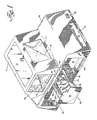
- FIGS 1 and 2 are a film processor in accordance with the present invention.
- a film transport and chemical processing mechanism is mounted on a base 59 and contained within a light-tight lower housing 10.
- An upper housing 11 is mounted on top of the lower housing and provides a safe-lighted area for loading exposed film into carriers.
- the upper housing is provided with a removable door 13 which provides access for inserting exposed film packages into the upper housing.
- the door 13 may be constructed as a transparent, safe-light window (which only passes light outside of the spectral sensitivity range of the film to be processed). When processing dental X-ray film the door 13 typically comprises a transparent amber plastic.
- a pair of openings in the sides of the upper housing are covered with rubber panels 14 and 15. The panels are provided with slits 16.
- a technician using the processor inserts his hands through the slits 16 to unwrap a light protective covering from the film sheets while viewing the operation through the window 13.
- the rubber panels close around technicians' wrist to provide a light-tight confinement for unwrapping and loading the film.
- the lower housing 10 is provided with a removable panel (not shown) which covers an opening 12.
- the opening allows access to the film transport and processing mechanism enclosed therein.
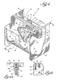
- the processing mechanism comprises three parallel open-topped chemical troughs 17, 18 and 19 each of which supports a film carrier transport mechanism 27.
- the chemical troughs are disposed side-by-side and are slidable on the base 59 for removal through the opening 12.
- a film carrier 23 (more particularly described below) is dropped from the upper housing into the input (left) side of the first trough 17 which contains a developer solution.
- the carrier transport mechanism 27 in the first trough lifts the film carrier up the output (right) side of the trough and over the output (right) lip 39 to eject it into the input side of the second trough 18 which contains a fixer solution.
- the carrier transport mechanism in the second trough lifts the carrier over its output lip into the third trough 19 which contains a wash solution.
- the carrier transport mechanism in the third trough lifts the carrier over its output lip and ejects it into a drying chamber 20.
- the film carrier is removed from the drying chamber 20 through an access port 21.
- the transport mechanism and an air heater are activated (in a manner more particularly described below) when the film carrier is dropped into the first trough 17.
- Master power for the transport mechanism, and for chemical heaters, is controlled with a master switch 22 on the outside of the lower housing.
- FIG. 2 illustrates the interior of the upper housing and the mechanism for dropping the film carrier into the first trough 17.
- the film carrier 23 is loaded with sheets of exposed film in the upper housing using a loading fixture and is placed in a dumper tray 24.
- the dumprer is then activated by raising handle 26 to pivot the tray around an axis 25 and drop the film carrier into the input side of the first trough 17.
- the tray 24 is balanced to return to a horizontal position under its own weight and thus close the opening between the lower housing and upper housing. In this position it tends to prevent the entrance of chemical vapours from the lower housing into the interior of the upper housing.
- a magnet 25a is disposed on the side of the dumper tray.
- the magnet activates a proximity switch 25b mounted in the lower housing when the dumper tray is in the closed (horizontal) position. Raising and lowering the tray thus cycles the switch 25b and, through a timing circuit, causes a motor and air heater in the processor to operate for a predetermined time.
- Figure 3 is a film carrier 23 which supports and transports the film sheets through the chemical troughs.
- the carrier is substantially cylindrical in outline and comprises a pair of flat oppositely disposed film support frames 31 disposed between a pair of parallel, externally toothed end wheels 29. An externally toothed center wheel 30 is likewise supported by the frames 31.
- the interior edges of the frames 31 are provided with sets of oppositely disposed grooves 32. Sheets of film 33 are slightly bowed and inserted between the grooves where they are retained by the force provided by the resiliency of the film.
- the film carrier is sized so that standard film sheets are retained entirely within the cylinder outline defined by the periphery of the end wheels.
- the frame serves to maintain the sheets in a substantially parallel, spaced-apart configuration parallel to the plane of the end wheels.
- FIGS 4, 4a, 4b, and 5 show a typical trough.
- the trough is formed by an open-topped, curved bottom sheet 34 having a horizontal inlet lip 38 and a parallel outlet lip 39.
- the front and the back ends of the trough are closed, respectively, by parallel end plates 35 and 36 which are disposed perpendicular to the bottom sheet 34 and the lips 38 and 39.
- the bottom portion of the inner surface of the trough is substantially semicylindrical with flat, substantially vertical input and output walls 34a and 34b.
- the inner surface 37 of the trough 34 is provided with three racks 40, 41 and 42 which run parallel to the end plates and are spaced to engage the teeth on wheels 29 and 30 of the film carrier.
- the racks assure that the film carrier rolls, without slipping, along the inner surface of the trough and prevent cocking of the carrier (and thus maintain it parallel to the lips) as it is transported through the trough.
- the three racks extend along the bottom of the tank but are not present on the input wall 34a.
- the teeth at the input end of the racks may be modified to facilitate engagement with the film carrier.
- the transport mechanism 27 is removable for cleaning. It is supported on a horizontal beam 44, which is retained in notches in the end plates 35 and 36, and is disposed on a vertical fin 43 which hangs from the beam 44, parallel to the end plates, in the center of the tank.
- Power is transmitted to the transport mechanism along a shaft 45 which extends from the fin 43 through the back plate 36.
- the end of the shaft most distant from the fin is provided with a spine 46 which is adapted for sliding engagement with a matching socket on sprocket gears 62 ( Figure 7).
- the shaft 45 is supported by a bearing in the fin and slidably engages a drive sprocket 47.
- a spring 46a bears on drive sprocket 47 and, through washer 46b and clip 46c on the shaft 45 to facilitate engagement of the spline and socket.
- the drive sprocket 47 engages a toothed rubber belt 52.
- the belt is in the form of a closed loop with toothed surface outermost.
- the belt loop passes over a tensioner idler 53, a sheave 48 and a roller 51.
- the sheave 48 is supported in a bearing at the lower end of the fin 43.
- the distance between the belt 52 at the surface of the sheave 48 and the bottom portion of the trough is approximately equal to the diameter of the film carrier.
- the tensioner idler 53 is supported by and rotates around a shaft 53a which rides in vertical slots 55 at the top of the fin ( Figures 4a and 4b).
- the tensioner idler shaft is forced upward by compression springs 54 which are contained between the shaft and the bottom end of the slots 55.
- the roller 51 is supported on the end of an arm 49 which extends from a pivot 50 on the surface of the fin below the level of the drive sprocket 47 toward a point above the output lip 39.
- the angle A between the belt segment 52a connecting the roller 51 with the drive sprocket 47 and the centerline of the arm is smaller than the angle B between the belt segment 52b connecting the roller 51 with the sheave 48 and the centerline of the arm.
- Tension in the belt 52 which is produced by the springs 54, thus tends to pull the roller 51 toward the output lip 39.
- the operation of the drive mechanism is illustrated in Figure 5.
- the film carrier 23 is initially dropped over the input lip 38 and falls into the trough.
- the teeth on the film carrier engage racks 40, 41 and 42 on the inner surface of the trough.
- the teeth on the central wheel of the film carrier 30 also engage the toothed belt 52 as it passes over sheave 48.
- the belt 52 is driven by sprocket 47 and in turn rotates the film carrier; driving it along the racks 40, 41 and 42, up the output wall 34b toward lip 39.
- As the carrier moves up the wall it presses the belt 52 and roller 51 toward the fin; rotating the arm 49 upward around pivot 50 and drawing the tensioner idler 53 down against the force of the springs 54.
- the force of the springs 54 (which is transmitted to the arm 49 and roller 51 via tension in the belt 52) ejects the carrier over the lip.
- the arm 49 maintains the roller 51 at a height which is at least equal to the radius of the carrier above the level of the output lip.
- Figures 6 and 6a are a fixture 56 which aids in the placement and insertion of film sheets into the carrier.
- the fixture is normally used within the upper housing 11 ( Figure 2) and is adapted for engagement with the wheels and frames 31 of the film carrier.
- D-slots 57 on the upper surface of the carrier are thus aligned with the notches 32 in carrier frames 31 when the carrier is inserted into the fixture.
- the technician slightly bows the film sheets to insert them in the D-slots which, in turn, assure alignment of the film with the notches in the film carrier.
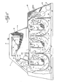
- FIG. 7 is a back cut-away view of the film processor.
- a divider wall 58 extends the length of the processor. It separates the chemical troughs from a back chamber which encloses components of the processor drive and control mechanism.
- Three sprockets 62 are supported on bearings in the divider wall 58 opposite the chemical troughs 17, 18 and 19.
- the hubs of the sprockets 62 contain sockets (not shown) for engagement with the matching splines 46 on the shafts 45 extending from each of the troughs.
- the sprockets 62 are engaged and rotated by a roller chain 61 which is driven by an electric motor 60.
- the divider wall 58 also supports a heater pad 65 adjacent the chemical troughs and a sensor 66 which controls the heater 65 by measuring the temperature of chemicals in one or more of the troughs.
- Proximity switch 25b is likewise mounted on the divider wall.
- Ambient air is drawn into the back chamber of the processor through intake louvers 64 by a fan 63.
- the air passes over an electric heater mesh 69 and through outlet louvers 28 into the drying chamber 20.
- Operation of the heater mesh 69 is controlled by a safety thermostatic element 70 which shuts down the heater mesh if air flow is shut off.
- the proximity switch 25b is activated when the dumper 24 is opened, to deposit a film carrier into the first trough, and then closed.
- a time delay circuit then continues to enable motor, heater mesh, and fan operation for a period of time sufficient to transport the carrier through the three troughs and for drying.
- the carrier is transported through all three troughs at a constant speed and the time delay circuit is operated for approximately 6.5 minutes.
- the motor may be provided with a speed control.
- the diameter of the drive sprockets 62 and/or 47 may be varied, from tank to tank, to decrease the time which the carrier spends in the successive troughs.
Landscapes
- Physics & Mathematics (AREA)
- General Physics & Mathematics (AREA)
- Photographic Processing Devices Using Wet Methods (AREA)
- Photographic Developing Apparatuses (AREA)
Applications Claiming Priority (2)
| Application Number | Priority Date | Filing Date | Title |
|---|---|---|---|
| US06/273,548 US4422748A (en) | 1981-06-15 | 1981-06-15 | Apparatus for transporting and processing photographic materials or the like |
| US273548 | 1999-03-22 |
Publications (3)
| Publication Number | Publication Date |
|---|---|
| EP0067486A2 EP0067486A2 (en) | 1982-12-22 |
| EP0067486A3 EP0067486A3 (en) | 1983-05-25 |
| EP0067486B1 true EP0067486B1 (en) | 1985-09-25 |
Family
ID=23044387
Family Applications (1)
| Application Number | Title | Priority Date | Filing Date |
|---|---|---|---|
| EP82200711A Expired EP0067486B1 (en) | 1981-06-15 | 1982-06-10 | Carrier transporting apparatus |
Country Status (8)
| Country | Link |
|---|---|
| US (1) | US4422748A (cg-RX-API-DMAC7.html) |
| EP (1) | EP0067486B1 (cg-RX-API-DMAC7.html) |
| JP (1) | JPS582842A (cg-RX-API-DMAC7.html) |
| BR (1) | BR8203472A (cg-RX-API-DMAC7.html) |
| CA (1) | CA1178100A (cg-RX-API-DMAC7.html) |
| DE (1) | DE3266517D1 (cg-RX-API-DMAC7.html) |
| ES (1) | ES513023A0 (cg-RX-API-DMAC7.html) |
| FI (1) | FI71025C (cg-RX-API-DMAC7.html) |
Families Citing this family (3)
| Publication number | Priority date | Publication date | Assignee | Title |
|---|---|---|---|---|
| US5311235A (en) * | 1992-03-02 | 1994-05-10 | Eastman Kodak Company | Driving mechanism for a photographic processing apparatus |
| US5483316A (en) * | 1994-07-08 | 1996-01-09 | Air Techniques, Inc. | Film chip transport assembly for film processing assembly |
| DE29800207U1 (de) * | 1998-01-09 | 1998-03-26 | Welp, Ulrich, Dr., 61231 Bad Nauheim | Schnellentwicklungsgerät für Zahnröntgenfilme |
Family Cites Families (9)
| Publication number | Priority date | Publication date | Assignee | Title |
|---|---|---|---|---|
| DE1252528B (cg-RX-API-DMAC7.html) * | 1967-10-19 | |||
| US3216342A (en) * | 1962-02-05 | 1965-11-09 | Pavelle Corp | Photographic processor |
| US3672289A (en) * | 1970-10-16 | 1972-06-27 | Xatron Corp | Automatic film processing apparatus |
| JPS5317058B2 (cg-RX-API-DMAC7.html) * | 1972-06-10 | 1978-06-06 | ||
| US3882525A (en) * | 1973-09-05 | 1975-05-06 | Ernst Zwettler | Automatic film processor for dental x-ray film |
| JPS5113241A (en) * | 1974-07-24 | 1976-02-02 | Noritsu Koki Co Ltd | Shashinkankozairyorenzokushorisochiniokeru isokenshorisokushinyorooraa |
| US4032943A (en) * | 1975-06-19 | 1977-06-28 | Pennwalt Corporation | Dental x-ray film processing system |
| US4112452A (en) * | 1977-03-07 | 1978-09-05 | Eastman Kodak Company | Apparatus for processing photographic film |
| US4125852A (en) * | 1977-05-31 | 1978-11-14 | Brooks Louis E | Dental film carriage |
-
1981
- 1981-06-15 US US06/273,548 patent/US4422748A/en not_active Expired - Fee Related
-
1982
- 1982-06-10 DE DE8282200711T patent/DE3266517D1/de not_active Expired
- 1982-06-10 EP EP82200711A patent/EP0067486B1/en not_active Expired
- 1982-06-10 CA CA000404899A patent/CA1178100A/en not_active Expired
- 1982-06-11 ES ES513023A patent/ES513023A0/es active Granted
- 1982-06-11 FI FI822101A patent/FI71025C/fi not_active IP Right Cessation
- 1982-06-14 JP JP57101939A patent/JPS582842A/ja active Granted
- 1982-06-14 BR BR8203472A patent/BR8203472A/pt unknown
Also Published As
| Publication number | Publication date |
|---|---|
| ES8306890A1 (es) | 1983-06-01 |
| JPS582842A (ja) | 1983-01-08 |
| DE3266517D1 (en) | 1985-10-31 |
| FI71025B (fi) | 1986-07-18 |
| CA1178100A (en) | 1984-11-20 |
| FI822101A0 (fi) | 1982-06-11 |
| EP0067486A2 (en) | 1982-12-22 |
| ES513023A0 (es) | 1983-06-01 |
| BR8203472A (pt) | 1983-06-07 |
| JPH0160139B2 (cg-RX-API-DMAC7.html) | 1989-12-21 |
| EP0067486A3 (en) | 1983-05-25 |
| US4422748A (en) | 1983-12-27 |
| FI71025C (fi) | 1986-10-27 |
Similar Documents
| Publication | Publication Date | Title |
|---|---|---|
| US4548130A (en) | Automatic food cooking machine | |
| US4178091A (en) | Horizontal film processing apparatus | |
| US4112452A (en) | Apparatus for processing photographic film | |
| EP0067486B1 (en) | Carrier transporting apparatus | |
| US4167320A (en) | Vertical film processing apparatus | |
| EP0062593B1 (fr) | Appareil automatique pour développer des films photographiques | |
| CA1052161A (en) | Photographic processor with magnetic film carriage and drive | |
| US2858763A (en) | Roasting machine for wieners | |
| EP0327084A2 (en) | Photographic film processor rack and tank assembly | |
| US3492932A (en) | Machine for processing photograph films and prints | |
| NL8302953A (nl) | Machine voor het ontwikkelen van filmschijven. | |
| US3413904A (en) | Film processor | |
| US4151657A (en) | Film dryer | |
| US1795220A (en) | Developing apparatus | |
| US4353635A (en) | Apparatus for automatically developing film | |
| CA1097120A (en) | Photographic processor that rotates film discs in processing solutions | |
| JP2550797Y2 (ja) | トンネル型乾燥炉 | |
| EP0105761B1 (en) | Dryer apparatus for film disc processor | |
| US3559556A (en) | Dental x-ray film processor and processing cassette | |
| US3292518A (en) | Device for processing photographic sheet material | |
| CA1063413A (en) | Photographic processor with magnetic film carriage drive | |
| CN110558782A (zh) | 一种图书管理用展列柜 | |
| US3152532A (en) | Apparatus for producing copies | |
| US3417687A (en) | Automatic film processing apparatus | |
| CA1126562A (en) | Horizontal processing of disc-shaped film elements |
Legal Events
| Date | Code | Title | Description |
|---|---|---|---|
| PUAI | Public reference made under article 153(3) epc to a published international application that has entered the european phase |
Free format text: ORIGINAL CODE: 0009012 |
|
| 17P | Request for examination filed |
Effective date: 19820610 |
|
| AK | Designated contracting states |
Designated state(s): BE DE FR GB IT SE |
|
| PUAL | Search report despatched |
Free format text: ORIGINAL CODE: 0009013 |
|
| AK | Designated contracting states |
Designated state(s): BE DE FR GB IT SE |
|
| ITF | It: translation for a ep patent filed | ||
| GRAA | (expected) grant |
Free format text: ORIGINAL CODE: 0009210 |
|
| AK | Designated contracting states |
Designated state(s): BE DE FR GB IT SE |
|
| REF | Corresponds to: |
Ref document number: 3266517 Country of ref document: DE Date of ref document: 19851031 |
|
| ET | Fr: translation filed | ||
| PLBE | No opposition filed within time limit |
Free format text: ORIGINAL CODE: 0009261 |
|
| STAA | Information on the status of an ep patent application or granted ep patent |
Free format text: STATUS: NO OPPOSITION FILED WITHIN TIME LIMIT |
|
| 26N | No opposition filed | ||
| PG25 | Lapsed in a contracting state [announced via postgrant information from national office to epo] |
Ref country code: SE Effective date: 19880611 |
|
| BERE | Be: lapsed |
Owner name: NORTH AMERICAN PHILIPS CORP. Effective date: 19880630 |
|
| PG25 | Lapsed in a contracting state [announced via postgrant information from national office to epo] |
Ref country code: FR Free format text: LAPSE BECAUSE OF NON-PAYMENT OF DUE FEES Effective date: 19890228 |
|
| REG | Reference to a national code |
Ref country code: FR Ref legal event code: ST |
|
| PG25 | Lapsed in a contracting state [announced via postgrant information from national office to epo] |
Ref country code: GB Effective date: 19890610 |
|
| PG25 | Lapsed in a contracting state [announced via postgrant information from national office to epo] |
Ref country code: BE Effective date: 19890630 |
|
| GBPC | Gb: european patent ceased through non-payment of renewal fee | ||
| PG25 | Lapsed in a contracting state [announced via postgrant information from national office to epo] |
Ref country code: DE Effective date: 19900301 |
|
| EUG | Se: european patent has lapsed |
Ref document number: 82200711.8 Effective date: 19890220 |