EP0067226A1 - D.c. generator type non-contact speed sensing device - Google Patents
D.c. generator type non-contact speed sensing device Download PDFInfo
- Publication number
- EP0067226A1 EP0067226A1 EP81902593A EP81902593A EP0067226A1 EP 0067226 A1 EP0067226 A1 EP 0067226A1 EP 81902593 A EP81902593 A EP 81902593A EP 81902593 A EP81902593 A EP 81902593A EP 0067226 A1 EP0067226 A1 EP 0067226A1
- Authority
- EP
- European Patent Office
- Prior art keywords
- magnet
- detecting device
- speed detecting
- generator type
- permanent magnet
- Prior art date
- Legal status (The legal status is an assumption and is not a legal conclusion. Google has not performed a legal analysis and makes no representation as to the accuracy of the status listed.)
- Withdrawn
Links
Images


Classifications
-
- H—ELECTRICITY
- H02—GENERATION; CONVERSION OR DISTRIBUTION OF ELECTRIC POWER
- H02K—DYNAMO-ELECTRIC MACHINES
- H02K21/00—Synchronous motors having permanent magnets; Synchronous generators having permanent magnets
- H02K21/12—Synchronous motors having permanent magnets; Synchronous generators having permanent magnets with stationary armatures and rotating magnets
- H02K21/14—Synchronous motors having permanent magnets; Synchronous generators having permanent magnets with stationary armatures and rotating magnets with magnets rotating within the armatures
-
- G—PHYSICS
- G01—MEASURING; TESTING
- G01R—MEASURING ELECTRIC VARIABLES; MEASURING MAGNETIC VARIABLES
- G01R31/00—Arrangements for testing electric properties; Arrangements for locating electric faults; Arrangements for electrical testing characterised by what is being tested not provided for elsewhere
- G01R31/34—Testing dynamo-electric machines
-
- G—PHYSICS
- G01—MEASURING; TESTING
- G01P—MEASURING LINEAR OR ANGULAR SPEED, ACCELERATION, DECELERATION, OR SHOCK; INDICATING PRESENCE, ABSENCE, OR DIRECTION, OF MOVEMENT
- G01P3/00—Measuring linear or angular speed; Measuring differences of linear or angular speeds
- G01P3/42—Devices characterised by the use of electric or magnetic means
- G01P3/44—Devices characterised by the use of electric or magnetic means for measuring angular speed
- G01P3/46—Devices characterised by the use of electric or magnetic means for measuring angular speed by measuring amplitude of generated current or voltage
- G01P3/465—Devices characterised by the use of electric or magnetic means for measuring angular speed by measuring amplitude of generated current or voltage by using dynamo-electro tachometers or electric generator
-
- G—PHYSICS
- G01—MEASURING; TESTING
- G01P—MEASURING LINEAR OR ANGULAR SPEED, ACCELERATION, DECELERATION, OR SHOCK; INDICATING PRESENCE, ABSENCE, OR DIRECTION, OF MOVEMENT
- G01P3/00—Measuring linear or angular speed; Measuring differences of linear or angular speeds
- G01P3/42—Devices characterised by the use of electric or magnetic means
- G01P3/44—Devices characterised by the use of electric or magnetic means for measuring angular speed
- G01P3/48—Devices characterised by the use of electric or magnetic means for measuring angular speed by measuring frequency of generated current or voltage
- G01P3/481—Devices characterised by the use of electric or magnetic means for measuring angular speed by measuring frequency of generated current or voltage of pulse signals
- G01P3/487—Devices characterised by the use of electric or magnetic means for measuring angular speed by measuring frequency of generated current or voltage of pulse signals delivered by rotating magnets
-
- H—ELECTRICITY
- H02—GENERATION; CONVERSION OR DISTRIBUTION OF ELECTRIC POWER
- H02K—DYNAMO-ELECTRIC MACHINES
- H02K1/00—Details of the magnetic circuit
- H02K1/06—Details of the magnetic circuit characterised by the shape, form or construction
- H02K1/22—Rotating parts of the magnetic circuit
- H02K1/27—Rotor cores with permanent magnets
- H02K1/2706—Inner rotors
- H02K1/2713—Inner rotors the magnetisation axis of the magnets being axial, e.g. claw-pole type
Definitions
- the present invention relates to a non-contacting speed detecting device of a direct-current generator type, and especially to the above-mentioned device which uses a yoke member in order to equalize the distribution of the magnetic flux density in the magnetic pole of the rotator.
- a non-contacting speed detecting device of a DC generator type a device wherein a generator, comprising a rotator consisting of a cylidrical permanent magnet having a plurality of magnetic poles along the circumferential direction and stator windings arranged along the circumference of said rotator, is designed to gain a DC voltage by switching multi-phased trapezoidal waveform AC voltages obtained from the respective phases of the stator windings in their flat portions.
- a rotator l' consists of a permanent magnet having four magnetic poles in its circumferential face and its axis is coupled to the axis of a rotating body to be measured.
- a stator 2 has a stator core and four phases of stator windings W 1 , W 2 , W3 and W 4 wound through the slot portions of said stator core.
- V 1 , V 2 , V 3 and V 4 are produced in the respective phases W 1 , W 2 ' W 3 and W 4 of the windings wound in the stator.
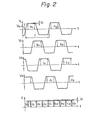
- the waveforms of the respective phases are shifted by 90° in phase in the order of V 1 , V 2 , V3 and V 4 .
- Each of the waveforms has an approximately trapezoidal shape in half of each cycle, as shown in Fig. 2. Accordingly, the value of the voltage is an approximately constant value V 0 in the central portion of said trapezoidal waveform. Furthermore, this constant voltage value V 0 is directly proportional to the rotating speed of the rotator 1'.
- the cycle time T of each waveform is inversely proportional to the rotating speed of the rotator I'.
- a voltage variance Vr of about 5% occurs because of the following reason.
- the distribution of the magnetic flux density near the stator winding W1 wound in the slot 3 is shown in Fig. 1 (B) and (C), in which Fig. 1 (B) illustrates the case where a portion in which the magnetic flux density, being relatively high, passes near the winding and Fig. 1 (C) illustrates the case where a portion in which the magnetic flux density, being relatively low, passes near the winding.
- Fig. 1 (B) illustrates the case where a portion in which the magnetic flux density, being relatively high, passes near the winding
- Fig. 1 (C) illustrates the case where a portion in which the magnetic flux density, being relatively low, passes near the winding.
- the main object of the present invention is to minimize the above-mentioned problem in the prior art, on the basis of the idea of equalizing the distribution of the magnetic flux density on the surface of the magnetic pole of the rotator by using, as a stator, such a structure in which yokes, having a desired pole number of magnetic poles, are attached to a permanent magnet having its polarity along its axis direction; to remove the variance component in the output voltage of a non-contacting speed detecting device of a DC generator type, which is generated by the inequality of the magnetic flux; and to improve the precision of the speed detection.
- a non-contacting speed detecting device of a DC generator type comprising a cylindrical rotater magnet having an alternating distribution of the N and S poles along the circumferential direction, a stator opposite to said rotator magnet, and stator windings wound in said stator, wherein a permanent magnetic, having its polarity along the axial direction, is used for said rotator magnet, a yoke member extending from the ends of said permanent magnet in its axial direction to the positions at which said yoke covers the lateral circumferential surface of said permanent magnet is formed, and said stator windings are arranged so that they face said yoke member.
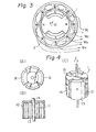
- a non-contacting speed detecting device of a DC generator type in accordance with one embodiment of the present invention, is illustrated in Fig. 3 and Figs. 4 (A), (B) and (C).
- a rotator 1 according to the present invention and a stator 2 in which windings W 1 , W 2 , W3 and W 4 are wound are illustrated.
- Figs. 4 (A), (B) and (C) the structure of the rotator 1 of Fig. 3 is illustrated in detail.
- the rotator 1 consists of a permanent magnet 11, a yoke member 12 of the N pole side, a yoke member 13 of the S pole side and a rotation axis 14.
- the yoke members 12, 13 of the N and S pole sides have the same shapes, and each has a flat plane portion 15 contacting the magnetic pole surface of the permanent magnet 11, and a magnetic pole portion 16 vertical to the flat plane portion 15 and extending in a fashion so that it covers the lateral circumferential surface of the permanent magnet.
- This magnetic pole portion 16 is arranged to form the N poles and the S poles alternatively in the cylindrical surface coaxial to the permanent magnet 11.
- the speed detecting device of Fig. 3 differs from the speed detecing device of a prior art of Fig. 1 in the point that the magnet pole portion of the stator 1, which portion is opposite to the stator, is formed from the yoke member. In Figs.
- FIG. 5 (A) and (B) the distribution of the magnetic flux density produced between the magnetic pole portion 16 formed from the yoke and the stator core 2 is illustrated.
- Fig. 5 (A) the distribution of the magnetic flux density on the surface of the magnetic pole of the rotator is given from the end magnetic pole surface of the permanent magnet 11 through the magnetic material forming the yoke, and, therefore, it is equalized.
- Fig. 5 (B) the distribution of the magnetic flux density between the rotator 1 and the stator 2, which distribution is equalized according to the present invention, is illustrated.
- the voltage variance in the output waveform of each phase shown in Fig. 2 in the case of the speed detecting device of a prior art, can be decreased remarkably. Therefore, the finally obtained output voltage of the speed detecting device has a DC waveform in which the variance component is extremely small for a constant rotating speed.
- the device in which the number of the magnetic poles of the rotator is four, is described; however, of course the number of the magnetic poles of the rotator may be two or six.
- the distribution of the magnetic flux density between the magnetic pole portion of the rotator and the stator core can be equalized and the variance component of the output voltage can be removed, so that the precision of the speed detecting can be improved.
Abstract
In a D.C. generator type non-contact speed sensing device comprising a cylindrical magnet-rotor with N and S poles alternating around the periphery and a stator with windings wound confronting the rotor, the non-uniformity in the magnetization of the magnet causes the non-uniformity in the magnetic flux density in the vicinity of the surface of the pole, so that the electromotive force induced in the windings fluctuates, resulting in an inaccurate speed sensing. To overcome the problem, a rotor is constructed out of a permanent magnet (11) with magnetic poles aligned with the axial direction and yoke members (12), (13) each of which is composed of a plane portion (15) in contact with the pole-surface of the magnet and an elongated portion (16) normal to the plane portion and of such a form as covers the peripheral surface of the side-portion of the magnet. Thus, the magnetic flux density over the surface of the yoke is made uniform and the fluctuation in the electromotive force induced in the windings, caused by the non-uniformity in magnetization, is eliminated.
Description
- The present invention relates to a non-contacting speed detecting device of a direct-current generator type, and especially to the above-mentioned device which uses a yoke member in order to equalize the distribution of the magnetic flux density in the magnetic pole of the rotator.
- Conventionally, there is known as a non-contacting speed detecting device of a DC generator type, a device wherein a generator, comprising a rotator consisting of a cylidrical permanent magnet having a plurality of magnetic poles along the circumferential direction and stator windings arranged along the circumference of said rotator, is designed to gain a DC voltage by switching multi-phased trapezoidal waveform AC voltages obtained from the respective phases of the stator windings in their flat portions.
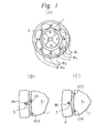
- The above-mentioned speed detecting device of a prior art is illustrated in Fig. 1 (A), (B) and (C). Various voltage waveforms in the speed detecting device of Fig. 1 are illustrated in Fig. 2. In Fig. 1 (A), a rotator l' consists of a permanent magnet having four magnetic poles in its circumferential face and its axis is coupled to the axis of a rotating body to be measured. A
stator 2 has a stator core and four phases of stator windings W1 , W2 , W3 and W4 wound through the slot portions of said stator core. When the rotator 1' rotates in the direction of the arrow r, shown in Fig. 1, alternating voltages, shown in Fig. 2 as V1 , V2 , V3 and V4 , are produced in the respective phases W1 , W 2 ' W3 and W4 of the windings wound in the stator. The waveforms of the respective phases are shifted by 90° in phase in the order of V1 , V2 , V3 and V4. Each of the waveforms has an approximately trapezoidal shape in half of each cycle, as shown in Fig. 2. Accordingly, the value of the voltage is an approximately constant value V0 in the central portion of said trapezoidal waveform. Furthermore, this constant voltage value V0 is directly proportional to the rotating speed of the rotator 1'. The cycle time T of each waveform is inversely proportional to the rotating speed of the rotator I'. By switching selectively only the above-mentioned portions where the voltage value is constant in the waveform of each phase and inputing said portions into an amplifier circuit, a DC voltage output proportional to the rotating speed of the rotator 1' is obtained. The output waveform, obtained in the above--mentioned manner, is shown as E in Fig. 2. At the portion where the outputs of two phases are overlapped, the output voltage is adjusted to become the mean value between these output voltages of two phases. The variance component, existing in the flat portion of the waveform of each phase, appears in the above-mentioned DC output waveform as shown in E of Fig. 2. - By the way, in the speed detecting device of Fig. 1, a voltage variance Vr of about 5% occurs because of the following reason. There is an inequality of the magnetization in the magnetic pole of the permanent magnet, generally due to the manufacturing method, and, therefore, there also occurs an inequality in the distribution of the magnetic flux density on the surface of the magnetic pole. The distribution of the magnetic flux density near the stator winding W1 wound in the
slot 3 is shown in Fig. 1 (B) and (C), in which Fig. 1 (B) illustrates the case where a portion in which the magnetic flux density, being relatively high, passes near the winding and Fig. 1 (C) illustrates the case where a portion in which the magnetic flux density, being relatively low, passes near the winding. In Fig. 1 (B) and 1 (C), 101, 102, 103 and 104 indicate portions where the magnetization is relatively great. When the rotator 1' rotates at a constant speed, the electromotive force generated in the stator winding in the case of Fig. 1 (B) is greater than that in the case of Fig. 1 (C). Therefore, a variance according to the inequality in the magnet occurs in the voltage signal E indicating the speed, so that the detection of the speed becomes inaccurate. This variance causes trouble, especially when a very small speed is detected. In order to improve this problem, there is proposed a structure in which a pole shoe is attached to the magnetic pole portion of the rotator; however, the inequality of the magnetic flux density cannot be removed completely by this means. - The main object of the present invention is to minimize the above-mentioned problem in the prior art, on the basis of the idea of equalizing the distribution of the magnetic flux density on the surface of the magnetic pole of the rotator by using, as a stator, such a structure in which yokes, having a desired pole number of magnetic poles, are attached to a permanent magnet having its polarity along its axis direction; to remove the variance component in the output voltage of a non-contacting speed detecting device of a DC generator type, which is generated by the inequality of the magnetic flux; and to improve the precision of the speed detection.
- In accordance with the present invention, there is provided a non-contacting speed detecting device of a DC generator type, comprising a cylindrical rotater magnet having an alternating distribution of the N and S poles along the circumferential direction, a stator opposite to said rotator magnet, and stator windings wound in said stator, wherein a permanent magnetic, having its polarity along the axial direction, is used for said rotator magnet, a yoke member extending from the ends of said permanent magnet in its axial direction to the positions at which said yoke covers the lateral circumferential surface of said permanent magnet is formed, and said stator windings are arranged so that they face said yoke member.
-
- Figs. 1 (A), (B) and (C) illustrate a non-contacting speed detecting device of a DC generator type of a prior art;
- Fig. 2 illustrates various voltage waveforms in the speed detecting device in Fig. 1;
- Fig. 3 illustrates a non-contacting speed detecting device of a DC generator type in accordance with one embodiment of the present invention;
- Figs. 4 (A), (B) and (C) illustrate the structure of the rotator used in the speed detecting device of Fig. 3; and
- Figs. 5 (A) and (B) illustrate the distribution of the magnetic flux density between the magnetic pole of the rotator and the stator core in the speed detecting device of Fig. 3.
- A non-contacting speed detecting device of a DC generator type, in accordance with one embodiment of the present invention, is illustrated in Fig. 3 and Figs. 4 (A), (B) and (C).
- In Fig. 3, a rotator 1 according to the present invention and a stator 2 in which windings W1 , W2 , W3 and W4 are wound, are illustrated. In Figs. 4 (A), (B) and (C), the structure of the rotator 1 of Fig. 3 is illustrated in detail. The rotator 1 consists of a
permanent magnet 11, ayoke member 12 of the N pole side, ayoke member 13 of the S pole side and arotation axis 14. Theyoke members flat plane portion 15 contacting the magnetic pole surface of thepermanent magnet 11, and amagnetic pole portion 16 vertical to theflat plane portion 15 and extending in a fashion so that it covers the lateral circumferential surface of the permanent magnet. Thismagnetic pole portion 16 is arranged to form the N poles and the S poles alternatively in the cylindrical surface coaxial to thepermanent magnet 11. The speed detecting device of Fig. 3 differs from the speed detecing device of a prior art of Fig. 1 in the point that the magnet pole portion of the stator 1, which portion is opposite to the stator, is formed from the yoke member. In Figs. 5 (A) and (B), the distribution of the magnetic flux density produced between themagnetic pole portion 16 formed from the yoke and thestator core 2 is illustrated. As illustrated in Fig. 5 (A), the distribution of the magnetic flux density on the surface of the magnetic pole of the rotator is given from the end magnetic pole surface of thepermanent magnet 11 through the magnetic material forming the yoke, and, therefore, it is equalized. In Fig. 5 (B), the distribution of the magnetic flux density between the rotator 1 and thestator 2, which distribution is equalized according to the present invention, is illustrated. - In accordance with the speed detecting device according to the present invention illustrated in Fig. 3, the voltage variance in the output waveform of each phase shown in Fig. 2, in the case of the speed detecting device of a prior art, can be decreased remarkably. Therefore, the finally obtained output voltage of the speed detecting device has a DC waveform in which the variance component is extremely small for a constant rotating speed.
- Furthermore, in the above-mentioned embodiment, the device, in which the number of the magnetic poles of the rotator is four, is described; however, of course the number of the magnetic poles of the rotator may be two or six.
- According to the present invention, in the non--contacting speed detecting device of a DC generator type, the distribution of the magnetic flux density between the magnetic pole portion of the rotator and the stator core can be equalized and the variance component of the output voltage can be removed, so that the precision of the speed detecting can be improved.
Claims (6)
1. A non-contacting speed detecting device of a direct-current generator type, comprising a cylindrical rotator magnet having an alternating distribution of the N and S poles along the circumferential direction, a stator opposite to said rotator magnet, and stator windings wound on said stator; wherein a permanent magnet, having its polarity along its axial direction, is used for said rotator magnet; a yoke member, extending from the ends of the axial direction of said permanent magnet to the position at which said yoke covers the lateral circumferential surface of said permanent magnet, is formed; and said stator windings are arranged so that they face said yoke member.
2. A non-contacting speed detecting device of a direct-current generator type as claimed in Claim 1, wherein said yoke member comprises a flat plane portion contacting the end of the axial direction of said permanent magnet and a magnetic pole portion of a predetermined pole number arranged in the fashion that said portion covers the lateral circumferential surface of said permanent magnet.
3. A non-contacting speed detecting device of a direct-current generator type as claimed in Claim 2, wherein said predetermined pole number of said yoke member is 2.
4. A non-contacting speed detecting device of a direct-current generator type as claimed in Claim 2, wherein said predetermined pole number of said yoke member is 4.
5. A non-contacting speed detecting device of a direct-current generator type as claimed in Claim 2, wherein said predetermined pole number of said yoke member is 6.
6. A non-contacting speed detecting device of a direct-current generator type as claimed in anyone of Claims 1 through 5, wherein two sections of said yoke member, extending respectively from the N pole and the S pole ends of said permanent magnet, have the same shape.
Applications Claiming Priority (2)
| Application Number | Priority Date | Filing Date | Title |
|---|---|---|---|
| JP55127878A JPS608461B2 (en) | 1980-09-17 | 1980-09-17 | DC generator type non-contact speed detection device |
| JP127878/80 | 1980-09-17 |
Publications (2)
| Publication Number | Publication Date |
|---|---|
| EP0067226A1 true EP0067226A1 (en) | 1982-12-22 |
| EP0067226A4 EP0067226A4 (en) | 1984-11-22 |
Family
ID=14970869
Family Applications (1)
| Application Number | Title | Priority Date | Filing Date |
|---|---|---|---|
| EP19810902593 Withdrawn EP0067226A4 (en) | 1980-09-17 | 1981-09-16 | D.c. generator type non-contact speed sensing device. |
Country Status (4)
| Country | Link |
|---|---|
| EP (1) | EP0067226A4 (en) |
| JP (1) | JPS608461B2 (en) |
| KR (1) | KR860000049B1 (en) |
| WO (1) | WO1982001073A1 (en) |
Cited By (2)
| Publication number | Priority date | Publication date | Assignee | Title |
|---|---|---|---|---|
| EP0216998A1 (en) * | 1985-08-27 | 1987-04-08 | Hübner Elektromaschinen AG | Brushless induction machine |
| FR3114654A1 (en) * | 2020-09-28 | 2022-04-01 | Safran Electronics & Defense | Rotation speed measuring device and landing gear fitted with such a device |
Families Citing this family (2)
| Publication number | Priority date | Publication date | Assignee | Title |
|---|---|---|---|---|
| JPS6038159U (en) * | 1983-08-22 | 1985-03-16 | 大洋技研工業株式会社 | fuel cock |
| CN109738795B (en) * | 2018-12-09 | 2023-06-09 | 西安航天精密机电研究所 | Multistage motor rotor magnetic pole detection device |
Citations (3)
| Publication number | Priority date | Publication date | Assignee | Title |
|---|---|---|---|---|
| GB499042A (en) * | 1936-12-19 | 1939-01-18 | An Sfruttamento Brevetti Elett | Improvements in or relating to permanent magnets for magnetos |
| CH359772A (en) * | 1957-04-08 | 1962-01-31 | Licentia Gmbh | Permanent magnetic rotor, especially for small synchronous motors |
| US3806785A (en) * | 1969-06-10 | 1974-04-23 | Anvar | Brushless d. c. electric machine |
Family Cites Families (9)
| Publication number | Priority date | Publication date | Assignee | Title |
|---|---|---|---|---|
| US2836743A (en) * | 1956-01-25 | 1958-05-27 | Westinghouse Electric Corp | Permanent magnet rotor |
| GB913170A (en) * | 1959-10-09 | 1962-12-19 | Ferranti Ltd | Improvements relating to direct current tachometer generators |
| US3646376A (en) * | 1970-05-01 | 1972-02-29 | Gen Electric | High-frequency tachometer generator |
| DE2330309C3 (en) * | 1973-06-14 | 1978-04-13 | Siemens Ag, 1000 Berlin Und 8000 Muenchen | Circuit arrangement for speed control of a brushless DC motor |
| JPS5071365A (en) * | 1973-10-24 | 1975-06-13 | ||
| JPS5443754Y2 (en) * | 1975-08-07 | 1979-12-17 | ||
| JPS5366980U (en) * | 1976-11-06 | 1978-06-05 | ||
| US4088943A (en) * | 1977-02-25 | 1978-05-09 | Electro-Craft Corporation | Brushless DC tachometer circuit |
| JPS5614951A (en) * | 1979-07-19 | 1981-02-13 | Fanuc Ltd | Tachometer generator |
-
1980
- 1980-09-17 JP JP55127878A patent/JPS608461B2/en not_active Expired
-
1981
- 1981-09-15 KR KR1019810003421A patent/KR860000049B1/en active
- 1981-09-16 EP EP19810902593 patent/EP0067226A4/en not_active Withdrawn
- 1981-09-16 WO PCT/JP1981/000233 patent/WO1982001073A1/en not_active Application Discontinuation
Patent Citations (3)
| Publication number | Priority date | Publication date | Assignee | Title |
|---|---|---|---|---|
| GB499042A (en) * | 1936-12-19 | 1939-01-18 | An Sfruttamento Brevetti Elett | Improvements in or relating to permanent magnets for magnetos |
| CH359772A (en) * | 1957-04-08 | 1962-01-31 | Licentia Gmbh | Permanent magnetic rotor, especially for small synchronous motors |
| US3806785A (en) * | 1969-06-10 | 1974-04-23 | Anvar | Brushless d. c. electric machine |
Non-Patent Citations (1)
| Title |
|---|
| See also references of WO8201073A1 * |
Cited By (2)
| Publication number | Priority date | Publication date | Assignee | Title |
|---|---|---|---|---|
| EP0216998A1 (en) * | 1985-08-27 | 1987-04-08 | Hübner Elektromaschinen AG | Brushless induction machine |
| FR3114654A1 (en) * | 2020-09-28 | 2022-04-01 | Safran Electronics & Defense | Rotation speed measuring device and landing gear fitted with such a device |
Also Published As
| Publication number | Publication date |
|---|---|
| JPS608461B2 (en) | 1985-03-02 |
| KR860000049B1 (en) | 1986-01-30 |
| WO1982001073A1 (en) | 1982-04-01 |
| KR830008175A (en) | 1983-11-16 |
| JPS5752864A (en) | 1982-03-29 |
| EP0067226A4 (en) | 1984-11-22 |
Similar Documents
| Publication | Publication Date | Title |
|---|---|---|
| US4260920A (en) | Multi-pole permanent magnet rotor | |
| US4329636A (en) | Rotation sensor device | |
| US5382853A (en) | Brushless DC drive motor with external rotor for use in disc drives and like devices | |
| US4874975A (en) | Brushless DC motor | |
| US3855525A (en) | Angular velocity sensor | |
| US4217508A (en) | DC motor | |
| US4882511A (en) | Brushless three-phase D.C. motor | |
| US4283644A (en) | DC Motor | |
| GB1459982A (en) | Asymmetrically magnetized permanent magnet and a pulse generator utilizing the same | |
| KR920002692B1 (en) | Brushless d.c. motor | |
| US3809936A (en) | Brushless generator | |
| US4659953A (en) | Magnetic structure for synchro and tachometer | |
| US4495464A (en) | Non-contacting, speed-detecting device of a direct-current generator type | |
| EP0174290A1 (en) | Magnetic structure for synchro and tachometer | |
| US5070264A (en) | Position sensor | |
| JPS6179105A (en) | Diametral displacement magnetic detector for rotor | |
| US3512025A (en) | Discoidal electrodynamic motor | |
| EP0067226A1 (en) | D.c. generator type non-contact speed sensing device | |
| KR102167435B1 (en) | Electric motor | |
| Enokizono et al. | Distribution of two-dimensional magnetic properties in three-phase induction motor model core | |
| US3738175A (en) | Device for detecting the thermal overloads of a rotating member | |
| US7049723B2 (en) | DC motor | |
| JPS6031005A (en) | Detector of position of rotary angle | |
| EP0060894A1 (en) | D.c. generator type non-contact speed sensing device | |
| US5038099A (en) | Radial air-core gauge |
Legal Events
| Date | Code | Title | Description |
|---|---|---|---|
| PUAI | Public reference made under article 153(3) epc to a published international application that has entered the european phase |
Free format text: ORIGINAL CODE: 0009012 |
|
| 17P | Request for examination filed |
Effective date: 19820514 |
|
| AK | Designated contracting states |
Designated state(s): DE FR GB |
|
| STAA | Information on the status of an ep patent application or granted ep patent |
Free format text: STATUS: THE APPLICATION IS DEEMED TO BE WITHDRAWN |
|
| 18D | Application deemed to be withdrawn |
Effective date: 19861008 |
|
| RIN1 | Information on inventor provided before grant (corrected) |
Inventor name: IWAMATSU, NOBORU Inventor name: AMEMIYA, YOICHI Inventor name: KOZAI, YOSHINORI |