EP0067226A1 - Dispositif de detection de vitesse sans contact du type a generateur a courant continu - Google Patents
Dispositif de detection de vitesse sans contact du type a generateur a courant continu Download PDFInfo
- Publication number
- EP0067226A1 EP0067226A1 EP81902593A EP81902593A EP0067226A1 EP 0067226 A1 EP0067226 A1 EP 0067226A1 EP 81902593 A EP81902593 A EP 81902593A EP 81902593 A EP81902593 A EP 81902593A EP 0067226 A1 EP0067226 A1 EP 0067226A1
- Authority
- EP
- European Patent Office
- Prior art keywords
- magnet
- detecting device
- speed detecting
- generator type
- permanent magnet
- Prior art date
- Legal status (The legal status is an assumption and is not a legal conclusion. Google has not performed a legal analysis and makes no representation as to the accuracy of the status listed.)
- Withdrawn
Links
Images


Classifications
-
- H—ELECTRICITY
- H02—GENERATION; CONVERSION OR DISTRIBUTION OF ELECTRIC POWER
- H02K—DYNAMO-ELECTRIC MACHINES
- H02K21/00—Synchronous motors having permanent magnets; Synchronous generators having permanent magnets
- H02K21/12—Synchronous motors having permanent magnets; Synchronous generators having permanent magnets with stationary armatures and rotating magnets
- H02K21/14—Synchronous motors having permanent magnets; Synchronous generators having permanent magnets with stationary armatures and rotating magnets with magnets rotating within the armatures
-
- G—PHYSICS
- G01—MEASURING; TESTING
- G01R—MEASURING ELECTRIC VARIABLES; MEASURING MAGNETIC VARIABLES
- G01R31/00—Arrangements for testing electric properties; Arrangements for locating electric faults; Arrangements for electrical testing characterised by what is being tested not provided for elsewhere
- G01R31/34—Testing dynamo-electric machines
-
- G—PHYSICS
- G01—MEASURING; TESTING
- G01P—MEASURING LINEAR OR ANGULAR SPEED, ACCELERATION, DECELERATION, OR SHOCK; INDICATING PRESENCE, ABSENCE, OR DIRECTION, OF MOVEMENT
- G01P3/00—Measuring linear or angular speed; Measuring differences of linear or angular speeds
- G01P3/42—Devices characterised by the use of electric or magnetic means
- G01P3/44—Devices characterised by the use of electric or magnetic means for measuring angular speed
- G01P3/46—Devices characterised by the use of electric or magnetic means for measuring angular speed by measuring amplitude of generated current or voltage
- G01P3/465—Devices characterised by the use of electric or magnetic means for measuring angular speed by measuring amplitude of generated current or voltage by using dynamo-electro tachometers or electric generator
-
- G—PHYSICS
- G01—MEASURING; TESTING
- G01P—MEASURING LINEAR OR ANGULAR SPEED, ACCELERATION, DECELERATION, OR SHOCK; INDICATING PRESENCE, ABSENCE, OR DIRECTION, OF MOVEMENT
- G01P3/00—Measuring linear or angular speed; Measuring differences of linear or angular speeds
- G01P3/42—Devices characterised by the use of electric or magnetic means
- G01P3/44—Devices characterised by the use of electric or magnetic means for measuring angular speed
- G01P3/48—Devices characterised by the use of electric or magnetic means for measuring angular speed by measuring frequency of generated current or voltage
- G01P3/481—Devices characterised by the use of electric or magnetic means for measuring angular speed by measuring frequency of generated current or voltage of pulse signals
- G01P3/487—Devices characterised by the use of electric or magnetic means for measuring angular speed by measuring frequency of generated current or voltage of pulse signals delivered by rotating magnets
-
- H—ELECTRICITY
- H02—GENERATION; CONVERSION OR DISTRIBUTION OF ELECTRIC POWER
- H02K—DYNAMO-ELECTRIC MACHINES
- H02K1/00—Details of the magnetic circuit
- H02K1/06—Details of the magnetic circuit characterised by the shape, form or construction
- H02K1/22—Rotating parts of the magnetic circuit
- H02K1/27—Rotor cores with permanent magnets
- H02K1/2706—Inner rotors
- H02K1/2713—Inner rotors the magnetisation axis of the magnets being axial, e.g. claw-pole type
Definitions
- the present invention relates to a non-contacting speed detecting device of a direct-current generator type, and especially to the above-mentioned device which uses a yoke member in order to equalize the distribution of the magnetic flux density in the magnetic pole of the rotator.
- a non-contacting speed detecting device of a DC generator type a device wherein a generator, comprising a rotator consisting of a cylidrical permanent magnet having a plurality of magnetic poles along the circumferential direction and stator windings arranged along the circumference of said rotator, is designed to gain a DC voltage by switching multi-phased trapezoidal waveform AC voltages obtained from the respective phases of the stator windings in their flat portions.
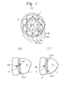
- a rotator l' consists of a permanent magnet having four magnetic poles in its circumferential face and its axis is coupled to the axis of a rotating body to be measured.
- a stator 2 has a stator core and four phases of stator windings W 1 , W 2 , W3 and W 4 wound through the slot portions of said stator core.
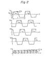
- V 1 , V 2 , V 3 and V 4 are produced in the respective phases W 1 , W 2 ' W 3 and W 4 of the windings wound in the stator.
- the waveforms of the respective phases are shifted by 90° in phase in the order of V 1 , V 2 , V3 and V 4 .
- Each of the waveforms has an approximately trapezoidal shape in half of each cycle, as shown in Fig. 2. Accordingly, the value of the voltage is an approximately constant value V 0 in the central portion of said trapezoidal waveform. Furthermore, this constant voltage value V 0 is directly proportional to the rotating speed of the rotator 1'.
- the cycle time T of each waveform is inversely proportional to the rotating speed of the rotator I'.
- a voltage variance Vr of about 5% occurs because of the following reason.
- the distribution of the magnetic flux density near the stator winding W1 wound in the slot 3 is shown in Fig. 1 (B) and (C), in which Fig. 1 (B) illustrates the case where a portion in which the magnetic flux density, being relatively high, passes near the winding and Fig. 1 (C) illustrates the case where a portion in which the magnetic flux density, being relatively low, passes near the winding.
- Fig. 1 (B) illustrates the case where a portion in which the magnetic flux density, being relatively high, passes near the winding
- Fig. 1 (C) illustrates the case where a portion in which the magnetic flux density, being relatively low, passes near the winding.
- the main object of the present invention is to minimize the above-mentioned problem in the prior art, on the basis of the idea of equalizing the distribution of the magnetic flux density on the surface of the magnetic pole of the rotator by using, as a stator, such a structure in which yokes, having a desired pole number of magnetic poles, are attached to a permanent magnet having its polarity along its axis direction; to remove the variance component in the output voltage of a non-contacting speed detecting device of a DC generator type, which is generated by the inequality of the magnetic flux; and to improve the precision of the speed detection.
- a non-contacting speed detecting device of a DC generator type comprising a cylindrical rotater magnet having an alternating distribution of the N and S poles along the circumferential direction, a stator opposite to said rotator magnet, and stator windings wound in said stator, wherein a permanent magnetic, having its polarity along the axial direction, is used for said rotator magnet, a yoke member extending from the ends of said permanent magnet in its axial direction to the positions at which said yoke covers the lateral circumferential surface of said permanent magnet is formed, and said stator windings are arranged so that they face said yoke member.
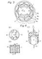
- a non-contacting speed detecting device of a DC generator type in accordance with one embodiment of the present invention, is illustrated in Fig. 3 and Figs. 4 (A), (B) and (C).
- a rotator 1 according to the present invention and a stator 2 in which windings W 1 , W 2 , W3 and W 4 are wound are illustrated.
- Figs. 4 (A), (B) and (C) the structure of the rotator 1 of Fig. 3 is illustrated in detail.
- the rotator 1 consists of a permanent magnet 11, a yoke member 12 of the N pole side, a yoke member 13 of the S pole side and a rotation axis 14.
- the yoke members 12, 13 of the N and S pole sides have the same shapes, and each has a flat plane portion 15 contacting the magnetic pole surface of the permanent magnet 11, and a magnetic pole portion 16 vertical to the flat plane portion 15 and extending in a fashion so that it covers the lateral circumferential surface of the permanent magnet.
- This magnetic pole portion 16 is arranged to form the N poles and the S poles alternatively in the cylindrical surface coaxial to the permanent magnet 11.
- the speed detecting device of Fig. 3 differs from the speed detecing device of a prior art of Fig. 1 in the point that the magnet pole portion of the stator 1, which portion is opposite to the stator, is formed from the yoke member. In Figs.
- FIG. 5 (A) and (B) the distribution of the magnetic flux density produced between the magnetic pole portion 16 formed from the yoke and the stator core 2 is illustrated.
- Fig. 5 (A) the distribution of the magnetic flux density on the surface of the magnetic pole of the rotator is given from the end magnetic pole surface of the permanent magnet 11 through the magnetic material forming the yoke, and, therefore, it is equalized.
- Fig. 5 (B) the distribution of the magnetic flux density between the rotator 1 and the stator 2, which distribution is equalized according to the present invention, is illustrated.
- the voltage variance in the output waveform of each phase shown in Fig. 2 in the case of the speed detecting device of a prior art, can be decreased remarkably. Therefore, the finally obtained output voltage of the speed detecting device has a DC waveform in which the variance component is extremely small for a constant rotating speed.
- the device in which the number of the magnetic poles of the rotator is four, is described; however, of course the number of the magnetic poles of the rotator may be two or six.
- the distribution of the magnetic flux density between the magnetic pole portion of the rotator and the stator core can be equalized and the variance component of the output voltage can be removed, so that the precision of the speed detecting can be improved.
Landscapes
- Physics & Mathematics (AREA)
- General Physics & Mathematics (AREA)
- Engineering & Computer Science (AREA)
- Power Engineering (AREA)
- Permanent Magnet Type Synchronous Machine (AREA)
Abstract
Dans un dispositif de detection de vitesse sans contact du type a generateur a courant continu comprenant un aimant-rotor cylindrique avec des poles N et S alternant autour de la peripherie et un stator avec des enroulees de facon opposee au rotor, la magnetisation non uniforme de l'aimant se traduit par une densite du flux magnetique non uniforme au voisinage de la surface du pole, de telle sorte que la force electromotrice induite dans les enroulements fluctue, resultant en une detection de vitesse imprecise. Pour resoudre ce probleme, un rotor est construit a partir d'un aimant permanent (1) avec des poles magnetiques alignes avec la direction axiale et des organes de culasse (12, 13) chacun d'eux etant compose d'une partie plane (15) en contact avec la surface polaire de l'aimant et une partie allongee (16) normale a la partie plane et ayant une forme telle qu'elle recouvre la surface peripherique de la partie laterale de l'aimant. Ainsi, la densite du flux magnetique sur la surface de la culasse est uniforme et les fluctuations de la force electromotrice induite dans les enroulements dues a une magnetisation non uniforme, sont eliminees.
Applications Claiming Priority (2)
| Application Number | Priority Date | Filing Date | Title |
|---|---|---|---|
| JP55127878A JPS608461B2 (ja) | 1980-09-17 | 1980-09-17 | 直流発電機形非接触式速度検出装置 |
| JP127878/80 | 1980-09-17 |
Publications (2)
| Publication Number | Publication Date |
|---|---|
| EP0067226A1 true EP0067226A1 (fr) | 1982-12-22 |
| EP0067226A4 EP0067226A4 (fr) | 1984-11-22 |
Family
ID=14970869
Family Applications (1)
| Application Number | Title | Priority Date | Filing Date |
|---|---|---|---|
| EP19810902593 Withdrawn EP0067226A4 (fr) | 1980-09-17 | 1981-09-16 | Dispositif de detection de vitesse sans contact du type a generateur a courant continu. |
Country Status (4)
| Country | Link |
|---|---|
| EP (1) | EP0067226A4 (fr) |
| JP (1) | JPS608461B2 (fr) |
| KR (1) | KR860000049B1 (fr) |
| WO (1) | WO1982001073A1 (fr) |
Cited By (2)
| Publication number | Priority date | Publication date | Assignee | Title |
|---|---|---|---|---|
| EP0216998A1 (fr) * | 1985-08-27 | 1987-04-08 | Hübner Elektromaschinen AG | Machine à induction sans balais |
| FR3114654A1 (fr) * | 2020-09-28 | 2022-04-01 | Safran Electronics & Defense | Dispositif de mesure de vitesse de rotation et train d’atterrissage équipé d’un tel dispositif |
Families Citing this family (2)
| Publication number | Priority date | Publication date | Assignee | Title |
|---|---|---|---|---|
| JPS6038159U (ja) * | 1983-08-22 | 1985-03-16 | 大洋技研工業株式会社 | 燃料コック |
| CN109738795B (zh) * | 2018-12-09 | 2023-06-09 | 西安航天精密机电研究所 | 一种多级电机转子磁极检测装置 |
Citations (3)
| Publication number | Priority date | Publication date | Assignee | Title |
|---|---|---|---|---|
| GB499042A (en) * | 1936-12-19 | 1939-01-18 | An Sfruttamento Brevetti Elett | Improvements in or relating to permanent magnets for magnetos |
| CH359772A (de) * | 1957-04-08 | 1962-01-31 | Licentia Gmbh | Permanentmagnetischer Läufer, insbesondere für Synchronkleinmotoren |
| US3806785A (en) * | 1969-06-10 | 1974-04-23 | Anvar | Brushless d. c. electric machine |
Family Cites Families (9)
| Publication number | Priority date | Publication date | Assignee | Title |
|---|---|---|---|---|
| US2836743A (en) * | 1956-01-25 | 1958-05-27 | Westinghouse Electric Corp | Permanent magnet rotor |
| GB913170A (en) * | 1959-10-09 | 1962-12-19 | Ferranti Ltd | Improvements relating to direct current tachometer generators |
| US3646376A (en) * | 1970-05-01 | 1972-02-29 | Gen Electric | High-frequency tachometer generator |
| DE2330309C3 (de) * | 1973-06-14 | 1978-04-13 | Siemens Ag, 1000 Berlin Und 8000 Muenchen | Schaltungsanordnung zur Drehzahlregelung eines kollektorlosen Gleichstrommotors |
| JPS5071365A (fr) * | 1973-10-24 | 1975-06-13 | ||
| JPS5443754Y2 (fr) * | 1975-08-07 | 1979-12-17 | ||
| JPS5366980U (fr) * | 1976-11-06 | 1978-06-05 | ||
| US4088943A (en) * | 1977-02-25 | 1978-05-09 | Electro-Craft Corporation | Brushless DC tachometer circuit |
| JPS5614951A (en) * | 1979-07-19 | 1981-02-13 | Fanuc Ltd | Tachometer generator |
-
1980
- 1980-09-17 JP JP55127878A patent/JPS608461B2/ja not_active Expired
-
1981
- 1981-09-15 KR KR1019810003421A patent/KR860000049B1/ko active
- 1981-09-16 EP EP19810902593 patent/EP0067226A4/fr not_active Withdrawn
- 1981-09-16 WO PCT/JP1981/000233 patent/WO1982001073A1/fr not_active Application Discontinuation
Patent Citations (3)
| Publication number | Priority date | Publication date | Assignee | Title |
|---|---|---|---|---|
| GB499042A (en) * | 1936-12-19 | 1939-01-18 | An Sfruttamento Brevetti Elett | Improvements in or relating to permanent magnets for magnetos |
| CH359772A (de) * | 1957-04-08 | 1962-01-31 | Licentia Gmbh | Permanentmagnetischer Läufer, insbesondere für Synchronkleinmotoren |
| US3806785A (en) * | 1969-06-10 | 1974-04-23 | Anvar | Brushless d. c. electric machine |
Non-Patent Citations (1)
| Title |
|---|
| See also references of WO8201073A1 * |
Cited By (2)
| Publication number | Priority date | Publication date | Assignee | Title |
|---|---|---|---|---|
| EP0216998A1 (fr) * | 1985-08-27 | 1987-04-08 | Hübner Elektromaschinen AG | Machine à induction sans balais |
| FR3114654A1 (fr) * | 2020-09-28 | 2022-04-01 | Safran Electronics & Defense | Dispositif de mesure de vitesse de rotation et train d’atterrissage équipé d’un tel dispositif |
Also Published As
| Publication number | Publication date |
|---|---|
| JPS5752864A (en) | 1982-03-29 |
| JPS608461B2 (ja) | 1985-03-02 |
| WO1982001073A1 (fr) | 1982-04-01 |
| KR830008175A (ko) | 1983-11-16 |
| EP0067226A4 (fr) | 1984-11-22 |
| KR860000049B1 (ko) | 1986-01-30 |
Similar Documents
| Publication | Publication Date | Title |
|---|---|---|
| US4260920A (en) | Multi-pole permanent magnet rotor | |
| US4329636A (en) | Rotation sensor device | |
| US5382853A (en) | Brushless DC drive motor with external rotor for use in disc drives and like devices | |
| US4874975A (en) | Brushless DC motor | |
| US3855525A (en) | Angular velocity sensor | |
| US4217508A (en) | DC motor | |
| US4283644A (en) | DC Motor | |
| GB1459982A (en) | Asymmetrically magnetized permanent magnet and a pulse generator utilizing the same | |
| KR920002692B1 (ko) | 무브러쉬 dc모터 | |
| US3809936A (en) | Brushless generator | |
| US4659953A (en) | Magnetic structure for synchro and tachometer | |
| US4495464A (en) | Non-contacting, speed-detecting device of a direct-current generator type | |
| EP0174290A1 (fr) | Structure magnétique d'un synchro et tachymètre | |
| US5070264A (en) | Position sensor | |
| JPS6179105A (ja) | ロータの径方向変位磁気検出装置 | |
| US3512025A (en) | Discoidal electrodynamic motor | |
| EP0067226A1 (fr) | Dispositif de detection de vitesse sans contact du type a generateur a courant continu | |
| KR102167435B1 (ko) | 전기 모터 | |
| Enokizono et al. | Distribution of two-dimensional magnetic properties in three-phase induction motor model core | |
| US3738175A (en) | Device for detecting the thermal overloads of a rotating member | |
| US7049723B2 (en) | DC motor | |
| JPS6031005A (ja) | 回転角位置検出器 | |
| EP0060894A1 (fr) | Dispositif de detection de vitesse sans contact du type a generateur a courant continu | |
| US5038099A (en) | Radial air-core gauge | |
| JP2562042B2 (ja) | ブラシレスd.c.モータ用インダクタンス型センサ |
Legal Events
| Date | Code | Title | Description |
|---|---|---|---|
| PUAI | Public reference made under article 153(3) epc to a published international application that has entered the european phase |
Free format text: ORIGINAL CODE: 0009012 |
|
| 17P | Request for examination filed |
Effective date: 19820514 |
|
| AK | Designated contracting states |
Designated state(s): DE FR GB |
|
| STAA | Information on the status of an ep patent application or granted ep patent |
Free format text: STATUS: THE APPLICATION IS DEEMED TO BE WITHDRAWN |
|
| 18D | Application deemed to be withdrawn |
Effective date: 19861008 |
|
| RIN1 | Information on inventor provided before grant (corrected) |
Inventor name: IWAMATSU, NOBORU Inventor name: AMEMIYA, YOICHI Inventor name: KOZAI, YOSHINORI |