EP0067110A2 - Spectacle frame hinges - Google Patents
Spectacle frame hinges Download PDFInfo
- Publication number
- EP0067110A2 EP0067110A2 EP82420070A EP82420070A EP0067110A2 EP 0067110 A2 EP0067110 A2 EP 0067110A2 EP 82420070 A EP82420070 A EP 82420070A EP 82420070 A EP82420070 A EP 82420070A EP 0067110 A2 EP0067110 A2 EP 0067110A2
- Authority
- EP
- European Patent Office
- Prior art keywords
- recess
- hinge
- parts
- boss
- bearing
- Prior art date
- Legal status (The legal status is an assumption and is not a legal conclusion. Google has not performed a legal analysis and makes no representation as to the accuracy of the status listed.)
- Withdrawn
Links
Images


Classifications
-
- G—PHYSICS
- G02—OPTICS
- G02C—SPECTACLES; SUNGLASSES OR GOGGLES INSOFAR AS THEY HAVE THE SAME FEATURES AS SPECTACLES; CONTACT LENSES
- G02C5/00—Constructions of non-optical parts
- G02C5/22—Hinges
- G02C5/2263—Composite hinges, e.g. for varying the inclination of the lenses
Abstract
Description
La présente invention vise les moyens mis en oeuvra pour assurer la liaison et l'articulation entre la face et les branches d'une monture de lunettes et elle concerne, indifféremment, les charnières pour montures de protection ou de correction.The present invention relates to the means used to ensure the connection and the articulation between the face and the branches of a spectacle frame and it relates, indifferently, to the hinges for protective or corrective frames.
Les charnières ci-dessus ont pour fonction de conférer aux branches deux positions stables par rapport à la face. Dans la première positionles branches s'étendent, en vue du port de la monture, dans une direction sensiblement perpendiculaire à la face. Dans l'autre position, elles sont sensiblement parallèles à la face pour réduire l'encombrement et faciliter le rangement.The above hinges have the function of giving the arms two stable positions with respect to the face. In the first position, the arms extend, with a view to wearing the frame, in a direction substantially perpendicular to the face. In the other position, they are substantially parallel to the face to reduce the bulk and facilitate storage.
Il est traditionnel de monter l'élément charnière de la face d'une monture de lunettes, de manière à conférer, dans la position ouverte des branches, un angle facial moyen fixe pour toutes les lunettes. L'adaptation de l'angle facial en fonction du sujet s'effectue ensuite en mettant à profit la capacité de déformation permanente présentée par les branches. Dans cette optique, une adaptation manuelle est alors réalisée au coup par coup par les opticiens et/ou les sujets eux-mêmes.It is traditional to mount the hinge element on the face of a spectacle frame, so as to give, in the open position of the arms, a fixed average facial angle for all the spectacles. The adaptation of the facial angle according to the subject is then carried out by taking advantage of the capacity for permanent deformation presented by the branches. With this in mind, a manual adaptation is then carried out piecemeal by the opticians and / or the subjects themselves.
On comprend qu'une telle méthode n'est pas satisfaisante car les montures de lunettes peuvent être considérées en pratique comme possédant un angle facial ne çorrespondant jamais à l'angle devant être recherché pour un sujet donné.It is understood that such a method is not satisfactory because the spectacle frames can be considered in practice as having a facial angle never corresponding to the angle to be sought for a given subject.
En outre, l'adaptation manuelle par torsion progressive des branches ne permet pas de conférer un confort certain. En effet, en règle générale, la torsion se traduit par un déplacement incontrôlé des parties terminales des branches. Il en résulte alors, soit un serrage excessif responsable d'une gêne ou douleur mastoi- dienne, soit une trop grande liberté n'établissant pas: le maintien et l'immobilisation de la face sur l'os nasal.In addition, manual adaptation by progressive torsion of the branches does not provide certain comfort. Indeed, as a general rule, the torsion results in an uncontrolled displacement of the terminal parts of the branches. The result is then either an excessive tightening responsible for discomfort or mastoid pain, or too much freedom which does not establish: the maintenance and immobilization of the face on the nasal bone.
Un autre inconvénient d'une telle méthode réside dans le fait qu'il est extrêmement difficile de procéder aux torsions convenables sur chacune des branches, soit-d'une même amplitude lorsque cela est nécessaire en fonction de la morphologie du sujet, soit, au contraire, d'une amplitude différentielle dans le cas inverse. Ainsi, dans les deux cas, la monture n'est jamais correctement adaptée ni ajustée aux caractéristiques anatomiques du porteur.Another disadvantage of such a method lies in the fact that it is extremely difficult to carry out the appropriate twists on each of the branches, either of the same amplitude when necessary depending on the morphology of the subject, or on the contrary, of a differential amplitude in the opposite case. Thus, in both cases, the frame is never correctly adapted or adjusted to the anatomical characteristics of the wearer.
La présente invention vise à résoudre le problème ci-dessus en proposant une nouvelle charnière susceptible de répondre positivement aux fonctions premières pour lesquelles elle est conçue et offrant, supplémentairement, la possibilité d'apporter un réglage relatif de l'angle facial, c'est-à-dire de l'orientation de chaque branche par rapport au. plan de la face.The present invention aims to solve the above problem by proposing a new hinge capable of responding positively to the primary functions for which it is designed and offering, additionally, the possibility of providing a relative adjustment of the facial angle, that is ie the orientation of each branch with respect to. plan of the face.
Un objet de l'invention est de fournir une nouvelle charnière qui soit de conception robuste et simple pour offrir une qualité de service parfaite et durable.An object of the invention is to provide a new hinge which is of robust and simple design to offer a perfect and lasting quality of service.
Un autre objet de l'invention est de fournir une charnière dont la mise en oeuvre, l'adaptation, la mise en place ou le montage puisse être effectué sur des montures de lunettes en métal ou en matière plastique.Another object of the invention is to provide a hinge, the implementation, adaptation, installation or mounting of which can be carried out on metal or plastic spectacle frames.
Un objet supplémentaire de l'invention est d'offrir une nouvelle charnière qui puisse être facilement incluse dans les chaînes- de fabrication et de montage automatique des montures.An additional object of the invention is to provide a new hinge which can be easily included in the production and automatic assembly lines of the frames.
Un objet supplémentaire de l'invention est de fournir une nouvelle charnière répondant au problème posé sans nuire à l'esthétique de la monture.An additional object of the invention is to provide a new hinge responding to the problem posed without affecting the aesthetics of the frame.
Un objet supplémentaire de l'invention est de proposer une nouvelle charnière offrant une possibilité de réglage sur une amplitude angulaire importante.An additional object of the invention is to propose a new hinge offering a possibility of adjustment over a large angular amplitude.
Un autre avantage encore réside dans le fait que la conception de l'objet de l'invention rend possible un réglage par le sujet lui-même, le dégageant ainsi de toute obligation de consulter un professionnel spécialisé pour un travail d'ajustement ou de modification.Yet another advantage lies in the fact that the conception of the object of the invention makes it possible for the subject himself to adjust it, thereby relieving him of any obligation to consult a specialized professional for adjustment or modification work. .
Pour atteindre les buts ci-dessus, la charnière-est caractérisée en ce que la partie portée par la face est constituée par deux pièces complémentaires reliées entre elles par une articulation à un degré de liberté, d'axe orthogonal à celui de pivotement et d'amplitude angulaire limitée, ladite articulation étant associée à un dispositif de réglage et d'immobilisation de l'orientation relative desdites pièces.To achieve the above goals, the hinge is characterized in that the part carried by the face consists of two complementary parts connected together by an articulation with a degree of freedom, of axis orthogonal to that of pivoting and d limited angular amplitude, said articulation being associated with a device for adjusting and immobilizing the relative orientation of said parts.
Diverses autres caractéristiques de l'invention ressortent de la description faite ci-dessous en référence aux dessins annexés qui montrent, à titre d'exemples non limitatifs, des formes de réalisation de l'invention.
- La fig. 1 est une élévation partie en coupe montrant, sous forme éclatée, les différents éléments constitutifs de l'objet de l'invention.
- La fig. 2 est une vue en plan prise selon la ligne II-II de la fig. 1.
- La fig. 3 est une élévation illustrant une position caractéristique des éléments constitutifs de l'objet de l'invention, préalablement à sa constitution.
- Les fig. 4 et 5 illustrent deux positions caractéristiques de la charnière selon l'invention.
- La fig. 6 est une vue latérale schématique d'une monture de lunettes mettant en évidence les résultats découlant des positions de la charnière selon les fig. 4 et 5.
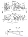
- La fig. 7 est une vue en plan représentant, à échelle différente, les éléments constitutifs d'une autre forme de réalisation de l'objet de l'invention.
- La fig. 8 est une vue prise selon la ligne VIII-VIII de la fig. 7.
- La fig. 9 est une élévation montrant l'association des éléments constitutifs sur une monture de lunettes.
- Fig. 1 is an elevation partly in section showing, in exploded form, the various constituent elements of the object of the invention.
- Fig. 2 is a plan view taken along line II-II of FIG. 1.
- Fig. 3 is an elevation illustrating a characteristic position of the constituent elements of the object of the invention, prior to its constitution.
- Figs. 4 and 5 illustrate two characteristic positions of the hinge according to the invention.
- Fig. 6 is a schematic side view of a spectacle frame showing the results arising from the positions of the hinge according to FIGS. 4 and 5.
- Fig. 7 is a plan view showing, on a different scale, the components of another embodiment of the subject of the invention.
- Fig. 8 is a view taken along line VIII-VIII of FIG. 7.
- Fig. 9 is an elevation showing the association of the constituent elements on a spectacle frame.
Les fig. 1 et 2 illustrent un exemple d'application d'une charnière conforme à l'invention entre une face 1 d'une monture de lunettes et une branche 2 latérale, par exemple droite. La charnière est du type comprenant deux parties complémentaires 3 et 4 rapportées respectivement sur la branche 2 et sur la face 1. La partie complémentaire 3 comprend une semelle 5 destinée à être fixée sur la branche 2 par des moyens d'immobilisation et de fixation 6, par exemple des vis ou des rivets. La semelle 5 forme en saillie, à partir de sa face 5a dite intérieure, un tenon 7 percé d'un trou 8 et susceptible d'être associé à deux encoches latérales en "V" 9 ménagées dans des épaulements 10.Figs. 1 and 2 illustrate an example of application of a hinge according to the invention between a
La seconde partie complémentaire 4 est prévue pour offrir deux charnons lla-llb percés de deux trous coaxiaux 12, en vue de l'association avec le tenon 7. Les trous 12 sont prévus pour le passage d'un axe de pivotement, non représenté, amené, après insertion du tenon 7 entre les charnons 11, à traverser également le trou 8. L'axe de pivotement peut être du type à lacet ou, au contraire, être constitué par une vis susceptible de coopérer avec un taraudage présenté par l'un des trous 12.The second
Selon l'invention, la seconde partie 4 constitutive de la charnière est constituée par deux pièces complémentaires 13 et 14 reliées entre elles pour former une articulation à un degré de liberté. L'axe de rotation des pièces 13 et 14 est orthogonal à l'axe de pivotement de la charnière proprement dit et l'amplitude de pivotement angulaire est limitée. Une telle articulation est complétée par un dispositif de réglage et d'immobilisation de l'orientation relative des pièces 13 et 14.According to the invention, the
La pièce 13 est constituée sous la forme d'une embase comportant, à partir d'une semelle 15, des moyens 15a de fixation avec la face 1. Dans l'exemple illustré, les moyens 15a sont constitués par une ou plusieurs griffes à redents, afin de permettre une insertion, injection ou introduction forcée dans la matière plastique constitutive de la face 1. Il est certain que d'autres moyens techniques équivalents peuvent être retenus pour constituer les moyens 15a. Par exemple, il peut être prévu de faire intervenir des pieds, des tenons, des axes, des rivets ou encore des vis, notamment en cas de monture métallique.The
L'embase 13 est prolongée à partir de la semelle 15 et à l'opposé des moyens m par une demi-croix 15a formant une portée semi-cylindrique 16, concentrique à un palier cylindrique 17, dont l'axe est contenu dans un plan P de symétrie de l'embase 13. La portée semi-cylindrique 16 est prolongée par un bossage saillant 18, de forme sensiblement semi-cylindrique, aligné avec le plan P et raccordé à la portée 16 par un pied 19 de plus faible section. Le diamètre du bossage 18 est inférieur à celui de la portée 16.The
La pièce complémentaire 13 est adaptée sur le côté intérieur de la face 1, à proximité du bord latéral droit, pour que l'axe du palier 17 soit sensiblement horizontal dans une position d'utilisation de la monture.The
La seconde pièce complémentaire 14 est constituée sous la forme d'une chape, comprenant une semelle 20 à partir de la face interne 20a de laquelle s'élèvet en saillie les charnons parallèles lla-llb. Ces derniers peuvent être réalisés de manière à présenter un contour polygonal présentant, notamment, deux angles saillants 21a et 21b, distants angulairement de, sensiblement, 90° et destinés à coopérer avec les encoches en "V" 9 de la partie 3.The second
La semelle 20 s'étend à l'opposé des charnons 11 et forme une plaquette 22 dont la largeur est au moins égale à la mesure correspondante de la semelle 5 de la pièce 13. La plaquette 22 présente, en son centre, un tourillon 23 de même diamètre que le palier 17. De préférence, la plaquette 22 possède, à l'opposé des charnons 11, un contour extérieur semi-circulaire concentrique au tourillon 23.The sole 20 extends opposite the knuckles 11 and forms a
Les charnons lla-llb forment, en direction de la plaquette 22, deux prolongements 24a-24b massifs, qui délimitent, à partir de leur face interne et de leur extrémité transversale correspondante, deux faces concaves de même enveloppe semi-cylindrique. Ces deux faces concentriques au tourillon 23 délimitent, ainsi, un siège 25 partiel semi-cylindrique. Les faces internes des prolongements 24 délimitent, également, à partir du siège 25, un évidement 26 d'enveloppe générale cylindrique, décalé latéralement par rapport au plan de symétrie longitudinal P' de la pièce 14. La fig. 2 montre que les prolongements 24a-24b possèdent, à partir de la semelle 20, une hauteur égale à la mesure axiale de la portée 16.The
Les prolongements 24a-24b présentent, par ailleurs, deux trous taraudés pratiqués selon une même direction parallèle aux trous 12 et au plan de la semelle 20. Les trous taraudés sont ménagés de manière à déboucher en opposition l'un de l'autre dans les faces des prolongements 24a-24b délimitant l'évidement 26. Les trous taraudés sont occupes par deux vis 28a-28b, de préférence sans tête, susceptibles d'être actionnées par un tournevis à partir des faces latérales extérieures des prolongements 24a-24b.The
La fig. 3 montre que, lors de l'assemblage, les pièces complémentaires 13 et 14 sont disposées en superposition de plans, de manière à rendre possible l'introduction du bossage 18 dans l'évidement 26 et du tourillon 23 dans le palier 17. Simultanément, la portée 16 est amenée en coopération avec le siège 25. Cette reconstitution de la partie 4 est effectuée après montage de la pièce 13 sur la face 1. La fig. 2 montre que cette face peut, le cas échéant, comporter un dégagement 30 ménagé dans son bord transversal pour permettre l'incrustation de la plaquette 22.Fig. 3 shows that, during assembly, the
Dans l'état illustré par la fig. 4, la pièce complémentaire 14 peut pivoter, relativement à l'embase 13, sur le tourillon 23, dans la mesure de débattement du bossage 18 à l'intérieur de l'évidement 26. A supposer que la vis 28b soit effacée par rapport à l'évidement 26, le vissage de la vis 28a établit un contact avec le bossage 18 qui est alors déplacé angulairement pour être appliqué sur la face concave du prolongement 24b définissant l'évidement 26.Dans. cette position, compte tenu du déport de-l'évidement 26 par rapport au plan P', la branche 2 s'étend de façon sensiblement perpendiculaire par rapport à la face 1, comme schématisé par.la fig. 6.In the state illustrated in fig. 4, the
Pour régler et ajuster l'angle facial devant être présenté par le plan de la face 1, la vis 28a est partiellement dévissée puis la vis 28b est vissée pour agir sur le bossage 18. Par réaction, la chappe 14 pivote dans le sens de la flèche f1, entraînant la branche 2 dans le sens correspondant (fig. 5). L'angle α maximal susceptible d'être atteint correspond au déport latéral conféré à l'évidement 26 par rapport au plan médian longitudinal P. Les caractéristiques du bossage 18, de l'évidement 26 et des vis 28a et 28b sont retenues, dans l'exemple illustré, pour que l'amplitude de pivotement possible soit voisine de 15".To adjust and adjust the facial angle to be presented by the plane of the
Les deux pièces 13 et 14 décrites ci-dessus peuvent être assemblées facilement dans une chaîne de fabrication automatique puisqu'il suffit d'un poste de travail de montage, pouvant être inséré à tout stade d'un cycle de travail et de montage automatique d'une monture de lunettes.The two
La coopération mutuelle du bossage 18, de l'évidement 26 et des vis 28a et 28b, réalise un dispositif de réglage et d'immobilisation de l'orientation requise de la branche 2. En effet, par exemple, la vis 28a peut être dévissée pour qu'en agissant sur la vis 28b, le réglage d'orientation précis puisse être apporté, Lorsque ce réglage est effectué, la vis 28b représente alors un organe de butée contre lequel est pressé le bossage 18 sollicité dans le sens correspondant par la vis 28a qui assume alors une fonction de blocage et d'immobilisation.The mutual cooperation of the
Les moyens mis en oeuvre offrent ainsi une possibilité de réglage simple, rapide et précis, pouvant être apporté par un personnel qualifié ou, éventuellement, directement par le sujet lui-même.The means used thus offer a possibility of simple, rapid and precise adjustment, which can be provided by qualified personnel or, possibly, directly by the subject himself.
Dans ce qui précède, il est indiqué que la charnière illustrée aux dessins est une charnière correspondant à une branche droite. Il va de soi-que la branche gauche d'une même monture est munie d'une charnière conforme à l'invention, de même conception, mais symétrique par rapport à un plan, c'est-à-dire possédant un évidement 26 déporté dans le sens correspondant pour former une charnière gauche.In the foregoing, it is indicated that the hinge illustrated in the drawings is a hinge corresponding to a straight branch. It goes without saying that the left arm of the same mount is provided with a hinge according to the invention, of the same design, but symmetrical with respect to a plane, that is to say having a recessed
Il y a lieu de noter que la liaison entre les pièces 13 et 14 est assurée par le tourillon 23 et la coopération entre la portée 16 et le siège 25. Il en résulte ainsi un centrage efficace de l'articulation qui présente une grande résistance mécanique aux sollicitations d'ouverture et de fermeture de la branche. Cette résistance est accrue par la coopération des vis 28a-28b et par la présence de la plaquette 22 qui représente aussi un cache dissimulant totalement la structure de l'embase 13.It should be noted that the connection between the
Bien que cela ne soit pas représenté, il est à considérer que les éléments constitutifs de liaison entre les pièces 13 et 14 peuvent faire intervenir l'inversion des moyens décrits pour ce qui concerne le tenon et les charnons ou encore la mise en oeuvre d'un nombre plus important de chacun de ces derniers.Although this is not shown, it is to be considered that the constituent connecting elements between the
Les fig. 7 à 9 illustrent une variante de réalisation selon laquelle la partie 4 est constituée par une pièce 131, conformée pour délimiter une encoche 31 d'emboîtement du cercle ou drageoir 32 d'une face de monture métallique. Dans un tel cas, la liaison est complétée de façon ferme et résistante, notamment par soudure.Figs. 7 to 9 illustrate an alternative embodiment according to which the
La pièce 131 est réalisée pour porter, à l'inverse de ce qui est décrit dans l'exemple ci-dessus, une plaquette 221, un siège 251, un évidement 261, un tourillon 231 et des vis 28a1 et 28b1 formant le dispositif d'immobilisation et d'orientation. Au contraire, la pièce 141 est conformée pour comporter des tenons 11a1 et 11b1, ainsi qu'un palier 161, une portée 171 et un bossage 181. The
Il y a lieu de noter, également, que dans cet exemple de réalisation, le dégagement 261 est centré par rapport au plan de symétrie longitudinal P'. De cette façon, les moyens de l'invention permettent un débattement angulaire possible de.même amplitude de la branche 2, de part et d'autre dudit plan, selon un angle α global, par exemple égal à 10°.It should also be noted that in this exemplary embodiment, the
L'invention n'est pas limitée aux exemples décrits et représentés car diverses modifications peuvent y être apportées sans sortir de son cadre.The invention is not limited to the examples described and shown since various modifications can be made without departing from its scope.
Claims (8)
Applications Claiming Priority (2)
| Application Number | Priority Date | Filing Date | Title |
|---|---|---|---|
| FR8111447A FR2507334A1 (en) | 1981-06-03 | 1981-06-03 | HINGE FOR EYEWEAR MOUNT |
| FR8111447 | 1981-06-03 |
Publications (2)
| Publication Number | Publication Date |
|---|---|
| EP0067110A2 true EP0067110A2 (en) | 1982-12-15 |
| EP0067110A3 EP0067110A3 (en) | 1983-06-15 |
Family
ID=9259366
Family Applications (1)
| Application Number | Title | Priority Date | Filing Date |
|---|---|---|---|
| EP82420070A Withdrawn EP0067110A3 (en) | 1981-06-03 | 1982-06-02 | Spectacle frame hinges |
Country Status (2)
| Country | Link |
|---|---|
| EP (1) | EP0067110A3 (en) |
| FR (1) | FR2507334A1 (en) |
Cited By (11)
| Publication number | Priority date | Publication date | Assignee | Title |
|---|---|---|---|---|
| GB2181569A (en) * | 1985-10-02 | 1987-04-23 | Neil Brosgill | Improvements relating to spectacle frames and their manufacture |
| FR2679047A1 (en) * | 1991-07-11 | 1993-01-15 | Jullien Lunetterie Henry | Hinge for a spectacles frame |
| EP0654691A1 (en) * | 1993-11-19 | 1995-05-24 | Heinrich Uphoff | Spectacle frame |
| EP0656557A1 (en) * | 1993-12-03 | 1995-06-07 | KILLER LOOP S.p.A. | Hinge for eyeglasses |
| FR2714492A1 (en) * | 1993-12-28 | 1995-06-30 | Alcad | Adjustable pivoted arm for spectacle frame |
| FR2724466A1 (en) * | 1994-09-08 | 1996-03-15 | Bolle Ets | Detachable hinge for arm of spectacles |
| FR2725046A1 (en) * | 1994-09-22 | 1996-03-29 | Jullien Henry Lunetterie Sa | Adjustable elastic hinge for arm of spectacle frame |
| WO1996031798A1 (en) * | 1995-04-07 | 1996-10-10 | Heinrich Uphoff | Glasses frame |
| FR2737020A1 (en) * | 1995-07-21 | 1997-01-24 | Chevassus | Spectacle frame with double elastic hinge mechanism - has arms with elastically-biassed vertical-axis first hinges connected to one part of horizontal-axis second hinges attached to frame front |
| EP1061400A1 (en) * | 1999-06-17 | 2000-12-20 | Heinrich Uphoff | Spectacle frame |
| WO2021167932A1 (en) * | 2020-02-18 | 2021-08-26 | Magic Leap, Inc. | Multiple degree of freedom hinge systems and eyewear devices comprising such hinge systems |
Citations (2)
| Publication number | Priority date | Publication date | Assignee | Title |
|---|---|---|---|---|
| FR1552667A (en) * | 1967-02-11 | 1969-01-03 | ||
| DE1286780B (en) * | 1965-11-02 | 1969-01-09 | Winter Optik | Glasses, especially work glasses, with an inclination joint |
-
1981
- 1981-06-03 FR FR8111447A patent/FR2507334A1/en active Granted
-
1982
- 1982-06-02 EP EP82420070A patent/EP0067110A3/en not_active Withdrawn
Patent Citations (2)
| Publication number | Priority date | Publication date | Assignee | Title |
|---|---|---|---|---|
| DE1286780B (en) * | 1965-11-02 | 1969-01-09 | Winter Optik | Glasses, especially work glasses, with an inclination joint |
| FR1552667A (en) * | 1967-02-11 | 1969-01-03 |
Cited By (14)
| Publication number | Priority date | Publication date | Assignee | Title |
|---|---|---|---|---|
| GB2181569A (en) * | 1985-10-02 | 1987-04-23 | Neil Brosgill | Improvements relating to spectacle frames and their manufacture |
| FR2679047A1 (en) * | 1991-07-11 | 1993-01-15 | Jullien Lunetterie Henry | Hinge for a spectacles frame |
| EP0654691A1 (en) * | 1993-11-19 | 1995-05-24 | Heinrich Uphoff | Spectacle frame |
| US5596789A (en) * | 1993-12-03 | 1997-01-28 | Killer Loop S.P.A. | Hinge for eyeglasses |
| EP0656557A1 (en) * | 1993-12-03 | 1995-06-07 | KILLER LOOP S.p.A. | Hinge for eyeglasses |
| FR2714492A1 (en) * | 1993-12-28 | 1995-06-30 | Alcad | Adjustable pivoted arm for spectacle frame |
| FR2724466A1 (en) * | 1994-09-08 | 1996-03-15 | Bolle Ets | Detachable hinge for arm of spectacles |
| US5646708A (en) * | 1994-09-08 | 1997-07-08 | Establissements Bolle | Coupling system for assembling a spectacle frame and the side-pieces |
| FR2725046A1 (en) * | 1994-09-22 | 1996-03-29 | Jullien Henry Lunetterie Sa | Adjustable elastic hinge for arm of spectacle frame |
| WO1996031798A1 (en) * | 1995-04-07 | 1996-10-10 | Heinrich Uphoff | Glasses frame |
| FR2737020A1 (en) * | 1995-07-21 | 1997-01-24 | Chevassus | Spectacle frame with double elastic hinge mechanism - has arms with elastically-biassed vertical-axis first hinges connected to one part of horizontal-axis second hinges attached to frame front |
| EP1061400A1 (en) * | 1999-06-17 | 2000-12-20 | Heinrich Uphoff | Spectacle frame |
| WO2021167932A1 (en) * | 2020-02-18 | 2021-08-26 | Magic Leap, Inc. | Multiple degree of freedom hinge systems and eyewear devices comprising such hinge systems |
| US11726347B2 (en) | 2020-02-18 | 2023-08-15 | Magic Leap, Inc. | Multiple degree of freedom hinge systems and eyewear devices comprising such hinge systems |
Also Published As
| Publication number | Publication date |
|---|---|
| EP0067110A3 (en) | 1983-06-15 |
| FR2507334A1 (en) | 1982-12-10 |
| FR2507334B1 (en) | 1985-03-29 |
Similar Documents
| Publication | Publication Date | Title |
|---|---|---|
| EP2404211B1 (en) | Frame for spectacles with telescopic hinges, and hinge for the frame | |
| EP0067110A2 (en) | Spectacle frame hinges | |
| FR2836039A1 (en) | GLENOIDAL COMPONENT OF SHOULDER PROSTHESIS AND TOTAL SHOULDER PROSTHESIS INCORPORATING SUCH COMPONENT | |
| FR2796471A1 (en) | HIGH FLEXIBILITY ELASTIC HINGE | |
| CH635444A5 (en) | GLASSES HINGE. | |
| FR3062927A1 (en) | GLASSES ORIENTATION OF THE BRANCHES ACCORDING TO SEVERAL PLANS | |
| EP1136010B1 (en) | Articulated bracelet, particularly for watches | |
| EP1301819B1 (en) | Spectacles with wire-like branches | |
| FR2795529A1 (en) | Spectacle frame and side-piece hinge has spring strip on side piece lying parallel to axis of rotation and pressing against lug surface | |
| FR2486252A1 (en) | Spectacle frame with sprung legs - has spring strip acting on cam shape to hold legs in open or closed position | |
| EP1403682B1 (en) | Rimless spectacles | |
| EP0141767A2 (en) | Set of a nose pad and nose pad support for spectacles | |
| FR2770653A1 (en) | Spectacle frame and side piece connector | |
| WO2008029024A2 (en) | Hinge or joint for spectacles with adjustable closing angle | |
| FR2562275A1 (en) | Device for the cosmetic treatment of one eye and/or of the zone which surrounds it while correcting the vision of the other | |
| FR3049726A1 (en) | JOINT FRAME JOINT | |
| CA3168964A1 (en) | Temple for a pair of eyeglasses | |
| EP2773997B1 (en) | Spectacle frame having rotating arms | |
| CH402449A (en) | Eyeglass frame hinge | |
| FR2982040A1 (en) | PIVOTING BRANCH FOR EYEWEAR MOUNT | |
| FR2787891A1 (en) | Spring-loaded hinge for spectacle frame side-piece has spring operating exclusively by flexion and in one direction only | |
| FR2803920A1 (en) | Hinge for spectacle frame has curved rod on arm of spectacles forming pivot pin for bracket | |
| FR2880140A1 (en) | Spectacles` joint for assembling front and temple of spectacles, has ball joints for front and temple, respectively, and space between ball joints for permitting inclination of front, where one ball joint permits rotation of front | |
| EP3625619A1 (en) | Spectacle frame having temples with a modifiable curvature and with extended opening | |
| FR3115892A1 (en) | Spectacle frame holder. |
Legal Events
| Date | Code | Title | Description |
|---|---|---|---|
| PUAI | Public reference made under article 153(3) epc to a published international application that has entered the european phase |
Free format text: ORIGINAL CODE: 0009012 |
|
| AK | Designated contracting states |
Designated state(s): AT CH DE IT LI |
|
| PUAL | Search report despatched |
Free format text: ORIGINAL CODE: 0009013 |
|
| AK | Designated contracting states |
Designated state(s): AT CH DE IT LI |
|
| 17P | Request for examination filed |
Effective date: 19830510 |
|
| STAA | Information on the status of an ep patent application or granted ep patent |
Free format text: STATUS: THE APPLICATION IS DEEMED TO BE WITHDRAWN |
|
| 18D | Application deemed to be withdrawn |
Effective date: 19850108 |
|
| RIN1 | Information on inventor provided before grant (corrected) |
Inventor name: CHEVASSUS, PIERRE |