EP0066945A2 - Systèmes de commande pour mono-embrayage de transmissions à demi-arbres - Google Patents
Systèmes de commande pour mono-embrayage de transmissions à demi-arbres Download PDFInfo
- Publication number
- EP0066945A2 EP0066945A2 EP82302028A EP82302028A EP0066945A2 EP 0066945 A2 EP0066945 A2 EP 0066945A2 EP 82302028 A EP82302028 A EP 82302028A EP 82302028 A EP82302028 A EP 82302028A EP 0066945 A2 EP0066945 A2 EP 0066945A2
- Authority
- EP
- European Patent Office
- Prior art keywords
- transfer case
- clutch
- control system
- wheel drive
- way valve
- Prior art date
- Legal status (The legal status is an assumption and is not a legal conclusion. Google has not performed a legal analysis and makes no representation as to the accuracy of the status listed.)
- Granted
Links
Images

Classifications
-
- B—PERFORMING OPERATIONS; TRANSPORTING
- B60—VEHICLES IN GENERAL
- B60K—ARRANGEMENT OR MOUNTING OF PROPULSION UNITS OR OF TRANSMISSIONS IN VEHICLES; ARRANGEMENT OR MOUNTING OF PLURAL DIVERSE PRIME-MOVERS IN VEHICLES; AUXILIARY DRIVES FOR VEHICLES; INSTRUMENTATION OR DASHBOARDS FOR VEHICLES; ARRANGEMENTS IN CONNECTION WITH COOLING, AIR INTAKE, GAS EXHAUST OR FUEL SUPPLY OF PROPULSION UNITS IN VEHICLES
- B60K23/00—Arrangement or mounting of control devices for vehicle transmissions, or parts thereof, not otherwise provided for
- B60K23/08—Arrangement or mounting of control devices for vehicle transmissions, or parts thereof, not otherwise provided for for changing number of driven wheels, for switching from driving one axle to driving two or more axles
Definitions
- This invention relates to control systems for operating the clutch of single-clutch split axle drive mechanisms as used in part-time four-wheel drive vehicles.
- a common drive configuration for a part-time four-wheel drive vehicle comprises a transfer case having an input shaft driven by the vehicle transmission, and two output shafts.
- One output shaft is drive-connected to the input shaft for continuously driving one set of vehicle wheels, usually the rear wheels, through a propeller shaft, differential and split axle.
- the second output shaft constitutes an auxiliary output shaft, and is connectible to the input shaft by a clutch or comparable mechanism in the transfer case for selectively driving the other set of vehicle wheels, usually the front wheels, through a second propeller shaft, differential and split axle.
- Two-wheel drive is provided when the clutch in the transfer case is disengaged, and four-wheel drive is provided when the clutch is engaged.
- a long-standing problem associated with part-time four-wheel drive configurations of the above type is wear and power consumption in the two-wheel drive mode. This is caused by the non-driven front wheels back-driving the drive line components between the non-driven wheels and the clutch or comparable mechanism in the transfer case which disconnects the second output shaft from the transfer case input shaft.
- a known solution to reducing wear and power consumption is the use of a single clutch in the axle assembly for the selectively driven wheels which disconnects one of the selectively driven wheels from its associated side gear in the differential when the vehicle is in the two-wheel drive mode.
- Such a construction is disclosed in the specification of European patent application no. 81300460.3 (0035324).
- the present invention is concerned with a control system for automatically operating the clutch of a single-clutch split axle drive mechanism responsive to the operational mode of a transfer case with which the split axle drive mechanism is used in a part-time four-wheel drive vehicle powered by an internal combustion engine, and is characterised in that the control system comprises a vacuum motor mechanically connected to the clutch so that the clutch is biased towards a position of disengagement when the vacuum motor is vented and is biased towards a position of engagement when the vacuum motor is evacuated, conduit means connecting the vacuum motor to a vacuum source provided by the internal combustion engine, a two-way valve interposed in the conduit means and having a first operative position in which the vacuum motor is connected to a vent and a second operative position in which the vacuum motor is connected to the vacuum source for evacuating the vacuum motor, means effective to position the two-way valve in its second operative position when the transfer case is in a four-wheel drive mode, whereby the clutch is automatically engaged when four-wheel drive is selected, and means effective to mechanically position the two-way valve in
- control system in accordance with the invention can make use to a significant extent of components already on the vehicle, thereby reducing the number of additional components required by the system.
- control system does not require any power to disengage the clutch, the control system contributes to fuel economy in the two-wheel drive mode.
- the clutch fork can be operated directly by the vacuum motor without the necessity of a complicated shifter mechanism.
- the control system may incorporate a time delay effective between the shift to four-wheel drive in the transfer case and the application of clutch-engage forces in the split axle drive mechanism, so that four-wheel drive can be selected whilst the vehicle is in motion.
- the control system may include a vacuum check valve so that the system can operate off the engine intake manifold.
- the control system may be electrically activated and de-activated, and this can be effected by a switch associated with the transfer case. This offers the possibility of the control system using the engine intake manifold as a vacuum source, and also using a pre-existing switch associated with the transfer case to activate and de-activate the system, thereby reducing the number of additional components required by the system.
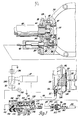
- Figure 1 shows a schematic plan view of a part-time four-wheel drive vehicle, comprising an internal combustion engine 10, transmission 12 and transfer case 14 mounted on a vehicle chassis (not shown).
- the engine 10 and transmission 12 are well-known components, as is the transfer case 14, which typically has an input shaft (not shown), a main output shaft 16 and an auxiliary output shaft 18.
- the main output shaft 16 is drive-connected to the input shaft in the transfer case 14 and is customarily aligned with it.
- the auxiliary output shaft 18 is drive-connectible to the input shaft by a clutch or comparable mechanism in the transfer case 14 and customarily off-set from it.
- the transfer case clutch is actuated by a selector mechanism (not shown), which in this embodiment is remotely controlled by the vehicle driver.
- the main output shaft 16 is drivingly connected to a rear propeller shaft 20, which in turn is drivingly connected to a rear differential 22.
- the rear differential 22 drives the rear wheels 24 by way of split axle parts in well-known manner.
- the auxiliary output shaft 18 is drivingly connected to a front propeller shaft 26 which in turn is drivingly connected to a split axle drive mechanism 28 for selectively driving the front wheels 30 by way of split axle parts.
- the split axle drive mechanism 28 is shown as including an automotive type differential 32 inside a housing 34.
- the differential 32 has a drive shaft 36 and a differential case 38 rotatably mounted in the housing 34 on orthogonally related axes.
- the drive shaft 36 is the differential input and has an external yoke 40 at one end for universally coupling the drive shaft 36 to the front propeller shaft 26.
- the internal end of the drive shaft 36 has an integral drivingpinion 42 which meshes with a ring gear 44 attached to the differential case 38.
- the differential case 38 carries a plurality of rotatable pinion gears 46 mounted on a cross pin 48.
- the pinion gears 46 mesh with side gears 50 and 52 which are splined to the ends of the stub shafts 54 and 56 respectively.
- the stub shafts 54 and 56 are rotatably mounted in the housing 34 on the differential case axis. These stub shafts are rotatable relative to each other and to the differential case.
- the differential 32 as thus far described, and its mode of operation, are well-known.
- the split drive axle mechanism 28 further includes a single positive clutch 58 which changes the mode of operation of the differential 32 and makes the mechanism particularly useful for the control of selectively driven wheels in a part-time four-wheel drive vehicle.
- the clutch 58 comprises an integral spline wheel 60 at the outer end of the stub shaft 54 and a matching spline wheel 62 attached to the inner end of an extension shaft 64.
- the extension shaft 64 has its inner end journalled in the hollow outer end of the stub shaft 54 and its outer end journalled in a bearing (not shown) at the remote end of an extension tube 66 attached to the housing 34.
- the clutch 58 further includes an internally splined sleeve 68 which is slidably mounted on the spline wheel 60.
- the internally splined sleeve 68 is shiftable between a disengaged position (shown in solid lines in Figures 2 and 3) and an engaged position (shown in phantom lines in Figure 3) where it couples together the spline wheels 60 and 62.
- the split axle drive mechanism 28 is attached to the vehicle chassis by means of a housing bracket (not shown) and a bracket 70 on the extension tube 66.
- the split axle drive mechanism 28 has two outputs for the respective split axle parts associated with the respective front wheels 30.
- One output is the stub shaft 54, clutch 58 and extension shaft 64 which has an external flange 72 for attachment of one of the split axle parts.
- the other output is the stub shaft 56 which has an external flange 74 for attachment of the other split axle part.
- Suitable split axle parts are well-known from front wheel drive automobiles. These may be used for connecting the split axle drive mechanism 28 to the front wheels 30.
- the drawings schematically illustrate a common type of half shaft for driving connection to independently suspended steerable vehicle wheels, comprising an axle shaft 76 having a plunging universal joint 78 at its inboard end adapted for connection to an output such as the flange 72 or 74, and the well-known Rzeppa-type universal joint 80 at its outboard end adapted to be connected to the vehicle wheel 30.
- the split axle drive mechanism 28 also includes a shifter 81 for operating the clutch 58.
- the shifter 81 as shown in Figure 3, comprises a fork 82 having its tines engaged in an external groove of the slee.ve.58 and its base slidably mounted on a slide 84.
- the fork 82 is positioned on the slide 84 by opposed coil springs 86 and 88.
- the slide 84 is itself arranged for translational movement by a push-pull cable 90.
- Figure 3 shows in solid lines the fork 82 and the slide 84 in the clutch-disengaged position.
- the clutch 58 is engaged by moving the slide 84 to the left from the solid-line position shown in Figure 3: this loads the spring 88, which in turn biases the fork 82 and sleeve 68 towards the left.
- the sleeve 68 then slides into engagement with the spline wheel 62 under the action of the spring 88 when their respective splines align in a complementary manner.
- the clutch 58 is disengaged by returning the slide 84 to the position shown in Figure 3. This loads the spring 86, which in turn returns the slide 84 and fork 82 to the clutch-disengaged position when the biasing force of the spring 86 is sufficient to overcome the torque load on the engaged splines of the spline wheel 62 and sleeve 68.
- a control system for operating the clutch 58 via the push-pull cable 90 and shifter 81 is shown in the lower portion of Figure 3.
- the control system comprises a vacuum motor 92, a solenoid operated two-way slide valve 94, a vacuum check valve 96, three rubber conduits or hoses 98, 100 and 102, and an orifice device 103.
- the vacuum motor 92 comprises a hard plastics cup-shaped shell 104 and a flexible cup-shaped diaphragm 106 attached together rim-to-rim to form a collapsible chamber 108.
- the bottom wall of the diaphragm 106 is reinforced by plates 110 and 112 which are on opposite sides of the bottom wall and riveted together.
- the diaphragm 106 is normally extended as shown in Figure 3: it is biased into this extended position by a coil spring 114 inside the chamber 108.
- the hard plastics shell 104 has a nipple 116 which forms a port 117 for either evacuating or venting the chamber 108.
- the push-pull cable 90 which operates the shifter 81 for the clutch 58 is attached to an eyelet of the outer plate 112, as shown in Figure 3, so that the clutch 58 is disengaged when the chamber 108 is vented to atmosphere and the diaphragm 106 of the vacuum motor 92 is extended.
- the vacuum motor 92 is mounted on a U-shaped bracket 118 which in turn is fixedly mounted in the engine compartment of the vehicle, such as by fastening the bracket 118 to a body panel as schematically represented in Figure 1.
- the two-way slide valve 94 can also be conveniently mounted on the bracket 118 as shown in Figure 1. However, the slide valve 94 is shown in a detached position in Figure 3 for clarity.
- the two-way slide valve 94 comprises a sheet metal cup 119 with a plastics spool secured in it to provide a cylindrical valve chamber 120.
- the valve chamber 120 has coaxial ports 122, 124 at opposite ends, and a radial port 126.
- the ports 122 and 124 are vent and vacuum ports, respectively.
- the orifice device 103 is a bias cup having a small hole through its bottom wall. The cup is mounted in the outer end of the radial port 126, and the radial port 126 is connected to the vacuum motor 92 by the rubber hose 98.
- a slide member 128 is disposed in the valve chamber 120.
- the slide member 128 has stems 130, 132 at its opposite ends which co-operate with the respective vent and vacuum ports 122 and 124.
- the slide member 128 is biased by a coil spring 134 to an extended position in which the stem 132 closes the vacuum port 124 as shown in Figure 3. Consequently, the vacuum motor 92 is normally vented via the open vent port 122.
- the valve chamber 120 is surrounded by a solenoid coil 136 which, when energized, retracts the slide member 128 so that the stem 130 closes the vent port 122 and the vacuum port 124 is opened.
- An enlarged centre section 129 of the slide member 128 is a cylinder with four equally spaced flats 131. The cylinder pilots the slide member 128 in the valve chamber 120, and the flats 131 permit flow from one end of the valve chamber 120 to the other, particularly in the vent mode illustrated in Figure 3, in which air at atmospheric pressure flows from the vent port 122 to the vacuum motor 92 via the radial port 126.
- the vacuum port 124 is connected to the vacuum check valve 96 by the rubber hose 100.
- the vacuum check valve 96 comprises a plastics housing 137 having a nipple at each end to form respective suction and discharge ports 138, 139 for a valve chamber 140.
- the suction port 138 is connected to the vacuum port 124 of the slide valve 94 by the hose 100 as indicated above.
- the discharge port 139 is connected by the hose 102 to a vacuum source, such as the intake manifold of the internal combustion engine 10.
- the valve chamber 137 has an internal apertured wall 141 which supports a coil spring 143 and a flat plug 142 which is biased by the coil spring to block the suction port 138.
- the vacuum check valve 96 permits air flow from the slide valve 94 to the vacuum source that is, in the direction of the arrow 144 shown in Figure 3, but prevents air flow from the vacuum source to the slide valve 94.
- the vacuum check valve 96 prevents the engine from bleeding down the vacuum motor 92 when the chamber 108 is evacuated.
- the solenoid-operated two-way slide valve 94 has a plastics socket 146 at the end which has the vent port 122.
- the socket 146 houses a pair of male blade terminals 148, 150 attached to the respective ends of the solenoid coil 136.
- the socket 146 also houses a filter 152 for the vent port 122.
- transfer cases for part-time four-wheel drive vehicles commonly include an electric swtich which is closed when the transfer case is in the four-wheel drive mode.
- the closed switch completes a circuit to an indicator light on the vehicle instrument panel to advise the vehicle driver that the vehicle is in the four-wheel drive mode, as is disclosed for instance in U.S. Patent 3,283,298 (Kaiser) issued November 1, 1966.
- Figure 3 schematically illustrates a transfer case 14 having a switch 154.
- the switch 154 is operatively connected to the transfer case 14 so that the switch 154 opens when the transfer case 14 is in the two-wheel drive mode and closes when the transfer case 14 is in the four-wheel drive mode.
- the switch 154 is electrically connected in series with the vehicle battery 156 and two branch circuits, one of which has an indicator light 158 and the other of which includes the solenoid coil 136. Consequently, the solenoid coil 136 is also energized when the indicator light 158 is lit in response to the transfer case 14 being in the four-wheel drive mode.
- the two-wheel drive mode of operation is illustrated in Figures 2 and 3.
- the drive to the auxiliary output shaft 18 is disconnected in the transfer case, and consequently the switch 154 is open.
- the slide member 128 is extended under the action of the spring 134, in a position blocking the vacuum port 124 and opening the vent port 122.
- the clutch 58 is disengaged and is held in the disengaged position by the coil spring 114 in the vacuum motor 92 acting on the shifter 81 via the push-pull cable 90.
- control system does not require any power for operation in the two-wheel drive mode, since the vacuum motor 92 is vented and the solenoid-operated two-way slide valve 94 is de-energized. Consequently, the control system itself enchances fuel economy in the two-wheel drive mode.
- the auxiliary output shaft 18 is drive-connected to the input shaft in the transfer case 14 and the switch 154 is closed, setting off two chains of events which result in the clutch 56 automatically being engaged.
- the transfer case output shaft 18 now drives the drive shaft 36 (differential input) and the differential case 38.
- the driven or rotating differential case 38 in turn reverses the direction of rotation of the counter-rotating side gear 50 so that the side gear 50 and stub shaft 54 rotate in the same direction as the side gear 52 and the extension shaft 64, which are driven by the respective front vehicle wheels 30.
- the driven differential case 38 tends to synchronize the speeds of the stub shaft 54 and the extension shaft 64.
- the closed switch 154 produces energization of the solenoid coil 136 of the two-way slide valve 94, so retracting the slide member 128.
- the retracted slide member 128 closes the vent port 122, and opens the vacuum port 124, which connects the chamber 108 of the vacuum motor 92 to the vacuum source provided by the internal combustion engine 10 by way of the hose 102, vacuum check valve 96, hose 100, vacuum port 124, radial port 126, orifice device 103, rubber hose 98 and port 117.
- the vacuum chamber 108 is thereby evacuated, so producing a clutch, engage force which collapses the diaphragm 106 against the action of the spring 114 and acts via the cable 90 to pull the slide 84 to the left from the solid-line position shown in Figure 3. Movement of the slide 84 loads the coil spring 88, which biases the shifter fork 82 and sleeve 68 towards the clutch-engage position. The sleeve 68 then slides into engagement with the spline wheel 62 under the action of the spring 88 when their respective splines align in a complementary manner.
- both front wheels 30 are driven, and the split axle drive mechanism 28 acts as a conventional differential.
- the orifice device 103 provides a time delay of approximately two to three seconds between the time that the switch 154 is closed and the vacuum chamber 108 is evacuated. This time delay is provided so that the direction of rotation of the counter-rotating side gear 50 is reversed and the sleeve 68 is rotating in the same direction as the spline wheel 62 before any substantial clutch-engage force is produced by the vacuum motor 92. This time delay feature permits the vehicle operator to shift the transfer case 14 from two-wheel drive to four-wheel drive while the vehicle is in motion.
- Another feature is the vacuum check valve 96 which keeps the chamber 108 evacuated once it has been evacuated by the engine intake manifold. This feature prevents the evacuated chamber 108 from being bled down by a low vacuum in the engine intake manifold such as during a steep hill climb in four-wheel drive.
- the clutch 56 is also automatically disengaged when the vehicle is returned to the two-wheel drive mode.
- the switch 154 opens, so de-energizing the solenoid coil 136.
- the slide member 128 is then biased by the spring 134 to the position shown in Figure 3, in which the vacuum port 124 is closed and the vent port 122 is open .
- the chamber 108 is thereby vented, and the diaphgram 106 extends, assisted by the bias of the coil spring 114. This movement in turn pushes the slide 84 via the push-pull cable 90 to the clutch-disengaged position shown in Figure 3, so loading the coil spring 86.
- the coil spring 86 then biases the fork 82 and sleeve 68 towards the solid-line position shown in Figure 3.
- the clutch 58 automatically disengages when the force of the spring 86 becomes sufficient to overcome the torque loading between the spline wheel 62 and the sleeve 68, which usually occurs on slight deceleration of the vehicle.
- the clutch 58 is disengaged, there is no back drive to the differential case 38, as indicated earlier.
- the shifter 81 provides a redundancy when used in conjunciton with the control system illustrated in Figure 3.
- the coil springs 86 and 88 bias the sleeve 68 towards the disengaged and engaged positions respectively, so that the clutch 58 is not engaged and disengaged with excessive force, which could happen if the shift fork 82 were operated by a solid mechanical linkage.
- the vacuum motor 92 itself provides controlled clutch engagement and disengagement forces, it is possible to simplify the shifter 81 by.eliminating the springs 86 and 88 and fixing the shift fork 82 on the slide 84 so that the push-pull cable 90 moves the shift fork 82 directly.
Landscapes
- Engineering & Computer Science (AREA)
- Chemical & Material Sciences (AREA)
- Combustion & Propulsion (AREA)
- Transportation (AREA)
- Mechanical Engineering (AREA)
- Arrangement And Mounting Of Devices That Control Transmission Of Motive Force (AREA)
- Arrangement Or Mounting Of Control Devices For Change-Speed Gearing (AREA)
- Arrangement And Driving Of Transmission Devices (AREA)
- Hydraulic Clutches, Magnetic Clutches, Fluid Clutches, And Fluid Joints (AREA)
Applications Claiming Priority (2)
| Application Number | Priority Date | Filing Date | Title |
|---|---|---|---|
| US06/268,580 US4407387A (en) | 1981-05-29 | 1981-05-29 | Control system for split axle drive mechanism |
| US268580 | 1988-11-08 |
Publications (3)
| Publication Number | Publication Date |
|---|---|
| EP0066945A2 true EP0066945A2 (fr) | 1982-12-15 |
| EP0066945A3 EP0066945A3 (en) | 1985-04-03 |
| EP0066945B1 EP0066945B1 (fr) | 1987-04-08 |
Family
ID=23023611
Family Applications (1)
| Application Number | Title | Priority Date | Filing Date |
|---|---|---|---|
| EP82302028A Expired EP0066945B1 (fr) | 1981-05-29 | 1982-04-20 | Systèmes de commande pour mono-embrayage de transmissions à demi-arbres |
Country Status (5)
| Country | Link |
|---|---|
| US (1) | US4407387A (fr) |
| EP (1) | EP0066945B1 (fr) |
| JP (1) | JPS57204329A (fr) |
| CA (1) | CA1191458A (fr) |
| DE (1) | DE3275988D1 (fr) |
Cited By (4)
| Publication number | Priority date | Publication date | Assignee | Title |
|---|---|---|---|---|
| EP0204665A1 (fr) * | 1985-05-29 | 1986-12-10 | FIAT AUTO S.p.A. | Transmission intégrale pour véhicules à moteurs comprenant un dispositif d'embrayage de l'essieu secondaire |
| WO1994013505A1 (fr) * | 1992-12-09 | 1994-06-23 | AKTSIONERNOE OBSCHESTVO ZAKRYTOGO TIPA 'AvtoVAZ-Sher' | Dispositif de fixation du train reducteur d'un entrainement de roues |
| GB2318774A (en) * | 1996-10-30 | 1998-05-06 | Suzuki Motor Co | Two/four wheel drive shifting device |
| EP2116411B1 (fr) | 2008-05-06 | 2018-08-22 | GKN Automotive Limited | Chaîne cinématique pour une véhicule automobile doté d'un axe secondaire commutable |
Families Citing this family (42)
| Publication number | Priority date | Publication date | Assignee | Title |
|---|---|---|---|---|
| JPS58133922A (ja) * | 1982-01-29 | 1983-08-09 | Fuji Heavy Ind Ltd | 4輪駆動車の切換制御装置 |
| JPS59109430A (ja) * | 1982-12-15 | 1984-06-25 | Fuji Heavy Ind Ltd | パ−トタイム式4輪駆動車の切換制御装置 |
| JPS59109431A (ja) * | 1982-12-16 | 1984-06-25 | Fuji Heavy Ind Ltd | 4輪駆動車の切換制御装置 |
| JPS60226326A (ja) * | 1984-04-23 | 1985-11-11 | Daihatsu Motor Co Ltd | 4輪駆動車 |
| US4625584A (en) * | 1984-11-05 | 1986-12-02 | Toyota Jidosha Kabushiki Kaisha | Split axle drive mechanism for part-time four-wheel drive vehicle |
| JPS61119424A (ja) * | 1984-11-15 | 1986-06-06 | Daihatsu Motor Co Ltd | 4輪駆動車 |
| JPS61119426A (ja) * | 1984-11-15 | 1986-06-06 | Daihatsu Motor Co Ltd | 4輪駆動車 |
| US4592442A (en) * | 1984-11-29 | 1986-06-03 | International Harvester Company | Control system for a vehicle with two speed rear axle and single speed front axle drive |
| CN85101984B (zh) * | 1985-04-01 | 1988-01-27 | 第二汽车制造厂 | 复合式自锁差速系统 |
| US4627512A (en) * | 1985-04-12 | 1986-12-09 | Warn Industries, Inc. | Air actuated clutch for four wheel drive vehicles |
| JPH056180Y2 (fr) * | 1986-03-03 | 1993-02-17 | ||
| US4699235A (en) * | 1986-03-24 | 1987-10-13 | General Motors Corporation | Linear actuator control system for split axle drive mechanism |
| JPS62244716A (ja) * | 1986-04-17 | 1987-10-26 | Toyota Motor Corp | 四輪駆動車の制御方法 |
| US5044479A (en) * | 1990-03-12 | 1991-09-03 | Boulder 12 Investments | Remote-activated, power shift clutch assembly |
| US5123513A (en) * | 1990-03-12 | 1992-06-23 | Boulder 12 Investments | Remote-activated, power shift clutch assembly with positive locking |
| US5429221A (en) * | 1993-06-07 | 1995-07-04 | Ford Motor Company | All-wheel drive free-wheel mechanism for a motor vehicle |
| US5605213A (en) * | 1994-12-21 | 1997-02-25 | White; Richard E. | Instant actuator for split axle drive mechanism |
| US5967279A (en) * | 1995-08-28 | 1999-10-19 | Ntn Corporation | Hub clutch assembly |
| US6234289B1 (en) | 1996-05-22 | 2001-05-22 | Warn Industries, Inc. | Pneumatic annular actuator |
| US5806371A (en) * | 1996-07-23 | 1998-09-15 | American Axle & Manufacturing, Inc. | Gear arrangement with backlash adjustment |
| US5950750A (en) * | 1997-09-16 | 1999-09-14 | Chrysler Corporation | Drive arrangement for a motor vehicle |
| US6076420A (en) * | 1997-09-30 | 2000-06-20 | Ntn Corporation | Power transmission changeover devices for four-wheel drive vehicles |
| US6588559B2 (en) | 2001-09-18 | 2003-07-08 | Borgwarner, Inc. | Two-way clutch biasing assembly |
| US6814200B2 (en) | 2002-07-23 | 2004-11-09 | Borgwarner, Inc. | Clutch assembly having anti-skew engagement mechanism |
| US6719109B1 (en) | 2002-09-30 | 2004-04-13 | Borgwarner Inc. | Method for controlling a bi-directional clutch |
| US6832674B2 (en) * | 2002-12-05 | 2004-12-21 | Borgwarner, Inc. | Bi-directional four-mode clutch |
| US6830142B2 (en) * | 2002-12-19 | 2004-12-14 | Borgwarner, Inc. | Power splitting transfer cases for changing vehicle traction drives |
| US6745880B1 (en) | 2003-02-03 | 2004-06-08 | Borgwarner, Inc. | Two-way clutch assembly having selective actuation |
| US6814201B2 (en) * | 2003-02-13 | 2004-11-09 | Borgwarner, Inc. | Bi-directional axially applied pawl clutch assembly |
| US6905009B2 (en) * | 2003-05-30 | 2005-06-14 | Borgwarner, Inc. | Bi-directional clutch having a momentary latching actuator |
| US7101306B2 (en) * | 2004-04-30 | 2006-09-05 | Borgwarner Inc. | Bi-directional four-mode clutch for providing low and reverse gear ratios in a transmission |
| JP2007284028A (ja) * | 2006-04-20 | 2007-11-01 | Kawasaki Heavy Ind Ltd | 動力伝達機構の切替装置および不整地走行車 |
| US20090197690A1 (en) * | 2008-02-06 | 2009-08-06 | Gm Global Technology Operations, Inc. | Damped Axle Shaft |
| US8132638B2 (en) * | 2008-10-03 | 2012-03-13 | Eaton Corporation | Rear drive module wheel disconnect |
| US8986151B2 (en) | 2009-12-08 | 2015-03-24 | American Axle & Manufacturing, Inc. | Disconnecting rear drive axle for longitudinally arranged powertrains |
| US8784254B2 (en) | 2012-05-14 | 2014-07-22 | American Axle & Manufacturing, Inc. | Power transmitting component |
| US8795126B2 (en) | 2012-05-14 | 2014-08-05 | American Axle & Manufacturing, Inc. | Disconnectable driveline for all-wheel drive vehicle |
| US8961353B2 (en) | 2012-05-14 | 2015-02-24 | American Axle & Manufacturing, Inc. | Two-speed disconnecting driveline with one reduction gearset |
| US8469854B1 (en) | 2012-05-15 | 2013-06-25 | American Axle & Manufacturing, Inc. | Disconnectable driveline for all-wheel drive vehicle |
| US9079495B2 (en) | 2012-06-15 | 2015-07-14 | American Axle & Manufacturing, Inc. | Disconnectable driveline with a multi-speed RDM and PTU |
| WO2014055733A1 (fr) | 2012-10-05 | 2014-04-10 | American Axle & Manufacturing, Inc. | Agencements d'essieu débrayable à une vitesse et à deux vitesses |
| US9574662B2 (en) * | 2013-12-16 | 2017-02-21 | Hyundai Wia Corporation | Disconnector for hybrid vehicle |
Citations (9)
| Publication number | Priority date | Publication date | Assignee | Title |
|---|---|---|---|---|
| US2314833A (en) * | 1940-08-03 | 1943-03-23 | Timken Axle Co Detroit | Power transmitting mechanism |
| US2537400A (en) * | 1948-01-28 | 1951-01-09 | Peter G Drong | Control means for multiple driven axle vehicles |
| US3123169A (en) * | 1964-03-03 | Four wheel drive vehicle with automatic wheel | ||
| US3484009A (en) * | 1968-04-22 | 1969-12-16 | Caterpillar Tractor Co | Automatic shift mechanism for two wheel-four wheel drive vehicle |
| US3827520A (en) * | 1973-06-25 | 1974-08-06 | Eaton Corp | Clutch means for a 4 {33 {11 4 drive transfer vehicle |
| DE2503097A1 (de) * | 1974-02-27 | 1975-08-28 | Steyr Daimler Puch Ag | Schalteinrichtung fuer den vorderradantrieb |
| DE2637635A1 (de) * | 1976-08-20 | 1978-02-23 | Melitopol Motornyj Z | Einrichtung zur steuerung der reibschaltkupplung eines transportfahrzeuges |
| EP0035324A2 (fr) * | 1980-03-03 | 1981-09-09 | General Motors Corporation | Mécanismes d'entraînement de demi-essieux |
| JPS632173Y2 (fr) * | 1981-09-04 | 1988-01-20 |
Family Cites Families (2)
| Publication number | Priority date | Publication date | Assignee | Title |
|---|---|---|---|---|
| US3283298A (en) * | 1963-03-25 | 1966-11-01 | Kaiser Jeep Corp | Means to indicate drive condition of multi-speed transfer case for fourwheel-drive vehicles |
| JPS5572420A (en) * | 1978-11-24 | 1980-05-31 | Aisin Warner Ltd | Four-wheel driving gear |
-
1981
- 1981-05-29 US US06/268,580 patent/US4407387A/en not_active Ceased
- 1981-12-14 CA CA000392197A patent/CA1191458A/fr not_active Expired
-
1982
- 1982-04-20 DE DE8282302028T patent/DE3275988D1/de not_active Expired
- 1982-04-20 EP EP82302028A patent/EP0066945B1/fr not_active Expired
- 1982-05-29 JP JP57092060A patent/JPS57204329A/ja active Granted
Patent Citations (9)
| Publication number | Priority date | Publication date | Assignee | Title |
|---|---|---|---|---|
| US3123169A (en) * | 1964-03-03 | Four wheel drive vehicle with automatic wheel | ||
| US2314833A (en) * | 1940-08-03 | 1943-03-23 | Timken Axle Co Detroit | Power transmitting mechanism |
| US2537400A (en) * | 1948-01-28 | 1951-01-09 | Peter G Drong | Control means for multiple driven axle vehicles |
| US3484009A (en) * | 1968-04-22 | 1969-12-16 | Caterpillar Tractor Co | Automatic shift mechanism for two wheel-four wheel drive vehicle |
| US3827520A (en) * | 1973-06-25 | 1974-08-06 | Eaton Corp | Clutch means for a 4 {33 {11 4 drive transfer vehicle |
| DE2503097A1 (de) * | 1974-02-27 | 1975-08-28 | Steyr Daimler Puch Ag | Schalteinrichtung fuer den vorderradantrieb |
| DE2637635A1 (de) * | 1976-08-20 | 1978-02-23 | Melitopol Motornyj Z | Einrichtung zur steuerung der reibschaltkupplung eines transportfahrzeuges |
| EP0035324A2 (fr) * | 1980-03-03 | 1981-09-09 | General Motors Corporation | Mécanismes d'entraînement de demi-essieux |
| JPS632173Y2 (fr) * | 1981-09-04 | 1988-01-20 |
Non-Patent Citations (1)
| Title |
|---|
| DESIGN ENGINEERING, vol. 52, no. 2, February 1981, page 16, Waseca, Minn., US; "New 4-wheel drive" * |
Cited By (5)
| Publication number | Priority date | Publication date | Assignee | Title |
|---|---|---|---|---|
| EP0204665A1 (fr) * | 1985-05-29 | 1986-12-10 | FIAT AUTO S.p.A. | Transmission intégrale pour véhicules à moteurs comprenant un dispositif d'embrayage de l'essieu secondaire |
| WO1994013505A1 (fr) * | 1992-12-09 | 1994-06-23 | AKTSIONERNOE OBSCHESTVO ZAKRYTOGO TIPA 'AvtoVAZ-Sher' | Dispositif de fixation du train reducteur d'un entrainement de roues |
| GB2318774A (en) * | 1996-10-30 | 1998-05-06 | Suzuki Motor Co | Two/four wheel drive shifting device |
| GB2318774B (en) * | 1996-10-30 | 1998-11-18 | Suzuki Motor Co | Two/four wheel drive shifting device |
| EP2116411B1 (fr) | 2008-05-06 | 2018-08-22 | GKN Automotive Limited | Chaîne cinématique pour une véhicule automobile doté d'un axe secondaire commutable |
Also Published As
| Publication number | Publication date |
|---|---|
| EP0066945B1 (fr) | 1987-04-08 |
| JPS6210855B2 (fr) | 1987-03-09 |
| EP0066945A3 (en) | 1985-04-03 |
| JPS57204329A (en) | 1982-12-15 |
| DE3275988D1 (en) | 1987-05-14 |
| US4407387A (en) | 1983-10-04 |
| CA1191458A (fr) | 1985-08-06 |
Similar Documents
| Publication | Publication Date | Title |
|---|---|---|
| EP0066945B1 (fr) | Systèmes de commande pour mono-embrayage de transmissions à demi-arbres | |
| US4381828A (en) | Vehicle drive system having first and second operating modes and method of operating same | |
| US4779698A (en) | Split axle drive mechanism for part-time four-wheel drive vehicle | |
| US4452331A (en) | Vehicle axle | |
| EP0035324B1 (fr) | Mécanismes d'entraînement de demi-essieux | |
| US4915190A (en) | Control system for split axle drive mechanism in part-time four-wheel drive vehicle | |
| US4373604A (en) | Transfer case | |
| US4293061A (en) | Remote controlled hub clutch | |
| US5836847A (en) | Synchronized range shift for two-speed transfer case | |
| US11168743B2 (en) | Shift isolation lever system for power-actuated coupling device | |
| CA1268959A (fr) | Systeme de commande lineaire pour mecanisme moteur a essieux divises | |
| JP2000272374A (ja) | 車軸連結はずしアセンブリ | |
| US5997428A (en) | Vehicle drive system including drive mode-shifting mechanism for shifting between two-wheel drive and four-wheel drive | |
| GB2058963A (en) | Electric switch apparatus for automobile power train clutch | |
| USRE31981E (en) | Control system for split axle drive mechanism | |
| GB2088975A (en) | Vehicle Drive System having First and Second Operating Modes and Method of Operating Same | |
| EP0204665B1 (fr) | Transmission intégrale pour véhicules à moteurs comprenant un dispositif d'embrayage de l'essieu secondaire | |
| US6039138A (en) | Four-wheel drive vehicle with free wheels | |
| JP4104148B2 (ja) | トラクタの伝動構造 | |
| JPH0425384Y2 (fr) | ||
| JPH0239872Y2 (fr) | ||
| JPH0316762Y2 (fr) | ||
| JPH0344583Y2 (fr) | ||
| JPH068899Y2 (ja) | 2輪−4輪駆動切換可能な四輪駆動車 | |
| US2472789A (en) | Vehicle clutch control mechanism |
Legal Events
| Date | Code | Title | Description |
|---|---|---|---|
| PUAI | Public reference made under article 153(3) epc to a published international application that has entered the european phase |
Free format text: ORIGINAL CODE: 0009012 |
|
| AK | Designated contracting states |
Designated state(s): DE FR GB IT |
|
| PUAL | Search report despatched |
Free format text: ORIGINAL CODE: 0009013 |
|
| AK | Designated contracting states |
Designated state(s): DE FR GB IT |
|
| 17P | Request for examination filed |
Effective date: 19850516 |
|
| 17Q | First examination report despatched |
Effective date: 19860320 |
|
| ITF | It: translation for a ep patent filed |
Owner name: BARZANO' E ZANARDO ROMA S.P.A. |
|
| GRAA | (expected) grant |
Free format text: ORIGINAL CODE: 0009210 |
|
| AK | Designated contracting states |
Kind code of ref document: B1 Designated state(s): DE FR GB IT |
|
| REF | Corresponds to: |
Ref document number: 3275988 Country of ref document: DE Date of ref document: 19870514 |
|
| ET | Fr: translation filed | ||
| PLBE | No opposition filed within time limit |
Free format text: ORIGINAL CODE: 0009261 |
|
| STAA | Information on the status of an ep patent application or granted ep patent |
Free format text: STATUS: NO OPPOSITION FILED WITHIN TIME LIMIT |
|
| 26N | No opposition filed | ||
| ITTA | It: last paid annual fee | ||
| PGFP | Annual fee paid to national office [announced via postgrant information from national office to epo] |
Ref country code: FR Payment date: 20010413 Year of fee payment: 20 |
|
| PGFP | Annual fee paid to national office [announced via postgrant information from national office to epo] |
Ref country code: GB Payment date: 20010417 Year of fee payment: 20 |
|
| PGFP | Annual fee paid to national office [announced via postgrant information from national office to epo] |
Ref country code: DE Payment date: 20010612 Year of fee payment: 20 |
|
| REG | Reference to a national code |
Ref country code: GB Ref legal event code: IF02 |
|
| PG25 | Lapsed in a contracting state [announced via postgrant information from national office to epo] |
Ref country code: GB Free format text: LAPSE BECAUSE OF EXPIRATION OF PROTECTION Effective date: 20020419 |
|
| REG | Reference to a national code |
Ref country code: GB Ref legal event code: PE20 Effective date: 20020419 |