EP0066849B1 - Handhabungssystem für Werkstücke - Google Patents
Handhabungssystem für Werkstücke Download PDFInfo
- Publication number
- EP0066849B1 EP0066849B1 EP82104876A EP82104876A EP0066849B1 EP 0066849 B1 EP0066849 B1 EP 0066849B1 EP 82104876 A EP82104876 A EP 82104876A EP 82104876 A EP82104876 A EP 82104876A EP 0066849 B1 EP0066849 B1 EP 0066849B1
- Authority
- EP
- European Patent Office
- Prior art keywords
- work
- workpieces
- pieces
- bolt
- adhesive
- Prior art date
- Legal status (The legal status is an assumption and is not a legal conclusion. Google has not performed a legal analysis and makes no representation as to the accuracy of the status listed.)
- Expired
Links
- 230000001070 adhesive effect Effects 0.000 claims description 12
- 239000000853 adhesive Substances 0.000 claims description 10
- 238000003754 machining Methods 0.000 claims description 10
- 229920001187 thermosetting polymer Polymers 0.000 claims description 3
- 238000010438 heat treatment Methods 0.000 description 2
- 238000003860 storage Methods 0.000 description 2
- 208000004067 Flatfoot Diseases 0.000 description 1
- 238000004026 adhesive bonding Methods 0.000 description 1
- 238000004140 cleaning Methods 0.000 description 1
- 238000000151 deposition Methods 0.000 description 1
- 238000000034 method Methods 0.000 description 1
- 238000012544 monitoring process Methods 0.000 description 1
- 239000002904 solvent Substances 0.000 description 1
- 239000007921 spray Substances 0.000 description 1
- 229920001169 thermoplastic Polymers 0.000 description 1
- 239000004416 thermosoftening plastic Substances 0.000 description 1
Images
Classifications
-
- B—PERFORMING OPERATIONS; TRANSPORTING
- B23—MACHINE TOOLS; METAL-WORKING NOT OTHERWISE PROVIDED FOR
- B23Q—DETAILS, COMPONENTS, OR ACCESSORIES FOR MACHINE TOOLS, e.g. ARRANGEMENTS FOR COPYING OR CONTROLLING; MACHINE TOOLS IN GENERAL CHARACTERISED BY THE CONSTRUCTION OF PARTICULAR DETAILS OR COMPONENTS; COMBINATIONS OR ASSOCIATIONS OF METAL-WORKING MACHINES, NOT DIRECTED TO A PARTICULAR RESULT
- B23Q3/00—Devices holding, supporting, or positioning work or tools, of a kind normally removable from the machine
- B23Q3/02—Devices holding, supporting, or positioning work or tools, of a kind normally removable from the machine for mounting on a work-table, tool-slide, or analogous part
- B23Q3/06—Work-clamping means
- B23Q3/08—Work-clamping means other than mechanically-actuated
- B23Q3/086—Work-clamping means other than mechanically-actuated using a solidifying liquid, e.g. with freezing, setting or hardening means
-
- B—PERFORMING OPERATIONS; TRANSPORTING
- B23—MACHINE TOOLS; METAL-WORKING NOT OTHERWISE PROVIDED FOR
- B23Q—DETAILS, COMPONENTS, OR ACCESSORIES FOR MACHINE TOOLS, e.g. ARRANGEMENTS FOR COPYING OR CONTROLLING; MACHINE TOOLS IN GENERAL CHARACTERISED BY THE CONSTRUCTION OF PARTICULAR DETAILS OR COMPONENTS; COMBINATIONS OR ASSOCIATIONS OF METAL-WORKING MACHINES, NOT DIRECTED TO A PARTICULAR RESULT
- B23Q7/00—Arrangements for handling work specially combined with or arranged in, or specially adapted for use in connection with, machine tools, e.g. for conveying, loading, positioning, discharging, sorting
- B23Q7/04—Arrangements for handling work specially combined with or arranged in, or specially adapted for use in connection with, machine tools, e.g. for conveying, loading, positioning, discharging, sorting by means of grippers
-
- B—PERFORMING OPERATIONS; TRANSPORTING
- B65—CONVEYING; PACKING; STORING; HANDLING THIN OR FILAMENTARY MATERIAL
- B65G—TRANSPORT OR STORAGE DEVICES, e.g. CONVEYORS FOR LOADING OR TIPPING, SHOP CONVEYOR SYSTEMS OR PNEUMATIC TUBE CONVEYORS
- B65G1/00—Storing articles, individually or in orderly arrangement, in warehouses or magazines
- B65G1/02—Storage devices
- B65G1/04—Storage devices mechanical
- B65G1/0457—Storage devices mechanical with suspended load carriers
-
- Y—GENERAL TAGGING OF NEW TECHNOLOGICAL DEVELOPMENTS; GENERAL TAGGING OF CROSS-SECTIONAL TECHNOLOGIES SPANNING OVER SEVERAL SECTIONS OF THE IPC; TECHNICAL SUBJECTS COVERED BY FORMER USPC CROSS-REFERENCE ART COLLECTIONS [XRACs] AND DIGESTS
- Y10—TECHNICAL SUBJECTS COVERED BY FORMER USPC
- Y10T—TECHNICAL SUBJECTS COVERED BY FORMER US CLASSIFICATION
- Y10T29/00—Metal working
- Y10T29/49—Method of mechanical manufacture
- Y10T29/4981—Utilizing transitory attached element or associated separate material
Definitions
- the invention relates to a releasable, clampable holder with a handle part for handling lightweight workpieces.
- Such a holder is known from DE-A-1 957 608. It is mainly used to clamp workpieces for processing.
- the object of the invention is to provide a handling and transport system for workpieces of the type mentioned in the introduction, in which structurally and functionally simple gripping tools can be used for workpieces of various shapes.
- the gripping tools of the manipulators can be designed as simple pliers, which, regardless of the shape and size of the various workpieces, ensure that the workpieces are held securely during transport or during the various depositing processes.
- the structurally simple handle parts are releasably attached to easily accessible outer surfaces of the individual workpieces in predetermined positions, which can be done in a particularly expedient manner by gluing. They remain firmly attached to the respective workpiece during the various machining cycles and are only released after all machining operations have been completed, for example by knocking off the workpiece.
- the handling and transport system according to the invention is particularly suitable for the machining of workpieces in several machining centers within one processing line, in which, due to the special functioning of the workpiece clamping devices for the feeding and also the storage of workpieces, no excessively high requirements are made, since the precise positioning and alignment of the workpieces is carried out by the machine's own clamping device itself.
- the individual handle parts can be used in various ways, e.g. be designed as hooks, pins or profile parts.
- a handle part in the form of a hollow bolt has proven to be particularly expedient, which is glued onto the respectively suitable surface of the workpiece with a widened flat foot.
- the interior of the hollow bolt is used to hold an adhesive.
- the bolts In order to ensure that the individual workpieces are held firmly and securely on the gripping tool designed as pliers, the bolts have a narrow middle part with one or more ring flanges and a widened head. With this configuration, a positive connection between the jaws of the pliers and the respective bolt is achieved, which enables safe and firm guidance even with abrupt changes in movement of the manipulator gripper arm.
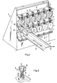
- FIG. 1 three rows of workpiece holders 2, 3, 4 are arranged in a magazine 1 in the form of spaced double plates, which have a plurality of recesses 5 that are open on one side for hanging the workpieces 7 fastened to bolts 6.
- the gripper arm 8 of a manipulator (not shown) carries at its front end a gripping pliers 9, the two gripping jaws 10 of which, on both sides, encompass the stud projecting from the surface of the workpieces 7.
- This gripper arm 8 of the manipulator can be moved in the direction of the arrows 11, 12 and is thus able to remove the workpieces 7 together with the bolts 6 adhered to them from the magazine 1 and to transport them to further processing or storage stations.
- Each of the bolts 6 shown in detail in FIG. 2 has a narrow middle part 13 with an annular flange 14 as well as a disk-shaped foot 15 and a widened hollow cylindrical head 16.
- the interior 17 of the bolts 6 is used to hold a suitable adhesive, e.g. a thermoset 18.
- the lower surface of the disk-shaped foot 15 is e.g. curved inwards so that a sufficient amount of adhesive can penetrate from the interior of the bolt 17 into the space between this curved base and the surface of the workpiece 7, in order to ensure a secure and at the same time releasable connection between the bolt 6 and the workpiece 7 even if the course of the workpiece is uneven Ensure workpiece surface.
- thermosetting plastic is e.g. a spray gun is injected into the interior of the bolt placed on the surface of the workpiece 7.
- the adhesive is selected with regard to its adhesive properties and consistency in such a way that it hardens after a few seconds and establishes a firm connection between the bolt 6 and the workpiece 7.
- a thermoplastic offers itself as an adhesive, which can be reflowed simply by heating the bolt and at the same time regains its adhesive properties.
- the bolts 6 After the workpieces have passed 7 different stations and machining operations, the bolts 6 must be removed from the finished parts. This is done in a simple manner by a lateral impact on the bolt, through which the adhesive connection is released. Depending on the properties of the adhesives, the release of the bolts 6 from the workpieces 7 can also be carried out in other ways, e.g. can be solved by briefly heating or by adding a solvent.
Landscapes
- Engineering & Computer Science (AREA)
- Mechanical Engineering (AREA)
- Manipulator (AREA)
- Jigs For Machine Tools (AREA)
- Feeding Of Workpieces (AREA)
- Automatic Assembly (AREA)
Applications Claiming Priority (2)
| Application Number | Priority Date | Filing Date | Title |
|---|---|---|---|
| DE3123029 | 1981-06-10 | ||
| DE3123029A DE3123029C2 (de) | 1981-06-10 | 1981-06-10 | Werkstück-Handhabungsvorrichtung |
Publications (2)
| Publication Number | Publication Date |
|---|---|
| EP0066849A1 EP0066849A1 (de) | 1982-12-15 |
| EP0066849B1 true EP0066849B1 (de) | 1985-03-20 |
Family
ID=6134367
Family Applications (1)
| Application Number | Title | Priority Date | Filing Date |
|---|---|---|---|
| EP82104876A Expired EP0066849B1 (de) | 1981-06-10 | 1982-06-03 | Handhabungssystem für Werkstücke |
Country Status (4)
| Country | Link |
|---|---|
| US (1) | US4492513A (enExample) |
| EP (1) | EP0066849B1 (enExample) |
| JP (1) | JPS5851050A (enExample) |
| DE (1) | DE3123029C2 (enExample) |
Families Citing this family (8)
| Publication number | Priority date | Publication date | Assignee | Title |
|---|---|---|---|---|
| JPS60146042A (ja) * | 1983-12-29 | 1985-08-01 | 株式会社豊田自動織機製作所 | 流体噴射式織機における緯入れ案内装置 |
| DE4003375C1 (enExample) * | 1990-02-05 | 1991-05-23 | Sfs Stadler Holding Ag, Heerbrugg, Ch | |
| US5152660A (en) * | 1991-05-17 | 1992-10-06 | Atlas Technologies, Inc. | Transfer arm for supporting workpieces |
| US5624513A (en) * | 1995-06-14 | 1997-04-29 | United Technologies Corporation | Removal of inserts from the interiors of turbine airfoils |
| KR20050061455A (ko) * | 2002-08-07 | 2005-06-22 | 더 펜 스테이트 리서치 파운데이션 | 제조 고정구에 대한 공작물의 결합과 분리를 위한 시스템및 방법 |
| US7524390B2 (en) * | 2006-03-27 | 2009-04-28 | The Penn State Research Foundation | Fixture and method of holding and debonding a workpiece with the fixture |
| DK2434141T3 (en) | 2010-09-24 | 2016-02-01 | Siemens Ag | A device for handling a wind turbine component |
| CN108620910B (zh) * | 2018-04-20 | 2019-09-06 | 东莞理工学院 | 适用于不规则工件的夹持方法和装置 |
Citations (1)
| Publication number | Priority date | Publication date | Assignee | Title |
|---|---|---|---|---|
| DE1957608A1 (de) * | 1968-11-15 | 1970-07-23 | Rolls Royce | Verfahren zur Bildung einspannbarer Halterungen an Werkstuecken zwecks deren Bearbeitung |
Family Cites Families (7)
| Publication number | Priority date | Publication date | Assignee | Title |
|---|---|---|---|---|
| US3045620A (en) * | 1956-12-10 | 1962-07-24 | Buck Mfg Company | Unitary portable electromagnetic clamp |
| US3702703A (en) * | 1971-11-24 | 1972-11-14 | Clair O Du Bois | Cribage board and container assembly for dominoes |
| GB1451205A (en) * | 1972-12-29 | 1976-09-29 | Aerospatiale | Shaping machine with servo-assisted forming roll |
| US4074519A (en) * | 1977-03-31 | 1978-02-21 | American Hoist & Derrick Company | Swivel shackle |
| US4130921A (en) * | 1977-07-15 | 1978-12-26 | Melvin Wallshein | Method of making orthodontic appliance having replaceable tooth engaging means |
| FR2434686A1 (fr) * | 1978-09-04 | 1980-03-28 | Bohle Josef | Preneur a ventouse |
| US4348044A (en) * | 1980-10-10 | 1982-09-07 | Cincinnati Milacron Inc. | Article gripping apparatus |
-
1981
- 1981-06-10 DE DE3123029A patent/DE3123029C2/de not_active Expired
-
1982
- 1982-06-03 EP EP82104876A patent/EP0066849B1/de not_active Expired
- 1982-06-07 US US06/385,835 patent/US4492513A/en not_active Expired - Fee Related
- 1982-06-09 JP JP57097870A patent/JPS5851050A/ja active Granted
Patent Citations (1)
| Publication number | Priority date | Publication date | Assignee | Title |
|---|---|---|---|---|
| DE1957608A1 (de) * | 1968-11-15 | 1970-07-23 | Rolls Royce | Verfahren zur Bildung einspannbarer Halterungen an Werkstuecken zwecks deren Bearbeitung |
Also Published As
| Publication number | Publication date |
|---|---|
| JPH0238340B2 (enExample) | 1990-08-30 |
| US4492513A (en) | 1985-01-08 |
| JPS5851050A (ja) | 1983-03-25 |
| EP0066849A1 (de) | 1982-12-15 |
| DE3123029A1 (de) | 1982-12-30 |
| DE3123029C2 (de) | 1985-05-09 |
Similar Documents
| Publication | Publication Date | Title |
|---|---|---|
| DE3320762C2 (de) | Stanzmaschine mit einem stationären Magazin | |
| EP0117557B1 (de) | Werkstückpalette an Werkzeugmaschinen | |
| DE19844242C2 (de) | Universalschleifmaschine | |
| EP0216261A2 (de) | Werkzeugmaschine | |
| DE2444124B2 (de) | Einrichtung zum automatischen Beschicken von Werkzeugmaschinen | |
| EP0638010B1 (de) | Verfahren und vorrichtung zum automatischen assemblieren und bearbeiten von mehreren bauteilen | |
| EP1860593B1 (de) | Stationärmaschine zum Anbringen von Kantenmaterial an plattenförmige Werkstücke | |
| EP0066849B1 (de) | Handhabungssystem für Werkstücke | |
| WO2000066319A1 (de) | Werkzeugmaschine mit einem manipulator | |
| DE2303198B2 (de) | Vorrichtung zum automatischen, gleichzeitigen und kontinuierlichen Schweißen von mehreren Kraftfahrzeugrädern oder dergleichen Werkstücken | |
| EP0309444A2 (de) | Palette zur Bereitstellung, zur Aufnahme und zum Transport von Werkstücken | |
| DE7737111U1 (de) | Vorrichtung zum beladen von werkzeugmaschinen, insbesondere drehmaschinen | |
| DE3428992C1 (de) | Einrichtung zum selbsttätigen Beschicken von mehreren Arbeitsstationen, bspw. Werkzeugmaschinen, mit Werkstücken | |
| CH663190A5 (de) | Belade- und entladeeinrichtung fuer werkstuecktraeger. | |
| DE4100148A1 (de) | Palette zur bereitstellung, zur aufnahme und zum transport von werkstuecken | |
| DE102006036981A1 (de) | Verfahren und Vorrichtung zum Befestigen eines Befestigungselements an einem Werkstück | |
| DE2848155A1 (de) | Montageautomat fuer das montieren der raeder an eine fahrzeugkarosserie | |
| DE102023116977A1 (de) | Bestückungsautomat für Kunststoffteile und Verfahren zum Bestücken von Kunststoffteilen | |
| DE1777465B1 (de) | Mehrspindeldrehautomat | |
| DE2258398C3 (de) | Verfahren und Vorrichtung zum In-Verbindung-Bringen eines Linsenrohlings mit einem Linsenhalter und Zuführen des Linsenrohlings zur Bearbeitungsstation einer Maschine zum Schleifen und Polieren von Linsen | |
| DE8117205U1 (de) | Griffteil zur Handhabung von Werkstücken | |
| DE933798C (de) | Einrichtung zur Fertigung am Fliessband | |
| DE4116104C1 (en) | Machine tool for spark erosion machines - has magazine for tool and workpiece storage | |
| DE69001333T2 (de) | Maschine und verfahren zum bearbeiten und/oder fertigbearbeiten von gegossenen oder bearbeiteten werkstuecken. | |
| DE102010052303B4 (de) | Verfahren und Einrichtung zur überlappenden Bearbeitung flächiger Gegenstände |
Legal Events
| Date | Code | Title | Description |
|---|---|---|---|
| PUAI | Public reference made under article 153(3) epc to a published international application that has entered the european phase |
Free format text: ORIGINAL CODE: 0009012 |
|
| AK | Designated contracting states |
Designated state(s): CH FR GB IT LI |
|
| 17P | Request for examination filed |
Effective date: 19821229 |
|
| ITF | It: translation for a ep patent filed | ||
| GRAA | (expected) grant |
Free format text: ORIGINAL CODE: 0009210 |
|
| AK | Designated contracting states |
Designated state(s): CH FR GB IT LI |
|
| ET | Fr: translation filed | ||
| PLBE | No opposition filed within time limit |
Free format text: ORIGINAL CODE: 0009261 |
|
| STAA | Information on the status of an ep patent application or granted ep patent |
Free format text: STATUS: NO OPPOSITION FILED WITHIN TIME LIMIT |
|
| 26N | No opposition filed | ||
| REG | Reference to a national code |
Ref country code: FR Ref legal event code: CN |
|
| REG | Reference to a national code |
Ref country code: CH Ref legal event code: PFA Free format text: MAHO AKTIENGESELLSCHAFT |
|
| PGFP | Annual fee paid to national office [announced via postgrant information from national office to epo] |
Ref country code: FR Payment date: 19910326 Year of fee payment: 10 |
|
| PGFP | Annual fee paid to national office [announced via postgrant information from national office to epo] |
Ref country code: CH Payment date: 19910501 Year of fee payment: 10 |
|
| PGFP | Annual fee paid to national office [announced via postgrant information from national office to epo] |
Ref country code: GB Payment date: 19910520 Year of fee payment: 10 |
|
| ITTA | It: last paid annual fee | ||
| PG25 | Lapsed in a contracting state [announced via postgrant information from national office to epo] |
Ref country code: GB Effective date: 19920603 |
|
| PG25 | Lapsed in a contracting state [announced via postgrant information from national office to epo] |
Ref country code: LI Effective date: 19920630 Ref country code: CH Effective date: 19920630 |
|
| GBPC | Gb: european patent ceased through non-payment of renewal fee |
Effective date: 19920603 |
|
| PG25 | Lapsed in a contracting state [announced via postgrant information from national office to epo] |
Ref country code: FR Effective date: 19930226 |
|
| REG | Reference to a national code |
Ref country code: CH Ref legal event code: PL |
|
| REG | Reference to a national code |
Ref country code: FR Ref legal event code: ST |