EP0066407B2 - Hin- und hergehende Pumpe für Unterdruckerzeugung - Google Patents
Hin- und hergehende Pumpe für Unterdruckerzeugung Download PDFInfo
- Publication number
- EP0066407B2 EP0066407B2 EP19820302528 EP82302528A EP0066407B2 EP 0066407 B2 EP0066407 B2 EP 0066407B2 EP 19820302528 EP19820302528 EP 19820302528 EP 82302528 A EP82302528 A EP 82302528A EP 0066407 B2 EP0066407 B2 EP 0066407B2
- Authority
- EP
- European Patent Office
- Prior art keywords
- chamber
- exhaust
- valve
- pump member
- exhauster
- Prior art date
- Legal status (The legal status is an assumption and is not a legal conclusion. Google has not performed a legal analysis and makes no representation as to the accuracy of the status listed.)
- Expired - Lifetime
Links
Images
Classifications
-
- B—PERFORMING OPERATIONS; TRANSPORTING
- B60—VEHICLES IN GENERAL
- B60T—VEHICLE BRAKE CONTROL SYSTEMS OR PARTS THEREOF; BRAKE CONTROL SYSTEMS OR PARTS THEREOF, IN GENERAL; ARRANGEMENT OF BRAKING ELEMENTS ON VEHICLES IN GENERAL; PORTABLE DEVICES FOR PREVENTING UNWANTED MOVEMENT OF VEHICLES; VEHICLE MODIFICATIONS TO FACILITATE COOLING OF BRAKES
- B60T17/00—Component parts, details, or accessories of power brake systems not covered by groups B60T8/00, B60T13/00 or B60T15/00, or presenting other characteristic features
-
- F—MECHANICAL ENGINEERING; LIGHTING; HEATING; WEAPONS; BLASTING
- F04—POSITIVE - DISPLACEMENT MACHINES FOR LIQUIDS; PUMPS FOR LIQUIDS OR ELASTIC FLUIDS
- F04B—POSITIVE-DISPLACEMENT MACHINES FOR LIQUIDS; PUMPS
- F04B35/00—Piston pumps specially adapted for elastic fluids and characterised by the driving means to their working members, or by combination with, or adaptation to, specific driving engines or motors, not otherwise provided for
- F04B35/002—Piston pumps specially adapted for elastic fluids and characterised by the driving means to their working members, or by combination with, or adaptation to, specific driving engines or motors, not otherwise provided for driven by internal combustion engines
-
- F—MECHANICAL ENGINEERING; LIGHTING; HEATING; WEAPONS; BLASTING
- F04—POSITIVE - DISPLACEMENT MACHINES FOR LIQUIDS; PUMPS FOR LIQUIDS OR ELASTIC FLUIDS
- F04B—POSITIVE-DISPLACEMENT MACHINES FOR LIQUIDS; PUMPS
- F04B37/00—Pumps having pertinent characteristics not provided for in, or of interest apart from, groups F04B25/00 - F04B35/00
- F04B37/10—Pumps having pertinent characteristics not provided for in, or of interest apart from, groups F04B25/00 - F04B35/00 for special use
- F04B37/14—Pumps having pertinent characteristics not provided for in, or of interest apart from, groups F04B25/00 - F04B35/00 for special use to obtain high vacuum
Definitions
- This invention relates to a reciprocating exhauster of the kind used to provide vacuum to operate a vehicle braking servo predominantly on vehicles driven by diesel engines.
- Such exhausters are known which are operated by an engine-driven cam acting on the piston or push rod.
- an inlet valve which may be a reed- type or disc-type valve, is fitted in the connection between the vacuum reservoir and the cylinder and an exhaust valve in communication with the clearance volume (i.e. cylinder volume at top dead centre) is fitted in the cylinder casing.
- the performance of such exhausters depends to a considerable extent upon the size of the clearance volume which is critically affected by component tolerances.
- British Patent Specification No. 2,003,990A discloses a vacuum pump or exhauster which is driven by the engine cam shaft and includes a reciprocable pump member operable to withdraw air from an inlet and expel it to atmosphere.
- the pump member which may be a diaphragm or a piston divides the cylinder body into an inlet chamber and an outlet chamber, the body and the pump member being so shaped as to minimise the clearance volume of the inlet chamber which is the primary pumping chamber. Air passes through a check valve in a flow path through the pump member, to the exhaust chamber, which has a relatively large minimum volume, intended to increase the pump efficiency while at the same time reducing the noise attributable to gas discharge from the primary pump chamber.
- GB-A-2 040 361A discloses a pump for fitment to an engine crankcase into which exhaust ports discharge directly.
- this pump when large airflows are required, for example for initial stages of evacuation, the two pumping chambers operate in parallel; while when a higher degree of evacuation is required, the mode of operation changes over, with the two chambers then operating in series. The change over is governed by the characteristics of the springs acting on the various valve closure members.
- a reciprocating exhauster for mounting on the engine casing of a motor vehicle to be driven by the engine and comprising a pump member working in a cylinder body so as to define on opposite sides thereof an inlet chamber having an inlet for connection to a vacuum reservoir and an exhaust chamber having an outlet fitted with an exhaust valve on the side of the exhaust chamber remote from the pump member and a valve arranged to permit fluid to flow from the inlet chamber to the exhaust chamber,
- the pump member being driven is one direction by a push rod against the action of a return spring disposed in one of the chambers of the cylinder body which spring drives the pump member in the return direction, the push rod passing through the other chamber without the spring and the pump member and the cylinder body being so shaped that the clearance volume of said chamber whithout the spring is minimised and said chamber constitute the main pumping chamber wereas the chamberwith the sping comprises a large clearance volume chamber, characterised in that the main pumping chamber is the exhaust chamber the exhaust value and the side of the exhaust chamber remote from the pump member are
- the pump member in conventional reciprocating exhausters, is driven by a cam acting directly on the push rod (the piston rod) the return spring disposed in the inlet chamber also serving to bias the push rod into contact with the cam.
- the inlet to the inlet chamber is fitted with a non-return valve which serves to increase the efficiency of the exhauster. If, however, no non-return valve is fitted the inlet chamber effectively provides additional vacuum reservoir capacity.
- the invention enables a simpler and cheaper construction due, in part, to the relative ease with which component tolerances can be controlled, than is possible with conventional piston exhausters and in which different strokes can be accommodated with minimal component changes.
- the present invention differs from the exhauster disclosed in British Patent Specification 2,003,990 in that the flow through the two chambers of different clearance volumes is in the opposite direction. That is: the air first enters the chamber with high clearance volume and not as in GB-A-2,003,990, the low clearance volume chamber.
- the exhaust chamber is the main pumping chamber.
- the exhaust port is positioned on the piston or push rod side of the exhaust chamber, this having an advantage in that the exhaust air can be discharged directly into the engine crankcase on which the exhauster is mounted, so avoiding the problem of noise generated by the exhaust valve, and the inlet is conveniently located away from the mounting flange. Also, this arrangement enables the exhauster according to the present invention to be more compact than conventional exhausters and facilitates the admission to the pumping chamber of oil from the crankcase for sealing and lubrication. The oil is then returned to the crankcase with the exhaust air. In a piston exhauster arranged as described in British Patent No. 2,003,990 oil entering the pump chamber would be discharged into the atmosphere unless an additional pipe is connected between the exhaust port and the crankcase.
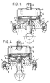
- the piston exhauster is bolted onto the engine crankcase Q through which passes a piston push rod A, within a bearing E and in engagement with an engine driven cam.
- the piston rod is sealed by a low-friction ring seal L.
- a piston C bolted to the piston rod A and carrying a low-friction piston ring seal J held by a floating retainer I upon which a return spring H acts directly so clamping the seal J.
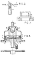
- piston C is a high clearance volume inlet chamber in direct communication with a vacuum reservoir (not shown) via a pipe S and the space created between the piston C and the base block F as the piston works within the cylinder G moving away from the position (equivalent to top-dead centre) illustrated, is a low clearance volume exhaust chamber communicating with the interior of the crankcase Q via an exhaust valve K which may be a disc-type check or non-return valve, such as shown in Figure 3, let into a recess in the base block F.
- exhaust valve K may be a disc-type check or non-return valve, such as shown in Figure 3, let into a recess in the base block F.
- the pressing G is secured to the block F by crimping, accurate machining of the pressing G therefore being unnecessary since, provided the block F is accurately machined, the block F serves to size the cylinder bore during assembly to provide a good piston seal.
- Static O-ring seals M and N are fitted between the pressing G and the external diameter of the block F, and between the block F and the engine crankcase Q, respectively.
- a flap valve B is clamped between the piston C and piston rod A so as to cover four equally angularly spaced holes passing through the piston.
- the valve B In the position (top-dead centre of the exhaust stage) shown in Figure 1, the valve B is received within a recess in the block F so minimising the clearance volume of the exhaust chamber.
- the piston rod A and piston and seal assembly (B, C, D, I and J) are displaced upwardly against the action of the return spring H, thus creating a partial vacuum on the lower side of the piston (i.e. in the exhaust chamber).
- the flap-valve B opens to admit airfrom the inlet chamber (in communication with the vacuum reservoir), to the exhaust chamber.
- the piston is driven downwardly by the return spring H to exhaust air in the exhaust chamber through the check valve K directly into the engine crankcase.
- the block F may be allowed to protrude slightly from the cylinder body pressing G so that when mounting the exhauster the bolts P draw the cylinder body pressing to the crankcase flange ensuring that the block F is in contact with the flange.
- Figure 5 shows another embodiment of piston exhauster which is similar in principle to the exhauster of Figure 4, but in which the bearing E is replaced by a bore in the block F, and the seal L is omitted. Also, the piston is of a one piece construction and the flap valve B which covers two annular grooves in the face of the piston has a supporting washer.
Claims (2)
Applications Claiming Priority (2)
| Application Number | Priority Date | Filing Date | Title |
|---|---|---|---|
| GB8115548 | 1981-05-20 | ||
| GB8115548 | 1981-05-20 |
Publications (4)
| Publication Number | Publication Date |
|---|---|
| EP0066407A2 EP0066407A2 (de) | 1982-12-08 |
| EP0066407A3 EP0066407A3 (en) | 1983-09-21 |
| EP0066407B1 EP0066407B1 (de) | 1985-06-26 |
| EP0066407B2 true EP0066407B2 (de) | 1993-03-24 |
Family
ID=10521950
Family Applications (1)
| Application Number | Title | Priority Date | Filing Date |
|---|---|---|---|
| EP19820302528 Expired - Lifetime EP0066407B2 (de) | 1981-05-20 | 1982-05-18 | Hin- und hergehende Pumpe für Unterdruckerzeugung |
Country Status (5)
| Country | Link |
|---|---|
| EP (1) | EP0066407B2 (de) |
| BR (1) | BR8202906A (de) |
| DE (1) | DE3264411D1 (de) |
| ES (1) | ES512367A0 (de) |
| IN (1) | IN156557B (de) |
Families Citing this family (2)
| Publication number | Priority date | Publication date | Assignee | Title |
|---|---|---|---|---|
| US4568011A (en) * | 1984-12-14 | 1986-02-04 | Dearmitt Clyde B | Vacuum pump for desoldering gun |
| DE4304786A1 (de) * | 1993-02-17 | 1994-08-18 | Zeolith Tech | Handbetätigbare Vakuumpumpe |
Family Cites Families (2)
| Publication number | Priority date | Publication date | Assignee | Title |
|---|---|---|---|---|
| GB841275A (en) * | 1958-06-30 | 1960-07-13 | Acf Ind Inc | Piston type suction booster pump |
| US4156416A (en) * | 1977-09-09 | 1979-05-29 | General Motors Corporation | Engine driven vacuum pump |
-
1982
- 1982-05-18 EP EP19820302528 patent/EP0066407B2/de not_active Expired - Lifetime
- 1982-05-18 DE DE8282302528T patent/DE3264411D1/de not_active Expired
- 1982-05-19 BR BR8202906A patent/BR8202906A/pt unknown
- 1982-05-19 ES ES512367A patent/ES512367A0/es active Granted
- 1982-05-20 IN IN575/CAL/82A patent/IN156557B/en unknown
Also Published As
| Publication number | Publication date |
|---|---|
| EP0066407A2 (de) | 1982-12-08 |
| ES8306652A1 (es) | 1983-06-16 |
| DE3264411D1 (en) | 1985-08-01 |
| EP0066407B1 (de) | 1985-06-26 |
| ES512367A0 (es) | 1983-06-16 |
| BR8202906A (pt) | 1983-05-03 |
| IN156557B (de) | 1985-08-31 |
| EP0066407A3 (en) | 1983-09-21 |
Similar Documents
| Publication | Publication Date | Title |
|---|---|---|
| US4137020A (en) | Diaphragm type air pump | |
| US4854825A (en) | Multi-stage vacuum pump | |
| KR100226037B1 (ko) | 펌프 | |
| EP0731274B1 (de) | Mehrstufige Vakuumpumpe | |
| US4738595A (en) | Hydraulic pump with integrated sump and accumulator | |
| KR20040020037A (ko) | 전체 길이가 감소된 기체용 왕복 피스톤 압축기 | |
| US5022832A (en) | Ring valve type air compressor | |
| KR880001938A (ko) | 구동장치 | |
| CA2251105A1 (en) | Reciprocating liquid pump with disc check valve | |
| US5503537A (en) | Gas compressor | |
| EP0437314B1 (de) | Auslassventil-Mechanismus eines Kühlverdichters | |
| US4006797A (en) | Cam actuated lubrication pump | |
| CA1122479A (en) | Double-acting differential piston supply pump | |
| US4525128A (en) | Reciprocating exhauster | |
| EP0066407B2 (de) | Hin- und hergehende Pumpe für Unterdruckerzeugung | |
| JPH06280743A (ja) | 油圧系のためのポンプ | |
| US4050861A (en) | Diaphragm pump | |
| CA2379641A1 (en) | Double acting, two-stage pump | |
| US5716198A (en) | Radial piston pump | |
| JPH0125895B2 (de) | ||
| US5618165A (en) | Variable displacement and constant pressure pump | |
| US5967178A (en) | Flow-controlled one-way valve | |
| US4541788A (en) | Diaphragm fluid pump | |
| RU2004139024A (ru) | Пневматический клапан для тормозных систем | |
| CN110249130B (zh) | 具有棱柱形活塞的无油真空泵和相应的压缩机 |
Legal Events
| Date | Code | Title | Description |
|---|---|---|---|
| PUAI | Public reference made under article 153(3) epc to a published international application that has entered the european phase |
Free format text: ORIGINAL CODE: 0009012 |
|
| AK | Designated contracting states |
Designated state(s): DE FR GB IT SE |
|
| PUAL | Search report despatched |
Free format text: ORIGINAL CODE: 0009013 |
|
| AK | Designated contracting states |
Designated state(s): DE FR GB IT SE |
|
| 17P | Request for examination filed |
Effective date: 19830926 |
|
| ITF | It: translation for a ep patent filed |
Owner name: UFFICIO BREVETTI RICCARDI & C. |
|
| GRAA | (expected) grant |
Free format text: ORIGINAL CODE: 0009210 |
|
| AK | Designated contracting states |
Kind code of ref document: B1 Designated state(s): DE FR GB IT SE |
|
| REF | Corresponds to: |
Ref document number: 3264411 Country of ref document: DE Date of ref document: 19850801 |
|
| ET | Fr: translation filed | ||
| PLBI | Opposition filed |
Free format text: ORIGINAL CODE: 0009260 |
|
| 26 | Opposition filed |
Opponent name: PIERBURG GMBH & CO KG Effective date: 19860317 |
|
| PLAB | Opposition data, opponent's data or that of the opponent's representative modified |
Free format text: ORIGINAL CODE: 0009299OPPO |
|
| R26 | Opposition filed (corrected) |
Opponent name: PIERBURG GMBH Effective date: 19860317 |
|
| ITTA | It: last paid annual fee | ||
| RAP4 | Party data changed (patent owner data changed or rights of a patent transferred) |
Owner name: WABCO AUTOMOTIVE U.K. LIMITED |
|
| PUAH | Patent maintained in amended form |
Free format text: ORIGINAL CODE: 0009272 |
|
| STAA | Information on the status of an ep patent application or granted ep patent |
Free format text: STATUS: PATENT MAINTAINED AS AMENDED |
|
| 27A | Patent maintained in amended form |
Effective date: 19930324 |
|
| AK | Designated contracting states |
Kind code of ref document: B2 Designated state(s): DE FR GB IT SE |
|
| ITF | It: translation for a ep patent filed |
Owner name: UFFICIO BREVETTI RICCARDI & C. |
|
| EN3 | Fr: translation not filed ** decision concerning opposition | ||
| REG | Reference to a national code |
Ref country code: FR Ref legal event code: R1 |
|
| ET3 | Fr: translation filed ** decision concerning opposition | ||
| REG | Reference to a national code |
Ref country code: FR Ref legal event code: DS |
|
| EAL | Se: european patent in force in sweden |
Ref document number: 82302528.3 |
|
| APAC | Appeal dossier modified |
Free format text: ORIGINAL CODE: EPIDOS NOAPO |
|
| APAC | Appeal dossier modified |
Free format text: ORIGINAL CODE: EPIDOS NOAPO |
|
| PGFP | Annual fee paid to national office [announced via postgrant information from national office to epo] |
Ref country code: GB Payment date: 20010508 Year of fee payment: 20 |
|
| PGFP | Annual fee paid to national office [announced via postgrant information from national office to epo] |
Ref country code: SE Payment date: 20010510 Year of fee payment: 20 |
|
| PGFP | Annual fee paid to national office [announced via postgrant information from national office to epo] |
Ref country code: DE Payment date: 20010523 Year of fee payment: 20 |
|
| PGFP | Annual fee paid to national office [announced via postgrant information from national office to epo] |
Ref country code: FR Payment date: 20010530 Year of fee payment: 20 |
|
| REG | Reference to a national code |
Ref country code: GB Ref legal event code: IF02 |
|
| PG25 | Lapsed in a contracting state [announced via postgrant information from national office to epo] |
Ref country code: GB Free format text: LAPSE BECAUSE OF EXPIRATION OF PROTECTION Effective date: 20020517 |
|
| REG | Reference to a national code |
Ref country code: GB Ref legal event code: PE20 Effective date: 20020517 |
|
| EUG | Se: european patent has lapsed |
Ref document number: 82302528.3 |
|
| APAH | Appeal reference modified |
Free format text: ORIGINAL CODE: EPIDOSCREFNO |