EP0066314A2 - Gripper for forming clamps for connecting flexible hoses to pipes - Google Patents
Gripper for forming clamps for connecting flexible hoses to pipes Download PDFInfo
- Publication number
- EP0066314A2 EP0066314A2 EP82200561A EP82200561A EP0066314A2 EP 0066314 A2 EP0066314 A2 EP 0066314A2 EP 82200561 A EP82200561 A EP 82200561A EP 82200561 A EP82200561 A EP 82200561A EP 0066314 A2 EP0066314 A2 EP 0066314A2
- Authority
- EP
- European Patent Office
- Prior art keywords
- gripper
- tooth
- teeth
- lever
- arm
- Prior art date
- Legal status (The legal status is an assumption and is not a legal conclusion. Google has not performed a legal analysis and makes no representation as to the accuracy of the status listed.)
- Withdrawn
Links
Images

Classifications
-
- B—PERFORMING OPERATIONS; TRANSPORTING
- B25—HAND TOOLS; PORTABLE POWER-DRIVEN TOOLS; MANIPULATORS
- B25B—TOOLS OR BENCH DEVICES NOT OTHERWISE PROVIDED FOR, FOR FASTENING, CONNECTING, DISENGAGING OR HOLDING
- B25B25/00—Implements for fastening, connecting or tensioning of wire or strip
- B25B25/005—Implements for fastening, connecting or tensioning of wire or strip for applying wire clasps to hose couplings
Definitions
- the invention relates to a gripper for forming clamps for connecting flexible hoses to pipes.
- the object of the invention is to provide a gripper able to form such clamps by means of a single operation, to ensure that the hose is properly tightened on its rigid connection element in all circumstances, i.e. independently of the rigidity or compressibility of the hose and its diameter.
- a clamp can be made by this gripper in a time much shorter than that used at present and with decidedly better results from the point of view of clamping rigidity, appearance of the finished clamp, and its cost.
- a gripper for forming clamps for connecting flexible hoses to pipes characterised by comprising two arms or handles hinged together in order to rotate in parallel planes, one arm being provided.
- the other arm being provided at its end opposite the hinging pivot with two teeth orthogonal to the plane of rotation of the arms and separated by a slot
- the other arm being provided at its end opposite the hinging pivot with an arcuate hook-shaped tooth which is also orthogonal to the plane of rotation of the arms and extends on the same side as the first two teeth
- on the arm provided with the two teeth there being hinged a lever which can be rotated manually against elastic means and is provided with a tooth which is substantially parallel to the two first teeth and is mobile by manual action between a position of approach to said two first teeth and a position of withdrawal therefrom;
- the hook tooth being arranged to hook the loop of an iron wire wound about a hose, and the slot between the two first teeth being arranged to receive the free ends of said iron wire, which can be clamped to the gripper by tightening the lever tooth against the adjacent . tooth with the wire ends therebetween.
- the gripper according to the invention consists of two substantially circumferential plates 10 and 11 each provided with an arm 12 acting as a handle.
- the plates 10 and 11 are hinged together at 13.
- Two side-by-side orthogonal bent portions l4 and 15 are provided on the plate 10 to form two teeth, between which there is a slot l6.
- a lever 20 terminating at one end in a bent edge 21 to form a tooth, which constitutes a continuity with the two adjacent teeth 14 and 15 of the plate 10.
- the other end 22 of the lever 20 abuts against the end of a threaded pin 23 screwed into a sleeve 24 which is also threaded and is rigid with the arm 12 of the disc 10. That end of the pin 23 distant from the end against which the lever 20 abuts is provided with a wing nut 25 to enable it to be screwed in and out manually.
- a spring 26 is stretched between the end 22 of the lever 20 and the arm 12 of the disc 10 to ensure that the end 22 abuts against the pin 23 continuously.
- the wing nut 25 ( Figure 1) is rotated in the clockwise direction shown by the arrow A, thus making the pin 23 press against the end 22 of the lever 20. Its tooth 21 thus approaches the adjacent tooth 14 in the direction of the arrow B against the action of the spring 23, until they clamp the wire 30 between them as shown in Figure 4.
- each of the two plates 10 and 11 can be provided with a slot 33 into which the ends are inserted at the point to be cut.
- the slots move away from each other angularly to act as a cutter, so breaking the ends.
- the gripper heretofore described and illustrated has been reduced to its essentials for the purposes of description, but it is clear that it can be made of more aesthetic appearance, and the handles 12 will be covered, in order to hide the various components used for rotating the lever 20.
Abstract
A gripper constituted by two discs hinged to each other in order to rotate in parallel planes, each disc being provided with a handle arm, one of said discs being provided on its periphery with two teeth orthogonal to the plane of rotation and separated by a slot, and the other of said discs being provided on its periphery with a tooth which is also orthogonal to the plane of rotation and is configured as an arcuate hook pointing outwards; a tooth is hinged to the first arm so that it can be made to withdraw from and approach the two teeth of said arm. The loop of an iron wire wound about the end of a flexible hose is hooked on to the hook, while the ends of the wire are passed through the slot and through the space between the mobile tooth and the tooth adjacent to it. The wire ends are held rigid by moving the mobile tooth against them, and the gripper is then rotated by means of its two arms in order to move the hook away from the point at which the wire ends are held rigid, so tightening the wire about the hose and producing a properly tightened clamp.
Description
- The invention relates to a gripper for forming clamps for connecting flexible hoses to pipes.
- One, of the drawbacks of flexible hoses is that their ends have often to be connected to nozzles, bayonet connectors or rigid connectors. Such connections are often made by means of metal clamps which are wrapped rigidly about the end of the hose over that portion into which is inserted the rigid element to which the hose is to be connected.
- Because of the compressibility of the hose wall, the more the clamp is tightened the better the connection between the hose and the rigid element to which it is to be connected.
- The formation of such a clamp is however laborious, and only rarely is a satisfactory grip on the flexible hose attained. This is because the clamp is often tightened using makeshift means, pincers or pliers of conventional type, and often the wire ends are bent back and twisted together with the bare hands, with the frequent risk of injury, but without obtaining satisfactory results.
- If such connections have to be made regularly during industrial manufacturing operations, such operations become extremely costly and the result so varies from piece to piece that no reliability can be assured.
- The object of the invention is to provide a gripper able to form such clamps by means of a single operation, to ensure that the hose is properly tightened on its rigid connection element in all circumstances, i.e. independently of the rigidity or compressibility of the hose and its diameter. In addition, a clamp can be made by this gripper in a time much shorter than that used at present and with decidedly better results from the point of view of clamping rigidity, appearance of the finished clamp, and its cost.
- These and further objects which will be more apparent hereinafter are attained according to the invention by a gripper for forming clamps for connecting flexible hoses to pipes, characterised by comprising two arms or handles hinged together in order to rotate in parallel planes, one arm being provided. at its end opposite the hinging pivot with two teeth orthogonal to the plane of rotation of the arms and separated by a slot, the other arm being provided at its end opposite the hinging pivot with an arcuate hook-shaped tooth which is also orthogonal to the plane of rotation of the arms and extends on the same side as the first two teeth; on the arm provided with the two teeth there being hinged a lever which can be rotated manually against elastic means and is provided with a tooth which is substantially parallel to the two first teeth and is mobile by manual action between a position of approach to said two first teeth and a position of withdrawal therefrom; the hook tooth being arranged to hook the loop of an iron wire wound about a hose, and the slot between the two first teeth being arranged to receive the free ends of said iron wire, which can be clamped to the gripper by tightening the lever tooth against the adjacent . tooth with the wire ends therebetween.
- A preferred embodiment of the gripper according to the invention is described hereinafter with reference to the accompanying drawings, in which:
- Figure 1 is a frontal view of the gripper;
- Figure 2 is a perspective view of the end of a hose on which a clamp is to be fitted;
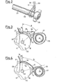
- Figures 3 and 4 are two successive positions in the application of the clamp using the gripper according to the invention;
- Figure 5 shows the position of the clamp at the moment when the gripper is removed therefrom;
- Figure 6 is a view of the finished clamp.
- The gripper according to the invention consists of two substantially
circumferential plates arm 12 acting as a handle. Theplates - Two side-by-side orthogonal bent portions l4 and 15 are provided on the
plate 10 to form two teeth, between which there is a slot l6. - On the
plate 11 there is formed only oneorthogonal bent portion 17, of substantially triangular shape and terminating at its end with a slightlyarcuate point 18 which is bent outwards to form a type of hook. - On the
plate 10 there is also hinged at 19 alever 20 terminating at one end in abent edge 21 to form a tooth, which constitutes a continuity with the twoadjacent teeth plate 10. - The
other end 22 of thelever 20 abuts against the end of a threadedpin 23 screwed into asleeve 24 which is also threaded and is rigid with thearm 12 of thedisc 10. That end of thepin 23 distant from the end against which thelever 20 abuts is provided with awing nut 25 to enable it to be screwed in and out manually. Finally, aspring 26 is stretched between theend 22 of thelever 20 and thearm 12 of thedisc 10 to ensure that theend 22 abuts against thepin 23 continuously. - Having examined the structure of the gripper (Figure 1), its use will now be described with reference to Figures 2 to 6.
- Consider any pipe assembly in which a
rigid union 28 is to be connected to one end of aflexible hose 27. The union comprises atubular portion 29 which is inserted with little slack into the end of thehose 27 in known manner. A piece ofiron wire 30 is then taken and is wrapped, as shown in Figure 2, about the end of thehose 27 which internally carries thetubular portion 29 of theunion 28. - As can be seen in Figure 3, holding the
gripper arms 12 open so that the distance a between theslot 16 andhook 18 is a minimum, the two ends of thewire 30 are passed over thetooth 15, through theslot 16, under thetooth 17 and through the space between thetooth 17 andtooth 21 of thelever 20. At the same time, theloop 31 of thewire 30 is hooked on to thehook 18 of theplate 11. - In order to securely clamp the wire to the gripper, the wing nut 25 (Figure 1) is rotated in the clockwise direction shown by the arrow A, thus making the
pin 23 press against theend 22 of thelever 20. Itstooth 21 thus approaches theadjacent tooth 14 in the direction of the arrow B against the action of thespring 23, until they clamp thewire 30 between them as shown in Figure 4. - At this point, by pulling the two
handles 12 together with the hand so that they lie one over the other, the twoplates slot 16 andhook 18 gradually increases until it equals the maximum distance which corresponds approximately to the distance b of Figure 4. Because of the fact that the free ends of thewire 30 held between theteeth hose 27 gradually becomes reduced in diameter until it is tightly clamped about thehose 27 as shown in Figure 5. This is done not only by closing thearms 12 but also by slightly rotating the gripper about thehose 27 in order to prevent any accidental withdrawing of thewire 30 from theloop 31 when the gripper is unhooked. Unhooking is done simply by unscrewing thepin 23,. thus withdrawing thetooth 21 from thetooth 14 and releasing the ends of thewire 30. It is now only necessary to bend back theends 30 on to theloop 31 in the direction of the arrow C of Figure 5, and finally cut the ends to size as shown in Figure 6, then hammering them on to thehose 27, thus completing the operation. In order to cut the ends, each of the twoplates slot 33 into which the ends are inserted at the point to be cut. Thus, on rotating the twoplates - The gripper heretofore described and illustrated has been reduced to its essentials for the purposes of description, but it is clear that it can be made of more aesthetic appearance, and the
handles 12 will be covered, in order to hide the various components used for rotating thelever 20. - These and all other shape and structural modifications lie within the scope of the invention as protected by the following claims.
Claims (5)
1. A gripper for forming clamps for connecting flexible hoses to pipes, characterised by comprising two arms or handles hinged together in order to rotate in parallel planes, one arm being provided at its end opposite the hinging pivot with two teeth orthogonal to the plane of rotation of the arms and separated by a slot, the other arm being provided at its end opposite the hinging pivot with an arcuate hook-shaped tooth which is also orthogonal to the plane of rotation of the arms and extends on the same side as the first two teeth; on the arm provided with the two teeth there being hinged a lever which can be rotated manually against elastic means and is provided with a tooth which is substantially parallel to the two first teeth and is mobile by manual action between a position of approach to said two first teeth and a position of withdrawal therefrom; the hook tooth being arranged to hook the loop of an iron wire wound about a hose, and the slot between the two first teeth being arranged to receive the free ends of said iron wire, which can be clamped to the gripper by tightening the lever tooth against the adjacent tooth with the wire ends therebetween.
2. A gripper as claimed in claim 1, characterised in that in the zone in which they are hinged together the arms are of disc configuration, and the teeth are provided on the periphery of each disc.
3. A gripper as claimed in claim 1, characterised in that that end of the lever distant from the end provided with the tooth abuts against a threaded pin which is screwed into a sleeve on the arm which carries the lever, and is provided at its opposite end with a grip which can be rotated, thus rotating the lever against said elastic means. 4. A gripper as claimed in claim 3, characterised in that the elastic means consist of a spring stretched between the lever and the arm on which it is hinged, in such a position as to keep the lever always abutting against the pin.
5. A gripper as claimed in claim 2, characterised in that each of the two discs is provided with a radial slot through which the ends of the wire can be inserted and are then broken off by rotating the discs in opposite directions, so that the slots withdraw from each other.
6. A gripper as claimed in the preceding claims, as heretofore described and illustrated with reference to the accompanying drawings.
Applications Claiming Priority (2)
| Application Number | Priority Date | Filing Date | Title |
|---|---|---|---|
| IT6768381 | 1981-05-21 | ||
| IT67683/81A IT1144371B (en) | 1981-05-21 | 1981-05-21 | CLAMP FOR THE FORMATION OF CLAMPS FOR THE BINDING OF FLEXIBLE SLEEVES ON STATIONS |
Publications (2)
| Publication Number | Publication Date |
|---|---|
| EP0066314A2 true EP0066314A2 (en) | 1982-12-08 |
| EP0066314A3 EP0066314A3 (en) | 1983-10-05 |
Family
ID=11304471
Family Applications (1)
| Application Number | Title | Priority Date | Filing Date |
|---|---|---|---|
| EP82200561A Withdrawn EP0066314A3 (en) | 1981-05-21 | 1982-05-08 | Gripper for forming clamps for connecting flexible hoses to pipes |
Country Status (2)
| Country | Link |
|---|---|
| EP (1) | EP0066314A3 (en) |
| IT (1) | IT1144371B (en) |
Cited By (1)
| Publication number | Priority date | Publication date | Assignee | Title |
|---|---|---|---|---|
| CN112498791A (en) * | 2020-11-30 | 2021-03-16 | 攀枝花学院 | Iron wire binding tool and iron wire binding method |
Citations (12)
| Publication number | Priority date | Publication date | Assignee | Title |
|---|---|---|---|---|
| DE314941C (en) * | ||||
| US1378693A (en) * | 1919-10-22 | 1921-05-17 | Charles R Tainter | Coupling-fastener |
| US1553110A (en) * | 1924-06-30 | 1925-09-08 | Rich Evert | Tightening and fastening tool |
| US1619766A (en) * | 1923-07-20 | 1927-03-01 | Riordan James Peter Paul | Hose clamping tool |
| US1717073A (en) * | 1927-10-13 | 1929-06-11 | Anthony A Tancredi | Clamp-draw gun |
| GB371782A (en) * | 1931-02-11 | 1932-04-28 | Louis Henri Augustin Mauclert | Improvements in and relating to tools for tightening ligatures |
| FR772067A (en) * | 1934-10-22 | |||
| FR811521A (en) * | 1936-09-30 | 1937-04-16 | Tying pliers | |
| FR917677A (en) * | 1945-07-19 | 1947-01-17 | Tying pliers | |
| GB660041A (en) * | 1949-01-20 | 1951-10-31 | Fritz Freitag | Tool for closing strip and wire bonds |
| FR1116883A (en) * | 1954-12-15 | 1956-05-14 | Pliers for metal ligatures | |
| US2880634A (en) * | 1956-04-09 | 1959-04-07 | Betz Henry | Clamp-applying tool |
-
1981
- 1981-05-21 IT IT67683/81A patent/IT1144371B/en active
-
1982
- 1982-05-08 EP EP82200561A patent/EP0066314A3/en not_active Withdrawn
Patent Citations (12)
| Publication number | Priority date | Publication date | Assignee | Title |
|---|---|---|---|---|
| DE314941C (en) * | ||||
| FR772067A (en) * | 1934-10-22 | |||
| US1378693A (en) * | 1919-10-22 | 1921-05-17 | Charles R Tainter | Coupling-fastener |
| US1619766A (en) * | 1923-07-20 | 1927-03-01 | Riordan James Peter Paul | Hose clamping tool |
| US1553110A (en) * | 1924-06-30 | 1925-09-08 | Rich Evert | Tightening and fastening tool |
| US1717073A (en) * | 1927-10-13 | 1929-06-11 | Anthony A Tancredi | Clamp-draw gun |
| GB371782A (en) * | 1931-02-11 | 1932-04-28 | Louis Henri Augustin Mauclert | Improvements in and relating to tools for tightening ligatures |
| FR811521A (en) * | 1936-09-30 | 1937-04-16 | Tying pliers | |
| FR917677A (en) * | 1945-07-19 | 1947-01-17 | Tying pliers | |
| GB660041A (en) * | 1949-01-20 | 1951-10-31 | Fritz Freitag | Tool for closing strip and wire bonds |
| FR1116883A (en) * | 1954-12-15 | 1956-05-14 | Pliers for metal ligatures | |
| US2880634A (en) * | 1956-04-09 | 1959-04-07 | Betz Henry | Clamp-applying tool |
Cited By (1)
| Publication number | Priority date | Publication date | Assignee | Title |
|---|---|---|---|---|
| CN112498791A (en) * | 2020-11-30 | 2021-03-16 | 攀枝花学院 | Iron wire binding tool and iron wire binding method |
Also Published As
| Publication number | Publication date |
|---|---|
| IT8167683A0 (en) | 1981-05-21 |
| EP0066314A3 (en) | 1983-10-05 |
| IT1144371B (en) | 1986-10-29 |
Similar Documents
| Publication | Publication Date | Title |
|---|---|---|
| US3805337A (en) | Spring wire hose clamp | |
| KR950005553B1 (en) | Band clamp | |
| US3675898A (en) | Devices for drawing wires through conduits | |
| EP0344132A1 (en) | Metal clamp for joining pipes | |
| US6516496B2 (en) | Device for facilitating manual gripping of pipes and connectors | |
| US2837383A (en) | Fastening device | |
| US3067640A (en) | Tool for applying band clamps | |
| WO2005115702A2 (en) | Cutting device for tubular objects | |
| US4598452A (en) | Tool for connecting a pair of pipes through a coupling pipe | |
| US20130111764A1 (en) | Pipe Peeler | |
| US4732180A (en) | Wire tie apparatus | |
| US5431370A (en) | Fish tape tugger | |
| US2208134A (en) | Tool for applying hose clamps | |
| EP0066314A2 (en) | Gripper for forming clamps for connecting flexible hoses to pipes | |
| US3596686A (en) | Applying tool for wire-type clamp | |
| US4091483A (en) | Hose clamp tool | |
| US8418372B1 (en) | Irrigation fitting tool device | |
| US4691555A (en) | Tube bending tool | |
| US2679413A (en) | Coupling device | |
| US2654279A (en) | Tube bending hand tool with a rocking pressure member | |
| US2880634A (en) | Clamp-applying tool | |
| US4480509A (en) | Automatic wire stripper | |
| US4240184A (en) | Pipe and cable clamps | |
| US4368569A (en) | Hose clamp tool | |
| US2551401A (en) | Plier construction for cutting electric armored cable |
Legal Events
| Date | Code | Title | Description |
|---|---|---|---|
| PUAI | Public reference made under article 153(3) epc to a published international application that has entered the european phase |
Free format text: ORIGINAL CODE: 0009012 |
|
| AK | Designated contracting states |
Designated state(s): AT BE CH DE FR GB LU NL SE |
|
| PUAL | Search report despatched |
Free format text: ORIGINAL CODE: 0009013 |
|
| AK | Designated contracting states |
Designated state(s): AT BE CH DE FR GB LI LU NL SE |
|
| STAA | Information on the status of an ep patent application or granted ep patent |
Free format text: STATUS: THE APPLICATION IS DEEMED TO BE WITHDRAWN |
|
| 18D | Application deemed to be withdrawn |
Effective date: 19840916 |