EP0066091B1 - Schneidplatte zur spanabhebenden Bearbeitung - Google Patents
Schneidplatte zur spanabhebenden Bearbeitung Download PDFInfo
- Publication number
- EP0066091B1 EP0066091B1 EP82103582A EP82103582A EP0066091B1 EP 0066091 B1 EP0066091 B1 EP 0066091B1 EP 82103582 A EP82103582 A EP 82103582A EP 82103582 A EP82103582 A EP 82103582A EP 0066091 B1 EP0066091 B1 EP 0066091B1
- Authority
- EP
- European Patent Office
- Prior art keywords
- heel
- chip
- cutting
- bit
- nose
- Prior art date
- Legal status (The legal status is an assumption and is not a legal conclusion. Google has not performed a legal analysis and makes no representation as to the accuracy of the status listed.)
- Expired
Links
Images


Classifications
-
- B—PERFORMING OPERATIONS; TRANSPORTING
- B23—MACHINE TOOLS; METAL-WORKING NOT OTHERWISE PROVIDED FOR
- B23B—TURNING; BORING
- B23B27/00—Tools for turning or boring machines; Tools of a similar kind in general; Accessories therefor
- B23B27/14—Cutting tools of which the bits or tips or cutting inserts are of special material
- B23B27/141—Specially shaped plate-like cutting inserts, i.e. length greater or equal to width, width greater than or equal to thickness
- B23B27/143—Specially shaped plate-like cutting inserts, i.e. length greater or equal to width, width greater than or equal to thickness characterised by having chip-breakers
-
- B—PERFORMING OPERATIONS; TRANSPORTING
- B23—MACHINE TOOLS; METAL-WORKING NOT OTHERWISE PROVIDED FOR
- B23B—TURNING; BORING
- B23B2200/00—Details of cutting inserts
- B23B2200/32—Chip breaking or chip evacuation
- B23B2200/321—Chip breaking or chip evacuation by chip breaking projections
-
- Y—GENERAL TAGGING OF NEW TECHNOLOGICAL DEVELOPMENTS; GENERAL TAGGING OF CROSS-SECTIONAL TECHNOLOGIES SPANNING OVER SEVERAL SECTIONS OF THE IPC; TECHNICAL SUBJECTS COVERED BY FORMER USPC CROSS-REFERENCE ART COLLECTIONS [XRACs] AND DIGESTS
- Y10—TECHNICAL SUBJECTS COVERED BY FORMER USPC
- Y10T—TECHNICAL SUBJECTS COVERED BY FORMER US CLASSIFICATION
- Y10T407/00—Cutters, for shaping
- Y10T407/23—Cutters, for shaping including tool having plural alternatively usable cutting edges
- Y10T407/235—Cutters, for shaping including tool having plural alternatively usable cutting edges with integral chip breaker, guide or deflector
Definitions
- the present invention relates to cutting inserts for machining by chip removal comprising at least one cutting edge, a nose and a chip breaker.
- These cutting inserts are preferably indexable and may have a square, triangular, rhombic or other shape.
- chip breakers generally executed in the form of grooves or grooves along the cutting edges. , in order to favor the control of said chips.
- this chipbreaker can be of variable width and comprise in its cross section one or more parts, straight or curved, variable according to their position along the cutting edge.
- the chip breaker groove generally has a rise on the rear, towards the inside of the insert, at the edge. This is valid when one is in a field of shallow depths and small advances, the chip then being relatively thin and narrow. The chip will thus go up along the back of the groove to be broken and make the plate usable in this area. In the area of great depths and strong advances on the other hand, the section of the chip is large and the ascent to the rear mentioned previously is a handicap, hindering the good flow of the chip towards a natural fragmentation.
- the cutting insert described in patent DE-A-2 231 631 for example has a peripheral chipbreaker groove rising inwards forming the central part of the insert, this central part being flat and therefore of constant level with respect to at the bottom of the chip breaking groove.
- this groove In the bottom of this groove are also arranged projections in the form of bosses.
- Other types of cutting inserts are also known, having partially spherical projections, which are arranged either on the peripheral ramp which these inserts present between the cutting edge or a strip associated with it and a central flat depression. either in this depression itself.
- the object of this invention is to provide a cutting insert of the type mentioned above improved whose range of use in the field of large depths of pass and high feeds is increased.
- the cutting insert for machining by removing chips comprising at least two cutting edges separated by a nose and a chip breaker formed by a groove located along the cutting edges and delimited towards the inside of the insert by rising walls, which aims to achieve the above goal, is characterized in that the plate has a heel formed by the rising walls of the chipbreaker and an upper surface whose height relative to the bottom of the groove decreasing in a continuous slope from the nose and towards the center of the pad and whose width increases from the top of the heel to the level of the inner region of the pad, this inner region being lower than the edges cutting.
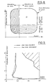
- the field of use of a wafer is defined by what is called a bag curve, which is a field in the space of pass depths, feeds and speeds, generally measured at constant speed, at l inside which the wafer fragments and controls the chip correctly.
- This domain as defined in FIG. 8, can be divided into four main sub-domains, each of these sub-domains being controlled and generated mainly by one of the parts of the brochure.
- the previously mentioned object of the present invention therefore consists in widening the domain D of the bag curve.
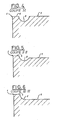
- FIGS. 1 and 2 illustrate a part of an indexable triangular cutting insert comprising a cutting edge 1 having two rectilinear portions separated by a rounded portion forming a nose or beak 2, a chip breaker 3 and a listel 4 located between the chipbreaker 3 and the cutting edge 1.
- the part before this heel 6, close to the nose is formed by the walls of the chip-breaking groove 3 (see FIG. 1) rising towards an upper surface located at the cutting edge or slightly above, then decreases towards the 'rear, that is to say towards the center of the plate, along a continuous slope.
- the heel 6 also has a lateral narrowing in the direction of the center of the pad, so as to completely release the latter to allow the evacuation and fragmentation of the chips.
- the second embodiment of the cutting insert illustrated in Figure 3 includes a heel 7 having no lateral narrowing in the direction of the center of the insert, and thus defining a chip breaker groove 8 whose upper edges are parallel.
- FIG. 7A is also illustrated in dotted lines a first variant of the heel 7 ′, the upper level of which is situated above that of the cutting edge 1.
- FIG. 7B illustrates a second variant of the heel 7 "in which the upper level of it is above the level of cutting edge 1.
- the heel 7, respectively 7 ′ and 7 ′′ has a decreasing slope in the direction of the center of the pad, so as to create a rearward depression leaving the chips the freedom to evacuate and to fragment.
- the present invention brings on the one hand an increase in the field of use of the cutting insert and on the other hand a reduction in the power absorbed by this insert during the machining work.
- the increase in the field of use can be further extended if the decreasing heel according to the present invention is combined with a listel having a variable inclination passing from a positive or zero inclination on the nose or in the vicinity thereof. zero or negative inclination along the cutting edge, as described in European patent application published EP 0 065 124 in the name of the same owner. 1
Landscapes
- Engineering & Computer Science (AREA)
- Mechanical Engineering (AREA)
- Cutting Tools, Boring Holders, And Turrets (AREA)
- Percussive Tools And Related Accessories (AREA)
- Earth Drilling (AREA)
- Turning (AREA)
- Accessories And Tools For Shearing Machines (AREA)
Claims (3)
Priority Applications (1)
| Application Number | Priority Date | Filing Date | Title |
|---|---|---|---|
| AT82103582T ATE15983T1 (de) | 1981-05-19 | 1982-04-27 | Schneidplatte zur spanabhebenden bearbeitung. |
Applications Claiming Priority (2)
| Application Number | Priority Date | Filing Date | Title |
|---|---|---|---|
| CH324781A CH642884A5 (fr) | 1981-05-19 | 1981-05-19 | Plaquette de coupe pour usinage par enlevement de copeaux. |
| CH3247/81 | 1981-05-19 |
Publications (2)
| Publication Number | Publication Date |
|---|---|
| EP0066091A1 EP0066091A1 (de) | 1982-12-08 |
| EP0066091B1 true EP0066091B1 (de) | 1985-10-09 |
Family
ID=4251835
Family Applications (1)
| Application Number | Title | Priority Date | Filing Date |
|---|---|---|---|
| EP82103582A Expired EP0066091B1 (de) | 1981-05-19 | 1982-04-27 | Schneidplatte zur spanabhebenden Bearbeitung |
Country Status (6)
| Country | Link |
|---|---|
| US (1) | US4720217A (de) |
| EP (1) | EP0066091B1 (de) |
| AT (1) | ATE15983T1 (de) |
| CH (1) | CH642884A5 (de) |
| DE (1) | DE3266762D1 (de) |
| ES (1) | ES264710Y (de) |
Families Citing this family (14)
| Publication number | Priority date | Publication date | Assignee | Title |
|---|---|---|---|---|
| JPS6112611U (ja) * | 1984-06-28 | 1986-01-24 | 住友電気工業株式会社 | スロ−アウエイチツプ |
| DE8700393U1 (de) * | 1987-01-09 | 1988-05-05 | Nederlandse Hardmetaal Fabrieken B.V., Arnhem, Nl | |
| JPH052244Y2 (de) * | 1989-08-31 | 1993-01-20 | ||
| DE4136417A1 (de) * | 1991-11-05 | 1993-05-06 | Krupp Widia Gmbh, 4300 Essen, De | Schneideinsatz |
| DE4239236C2 (de) * | 1992-11-21 | 1997-06-26 | Widia Gmbh | Schneideinsatz |
| DE4422312A1 (de) * | 1994-06-17 | 1995-12-21 | Krupp Widia Gmbh | Schneideinsatz |
| DE4437093A1 (de) * | 1994-10-17 | 1996-04-18 | Widia Gmbh | Vieleckiger Schneideinsatz |
| EP1714720B1 (de) * | 2004-01-14 | 2011-05-18 | Sumitomo Electric Hardmetal Corp. | Wendeschneidplatte |
| JP5081229B2 (ja) * | 2007-03-27 | 2012-11-28 | 京セラ株式会社 | 切削インサートおよび切削工具、並びにそれを用いた被削材の切削方法 |
| US8967920B2 (en) | 2011-09-13 | 2015-03-03 | Iscar, Ltd. | Cutting insert and chip-control arrangement therefor |
| AT14285U1 (de) * | 2013-12-02 | 2015-07-15 | Ceratizit Austria Gmbh | Schneideinsatz zur zerspanenden Drehbearbeitung |
| US10252342B2 (en) * | 2014-02-07 | 2019-04-09 | Tungaloy Corporation | Cutting insert |
| EP3189917B1 (de) * | 2014-09-05 | 2021-06-09 | Sumitomo Electric Hardmetal Corp. | Wegwerfspitze |
| CN116517475B (zh) * | 2023-06-30 | 2023-10-03 | 西南石油大学 | 一种耐磨抗碰的新型喙形齿多刀翼pdc钻头 |
Family Cites Families (11)
| Publication number | Priority date | Publication date | Assignee | Title |
|---|---|---|---|---|
| US3883748A (en) * | 1967-06-29 | 1975-05-13 | Matsushita Electric Ind Co Ltd | Phosphor for thermoluminescent type radiation dosimeter |
| JPS4815470U (de) * | 1971-06-29 | 1973-02-21 | ||
| SE349759B (de) * | 1971-10-27 | 1972-10-09 | Sandvik Ab | |
| SE380751B (sv) * | 1971-11-12 | 1975-11-17 | Seco Tools Ab | Vendsker |
| JPS5119271Y2 (de) * | 1972-02-26 | 1976-05-20 | ||
| SE361609B (de) * | 1973-01-08 | 1973-11-12 | Sandvik Ab | |
| US3947937A (en) * | 1973-11-16 | 1976-04-06 | Karl Hertel | Control groove in cutting elements for metal working tools |
| US3885281A (en) * | 1974-06-10 | 1975-05-27 | Iscar Ltd | Cutting insert with chip control |
| GB2004477B (en) * | 1977-08-05 | 1982-03-10 | Sumitomo Electric Industries | Throw away insert |
| US4214846A (en) * | 1978-09-26 | 1980-07-29 | Fansteel Inc. | Heavy duty insert |
| US4359300A (en) * | 1980-12-29 | 1982-11-16 | General Electric Co. | Cutting insert with improved chip control |
-
1981
- 1981-05-19 CH CH324781A patent/CH642884A5/fr not_active IP Right Cessation
-
1982
- 1982-04-26 ES ES1982264710U patent/ES264710Y/es not_active Expired
- 1982-04-27 EP EP82103582A patent/EP0066091B1/de not_active Expired
- 1982-04-27 AT AT82103582T patent/ATE15983T1/de active
- 1982-04-27 DE DE8282103582T patent/DE3266762D1/de not_active Expired
- 1982-05-04 US US06/374,738 patent/US4720217A/en not_active Expired - Lifetime
Also Published As
| Publication number | Publication date |
|---|---|
| ATE15983T1 (de) | 1985-10-15 |
| CH642884A5 (fr) | 1984-05-15 |
| DE3266762D1 (en) | 1985-11-14 |
| EP0066091A1 (de) | 1982-12-08 |
| ES264710U (es) | 1982-11-16 |
| ES264710Y (es) | 1983-05-16 |
| US4720217A (en) | 1988-01-19 |
Similar Documents
| Publication | Publication Date | Title |
|---|---|---|
| EP0066091B1 (de) | Schneidplatte zur spanabhebenden Bearbeitung | |
| US4685844A (en) | Cutting insert | |
| EP0800429B1 (de) | Schneideinsatz mit einem spanbrecher für dünne späne | |
| SK155798A3 (en) | A cutting insert with a rounded corner | |
| LU83605A1 (fr) | Piece rapportee de coupe | |
| US6224300B1 (en) | Cutting insert for shaping by chipping | |
| US5249894A (en) | High sheer, ultra light duty insert | |
| CA2204732A1 (en) | Cutting insert for machining workpieces and simultaneously removing cuttings | |
| EP2434917B1 (de) | Optimierung für einen schuh, insbesondere für einen sportschuh | |
| US5193948A (en) | Chip control inserts with diamond segments | |
| AU5578499A (en) | Flat bottom tool | |
| FR2624414A1 (fr) | Plaquette de coupe a aretes de coupe surelevees | |
| EP1334653B1 (de) | Baumscheren | |
| EP0065124B2 (de) | Schneidplatte zur spanabhebenden Bearbeitung | |
| LU81889A1 (fr) | Piece rapportee de coupe | |
| FR2690892A1 (fr) | Navire brise-glace. | |
| US6341924B1 (en) | Insert for the cutting of grooves | |
| JP4688378B2 (ja) | ドリル用スローアウェイチップ | |
| CA1176827A (en) | Cutting insert | |
| CH631923A5 (fr) | Pneumatique. | |
| FR2481168A3 (fr) | Support pour plaquettes de coupe rapportees, inversables, et plaquettes pour ledit support | |
| JPH08118135A (ja) | 回転切削工具用のスローアウェイチップ | |
| FR2571330A1 (fr) | Coque de navire perfectionnee | |
| JP2585715Y2 (ja) | スローアウェイチップ | |
| EP0730925B1 (de) | Hochgeschwindigkeitsschneideinsatz mit Spanbrecher |
Legal Events
| Date | Code | Title | Description |
|---|---|---|---|
| PUAI | Public reference made under article 153(3) epc to a published international application that has entered the european phase |
Free format text: ORIGINAL CODE: 0009012 |
|
| AK | Designated contracting states |
Designated state(s): AT BE DE FR GB IT LU NL SE |
|
| 17P | Request for examination filed |
Effective date: 19830527 |
|
| ITF | It: translation for a ep patent filed |
Owner name: CON LOR S.R.L. |
|
| GRAA | (expected) grant |
Free format text: ORIGINAL CODE: 0009210 |
|
| AK | Designated contracting states |
Designated state(s): AT BE DE FR GB IT LU NL SE |
|
| REF | Corresponds to: |
Ref document number: 15983 Country of ref document: AT Date of ref document: 19851015 Kind code of ref document: T |
|
| REF | Corresponds to: |
Ref document number: 3266762 Country of ref document: DE Date of ref document: 19851114 |
|
| PLBE | No opposition filed within time limit |
Free format text: ORIGINAL CODE: 0009261 |
|
| STAA | Information on the status of an ep patent application or granted ep patent |
Free format text: STATUS: NO OPPOSITION FILED WITHIN TIME LIMIT |
|
| 26N | No opposition filed | ||
| ITTA | It: last paid annual fee | ||
| PGFP | Annual fee paid to national office [announced via postgrant information from national office to epo] |
Ref country code: LU Payment date: 19930324 Year of fee payment: 12 |
|
| PGFP | Annual fee paid to national office [announced via postgrant information from national office to epo] |
Ref country code: BE Payment date: 19930329 Year of fee payment: 12 |
|
| PGFP | Annual fee paid to national office [announced via postgrant information from national office to epo] |
Ref country code: SE Payment date: 19930330 Year of fee payment: 12 |
|
| PGFP | Annual fee paid to national office [announced via postgrant information from national office to epo] |
Ref country code: GB Payment date: 19930426 Year of fee payment: 12 |
|
| PGFP | Annual fee paid to national office [announced via postgrant information from national office to epo] |
Ref country code: AT Payment date: 19930427 Year of fee payment: 12 |
|
| PGFP | Annual fee paid to national office [announced via postgrant information from national office to epo] |
Ref country code: NL Payment date: 19930430 Year of fee payment: 12 Ref country code: FR Payment date: 19930430 Year of fee payment: 12 |
|
| PGFP | Annual fee paid to national office [announced via postgrant information from national office to epo] |
Ref country code: DE Payment date: 19930629 Year of fee payment: 12 |
|
| EPTA | Lu: last paid annual fee | ||
| PG25 | Lapsed in a contracting state [announced via postgrant information from national office to epo] |
Ref country code: LU Free format text: LAPSE BECAUSE OF NON-PAYMENT OF DUE FEES Effective date: 19940427 Ref country code: GB Effective date: 19940427 Ref country code: AT Effective date: 19940427 |
|
| PG25 | Lapsed in a contracting state [announced via postgrant information from national office to epo] |
Ref country code: SE Effective date: 19940428 |
|
| PG25 | Lapsed in a contracting state [announced via postgrant information from national office to epo] |
Ref country code: BE Effective date: 19940430 |
|
| BERE | Be: lapsed |
Owner name: STELLRAM S.A. Effective date: 19940430 |
|
| PG25 | Lapsed in a contracting state [announced via postgrant information from national office to epo] |
Ref country code: NL Effective date: 19941101 |
|
| NLV4 | Nl: lapsed or anulled due to non-payment of the annual fee | ||
| GBPC | Gb: european patent ceased through non-payment of renewal fee |
Effective date: 19940427 |
|
| PG25 | Lapsed in a contracting state [announced via postgrant information from national office to epo] |
Ref country code: FR Effective date: 19941229 |
|
| PG25 | Lapsed in a contracting state [announced via postgrant information from national office to epo] |
Ref country code: DE Effective date: 19950103 |
|
| EUG | Se: european patent has lapsed |
Ref document number: 82103582.1 Effective date: 19941110 |
|
| REG | Reference to a national code |
Ref country code: FR Ref legal event code: ST |