EP0065124B2 - Schneidplatte zur spanabhebenden Bearbeitung - Google Patents
Schneidplatte zur spanabhebenden Bearbeitung Download PDFInfo
- Publication number
- EP0065124B2 EP0065124B2 EP82103476A EP82103476A EP0065124B2 EP 0065124 B2 EP0065124 B2 EP 0065124B2 EP 82103476 A EP82103476 A EP 82103476A EP 82103476 A EP82103476 A EP 82103476A EP 0065124 B2 EP0065124 B2 EP 0065124B2
- Authority
- EP
- European Patent Office
- Prior art keywords
- cutting
- cutting edge
- angle
- nose
- insert
- Prior art date
- Legal status (The legal status is an assumption and is not a legal conclusion. Google has not performed a legal analysis and makes no representation as to the accuracy of the status listed.)
- Expired - Lifetime
Links
- 239000002184 metal Substances 0.000 title description 2
- 238000003754 machining Methods 0.000 claims abstract description 6
- 230000002093 peripheral effect Effects 0.000 claims description 2
- 238000013467 fragmentation Methods 0.000 description 4
- 238000006062 fragmentation reaction Methods 0.000 description 4
- 230000007704 transition Effects 0.000 description 3
- 230000003247 decreasing effect Effects 0.000 description 2
- 108020001568 subdomains Proteins 0.000 description 2
- QNRATNLHPGXHMA-XZHTYLCXSA-N (r)-(6-ethoxyquinolin-4-yl)-[(2s,4s,5r)-5-ethyl-1-azabicyclo[2.2.2]octan-2-yl]methanol;hydrochloride Chemical compound Cl.C([C@H]([C@H](C1)CC)C2)CN1[C@@H]2[C@H](O)C1=CC=NC2=CC=C(OCC)C=C21 QNRATNLHPGXHMA-XZHTYLCXSA-N 0.000 description 1
- 210000003323 beak Anatomy 0.000 description 1
- 238000005265 energy consumption Methods 0.000 description 1
- 230000002349 favourable effect Effects 0.000 description 1
- 239000012634 fragment Substances 0.000 description 1
- 239000000463 material Substances 0.000 description 1
- 230000002787 reinforcement Effects 0.000 description 1
Images


Classifications
-
- B—PERFORMING OPERATIONS; TRANSPORTING
- B23—MACHINE TOOLS; METAL-WORKING NOT OTHERWISE PROVIDED FOR
- B23B—TURNING; BORING
- B23B27/00—Tools for turning or boring machines; Tools of a similar kind in general; Accessories therefor
- B23B27/14—Cutting tools of which the bits or tips or cutting inserts are of special material
- B23B27/141—Specially shaped plate-like cutting inserts, i.e. length greater or equal to width, width greater than or equal to thickness
- B23B27/143—Specially shaped plate-like cutting inserts, i.e. length greater or equal to width, width greater than or equal to thickness characterised by having chip-breakers
Definitions
- the present invention relates to cutting inserts for machining by chip removal comprising at least one cutting edge, a nose and a chip breaker.
- These cutting inserts are preferably indexable and may have a square, triangular, rhombic or other shape.
- chip breakers generally executed in the form of grooves along the cutting edges, in order to favor the control of said chips.
- this chipbreaker can be of variable width and comprise in its cross section one or more parts, straight or curved, variable according to their position along the cutting edge.
- the object of this invention is to provide a cutting insert of the aforementioned type which has the optimum functional characteristics in the widest possible range of use, i.e. depths, feeds, speeds and the material, during machining.
- the object of the present invention aims to achieve the aforementioned object, consists of a cutting insert for machining by chip removal comprising at least one cutting edge, a nose and a chip breaker, as well as a peripheral strip, between the cutting edge and the chip breaker, characterized in that the strip is of constant width and that it progressively passes from a positive cutting angle on the nose and / or near it at a zero or negative cutting angle along the cutting edge, so that said strip has a twisted configuration.
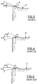
- Figure 1 is a partial perspective view of an embodiment of a cutting insert according to the invention.
- FIG. 2 is a top view of the embodiment of FIG. 1.
- Figures 3,4 and 5 are sectional views along lines I-I, II-II and III-III, respectively of Figure 2.
- Figure 6 shows a theoretical bag curve
- FIG. 7 represents two superimposed bag curves obtained respectively for a cutting insert according to the invention and for a standard insert.
- the field of use of a wafer is defined by what is called a bag curve, which is a field in the space of pass depths, feeds and speeds, generally measured at constant speed, at l inside which the wafer fragments and controls the chip correctly.
- This domain as defined in FIG. 6, can be divided into four main sub-domains, each of these sub-domains being controlled and generated mainly by one of the parts of the brochure. We can therefore establish a one-to-one relationship between the field of depths and advances and the geometric space of the plate. The best insert geometry will be that which will define the widest space in the area of pass depths and feeds.
- the illustrated cutting insert portion includes a cutting edge 1 having straight portions and a rounded portion forming a beak or nose 2, as well as a chip breaker 3 formed along of the cutting edge 1 by the lateral slopes of a central depression 4. Between the chipbreakers 3 and the cutting edge 1 is located a strip 5, here of constant width around the periphery of the insert.
- the zones A, B, C and D correspond to the respective zones defined by the bag curve of FIG. 6.
- the strip 5 has a positive cutting angle on the nose 2 of the wafer and a transition zone T where the cutting angle progressively changes to a negative value exhibited by l cutting edge 1.
- the passage from a positive angle to a negative angle thus gives the listel 5 a twisted appearance.
- the change in cutting angle is also illustrated in FIGS. 3 to 5 representing cuts at the level of the nose 2, of the beginning of the cutting edge 1 and of the middle thereof, respectively.
- the second cutting angle Y 21 in the area A is smaller than the second cutting angle Y 22 in the area D, or possibly equal to this.
- zones B and C having equal angles Y11, Y12 and Y 13 , either negative or zero and zones A and D having angles Y 21 , Y 22 and Y 23 are equal, or of decreasing values from zone A.
- the value of the positive angle can be between 0 and 10 °.
- the area B should preferably be characterized by a fairly large angle Y 11 , this due to the inclination of the insert on the tool holder.
- the domain C must have zero or negative angles Y 12 and Y 13 while Y 11 is positive.
- the transition between Y 11 and Y 12 takes place continuously.
- angles Y 22 and Y 23 can be either equal or Y 23 smaller than Y 22 .
- the angle Y 22 must be equal to or greater than the angle Y 21 of the domain A. This is always specified as a function of the relationships between each of the domains and of their representation of fragmentation in the space of pass depths and advances.
- the characteristics according to the invention can be superimposed on an angle of inclination of the cutting edge, in order to compensate for the inclination of the plate on the tool holder; the value of this angle can be between 0 and 10 °, the nose itself remaining at 0 °.
- FIG. 7 representing the bagged curves obtained one by one with a standard insert and on the other hand with a insert according to l 'invention.
- the external area between the two curves constitutes the portion of the enlarged domain.
- the cutting insert according to the invention can also be provided with a heel decreasing towards the center of the insert, as described in the European patent application published EP 0 066 091, in the name of the same owner, in order further increase the domain D of the bag curve.
Landscapes
- Engineering & Computer Science (AREA)
- Mechanical Engineering (AREA)
- Milling Processes (AREA)
- Cutting Tools, Boring Holders, And Turrets (AREA)
- Accessories And Tools For Shearing Machines (AREA)
- Turning (AREA)
Claims (3)
Priority Applications (1)
| Application Number | Priority Date | Filing Date | Title |
|---|---|---|---|
| AT82103476T ATE13830T1 (de) | 1981-05-19 | 1982-04-24 | Schneidplatte zur spanabhebenden bearbeitung. |
Applications Claiming Priority (2)
| Application Number | Priority Date | Filing Date | Title |
|---|---|---|---|
| CH324681A CH642883A5 (fr) | 1981-05-19 | 1981-05-19 | Plaquette de coupe pour usinage par enlevement de copeaux. |
| CH3246/81 | 1981-05-19 |
Publications (3)
| Publication Number | Publication Date |
|---|---|
| EP0065124A1 EP0065124A1 (de) | 1982-11-24 |
| EP0065124B1 EP0065124B1 (de) | 1985-06-19 |
| EP0065124B2 true EP0065124B2 (de) | 1992-10-07 |
Family
ID=4251812
Family Applications (1)
| Application Number | Title | Priority Date | Filing Date |
|---|---|---|---|
| EP82103476A Expired - Lifetime EP0065124B2 (de) | 1981-05-19 | 1982-04-24 | Schneidplatte zur spanabhebenden Bearbeitung |
Country Status (5)
| Country | Link |
|---|---|
| EP (1) | EP0065124B2 (de) |
| AT (1) | ATE13830T1 (de) |
| CH (1) | CH642883A5 (de) |
| DE (1) | DE3264250D1 (de) |
| ES (1) | ES264709Y (de) |
Families Citing this family (6)
| Publication number | Priority date | Publication date | Assignee | Title |
|---|---|---|---|---|
| US5230591A (en) * | 1992-08-10 | 1993-07-27 | Gte Valenite Corporation | Insert for light feed, light depth of cut |
| US5725334A (en) * | 1993-03-29 | 1998-03-10 | Widia Gmbh | Cutting insert |
| US5388932A (en) * | 1993-09-13 | 1995-02-14 | Kennametal Inc. | Cutting insert for a milling cutter |
| US5876160A (en) * | 1996-08-21 | 1999-03-02 | Ingersoll Cutting Tool Company | Milling with insert having cutting-edge land of width increasing with depth of cut |
| AT406241B (de) † | 1998-03-31 | 2000-03-27 | Boehlerit Gmbh & Co Kg | Schneideinsatz für zerspanungswerkzeuge |
| SE530153C2 (sv) * | 2005-02-22 | 2008-03-11 | Seco Tools Ab | Skär för svarvning med ett perifert land av konstant bredd |
Family Cites Families (2)
| Publication number | Priority date | Publication date | Assignee | Title |
|---|---|---|---|---|
| SE349758B (de) * | 1971-10-27 | 1972-10-09 | Sandvik Ab | |
| SE361609B (de) * | 1973-01-08 | 1973-11-12 | Sandvik Ab |
-
1981
- 1981-05-19 CH CH324681A patent/CH642883A5/fr not_active IP Right Cessation
-
1982
- 1982-04-24 DE DE8282103476T patent/DE3264250D1/de not_active Expired
- 1982-04-24 EP EP82103476A patent/EP0065124B2/de not_active Expired - Lifetime
- 1982-04-24 AT AT82103476T patent/ATE13830T1/de not_active IP Right Cessation
- 1982-04-26 ES ES1982264709U patent/ES264709Y/es not_active Expired
Also Published As
| Publication number | Publication date |
|---|---|
| ES264709Y (es) | 1983-05-16 |
| CH642883A5 (fr) | 1984-05-15 |
| DE3264250D1 (en) | 1985-07-25 |
| ES264709U (es) | 1982-11-16 |
| ATE13830T1 (de) | 1985-07-15 |
| EP0065124A1 (de) | 1982-11-24 |
| EP0065124B1 (de) | 1985-06-19 |
Similar Documents
| Publication | Publication Date | Title |
|---|---|---|
| US5791833A (en) | Cutting insert having a chipbreaker for thin chips | |
| EP0577011B1 (de) | Schneideinsatz und Fräser | |
| US5544984A (en) | Cutting insert with twisted chip surface | |
| JP3755832B2 (ja) | 丸コーナーを有する切削インサート | |
| US5676495A (en) | Cutting insert | |
| US4685844A (en) | Cutting insert | |
| US4671710A (en) | Drill bit | |
| CA2026582A1 (en) | Drill | |
| US5249894A (en) | High sheer, ultra light duty insert | |
| EP0065124B2 (de) | Schneidplatte zur spanabhebenden Bearbeitung | |
| EP0066091B1 (de) | Schneidplatte zur spanabhebenden Bearbeitung | |
| JPH08505815A (ja) | 捩れ逃げ面を備えた切削インサート | |
| JP5056215B2 (ja) | 切削インサート | |
| CN1108216C (zh) | 用于槽的切削的刀片 | |
| JPS6334003A (ja) | スロ−アウエイチツプ | |
| JPH0747245B2 (ja) | 二枚刃ガンドリル | |
| JP2585715Y2 (ja) | スローアウェイチップ | |
| JP3366751B2 (ja) | スローアウェイチップ | |
| JPH0155924B2 (de) | ||
| JPS6012645Y2 (ja) | スロ−アウエイチツプ | |
| JPH0463613A (ja) | スローアウエイチツプ | |
| JPS6246491Y2 (de) | ||
| JPS5833051B2 (ja) | 丸鋸 | |
| CN204277044U (zh) | 负型铣削刀片 | |
| JP3201036B2 (ja) | ポジティブスローアウェイチップ |
Legal Events
| Date | Code | Title | Description |
|---|---|---|---|
| PUAI | Public reference made under article 153(3) epc to a published international application that has entered the european phase |
Free format text: ORIGINAL CODE: 0009012 |
|
| AK | Designated contracting states |
Designated state(s): AT BE DE FR GB IT LU NL SE |
|
| 17P | Request for examination filed |
Effective date: 19830411 |
|
| ITF | It: translation for a ep patent filed | ||
| GRAA | (expected) grant |
Free format text: ORIGINAL CODE: 0009210 |
|
| AK | Designated contracting states |
Designated state(s): AT BE DE FR GB IT LU NL SE |
|
| REF | Corresponds to: |
Ref document number: 13830 Country of ref document: AT Date of ref document: 19850715 Kind code of ref document: T |
|
| REF | Corresponds to: |
Ref document number: 3264250 Country of ref document: DE Date of ref document: 19850725 |
|
| PLBI | Opposition filed |
Free format text: ORIGINAL CODE: 0009260 |
|
| 26 | Opposition filed |
Opponent name: FELDMUEHLE AKTIENGESELLSCHAFT, DUESSELDORF Effective date: 19860314 Opponent name: FRIED. KRUPP GMBH Effective date: 19860312 |
|
| NLR1 | Nl: opposition has been filed with the epo |
Opponent name: FELDMUEHLE AKTIENGESELLSCHAFT Opponent name: FRIED. KRUPP GMBH |
|
| PLAB | Opposition data, opponent's data or that of the opponent's representative modified |
Free format text: ORIGINAL CODE: 0009299OPPO |
|
| R26 | Opposition filed (corrected) |
Opponent name: KRUPP WIDIA GMBH * 860314 FELDMUEHLE AKTIENGESELLS Effective date: 19860312 |
|
| NLXE | Nl: other communications concerning ep-patents (part 3 heading xe) |
Free format text: IN PAT.BUL.12/86,PAGE 1487:CORR.:KRUPP WIDIA GMBH |
|
| PLAB | Opposition data, opponent's data or that of the opponent's representative modified |
Free format text: ORIGINAL CODE: 0009299OPPO |
|
| R26 | Opposition filed (corrected) |
Opponent name: KRUPP WIDIA GMBH * 860314 FELDMUEHLE AKTIENGESELLS Effective date: 19860312 |
|
| ITTA | It: last paid annual fee | ||
| PUAH | Patent maintained in amended form |
Free format text: ORIGINAL CODE: 0009272 |
|
| STAA | Information on the status of an ep patent application or granted ep patent |
Free format text: STATUS: PATENT MAINTAINED AS AMENDED |
|
| 27A | Patent maintained in amended form |
Effective date: 19921007 |
|
| AK | Designated contracting states |
Kind code of ref document: B2 Designated state(s): AT BE DE FR GB IT LU NL SE |
|
| NLR2 | Nl: decision of opposition | ||
| ITF | It: translation for a ep patent filed | ||
| NLR3 | Nl: receipt of modified translations in the netherlands language after an opposition procedure | ||
| EPTA | Lu: last paid annual fee | ||
| EAL | Se: european patent in force in sweden |
Ref document number: 82103476.6 |
|
| PGFP | Annual fee paid to national office [announced via postgrant information from national office to epo] |
Ref country code: SE Payment date: 19990322 Year of fee payment: 18 Ref country code: BE Payment date: 19990322 Year of fee payment: 18 |
|
| PGFP | Annual fee paid to national office [announced via postgrant information from national office to epo] |
Ref country code: AT Payment date: 19990414 Year of fee payment: 18 |
|
| PGFP | Annual fee paid to national office [announced via postgrant information from national office to epo] |
Ref country code: LU Payment date: 19990422 Year of fee payment: 18 |
|
| PGFP | Annual fee paid to national office [announced via postgrant information from national office to epo] |
Ref country code: GB Payment date: 19990423 Year of fee payment: 18 Ref country code: FR Payment date: 19990423 Year of fee payment: 18 |
|
| PGFP | Annual fee paid to national office [announced via postgrant information from national office to epo] |
Ref country code: NL Payment date: 19990429 Year of fee payment: 18 |
|
| PGFP | Annual fee paid to national office [announced via postgrant information from national office to epo] |
Ref country code: DE Payment date: 19990629 Year of fee payment: 18 |
|
| PG25 | Lapsed in a contracting state [announced via postgrant information from national office to epo] |
Ref country code: LU Free format text: LAPSE BECAUSE OF NON-PAYMENT OF DUE FEES Effective date: 20000424 Ref country code: GB Free format text: LAPSE BECAUSE OF NON-PAYMENT OF DUE FEES Effective date: 20000424 Ref country code: AT Free format text: LAPSE BECAUSE OF NON-PAYMENT OF DUE FEES Effective date: 20000424 |
|
| PG25 | Lapsed in a contracting state [announced via postgrant information from national office to epo] |
Ref country code: SE Free format text: LAPSE BECAUSE OF NON-PAYMENT OF DUE FEES Effective date: 20000425 |
|
| PG25 | Lapsed in a contracting state [announced via postgrant information from national office to epo] |
Ref country code: BE Free format text: LAPSE BECAUSE OF NON-PAYMENT OF DUE FEES Effective date: 20000430 |
|
| BERE | Be: lapsed |
Owner name: STELLRAM S.A. Effective date: 20000430 |
|
| PG25 | Lapsed in a contracting state [announced via postgrant information from national office to epo] |
Ref country code: NL Free format text: LAPSE BECAUSE OF NON-PAYMENT OF DUE FEES Effective date: 20001101 |
|
| EUG | Se: european patent has lapsed |
Ref document number: 82103476.6 |
|
| GBPC | Gb: european patent ceased through non-payment of renewal fee |
Effective date: 20000424 |
|
| PG25 | Lapsed in a contracting state [announced via postgrant information from national office to epo] |
Ref country code: FR Free format text: LAPSE BECAUSE OF NON-PAYMENT OF DUE FEES Effective date: 20001229 |
|
| NLV4 | Nl: lapsed or anulled due to non-payment of the annual fee |
Effective date: 20001101 |
|
| PG25 | Lapsed in a contracting state [announced via postgrant information from national office to epo] |
Ref country code: DE Free format text: LAPSE BECAUSE OF NON-PAYMENT OF DUE FEES Effective date: 20010201 |
|
| REG | Reference to a national code |
Ref country code: FR Ref legal event code: ST |
|
| APAH | Appeal reference modified |
Free format text: ORIGINAL CODE: EPIDOSCREFNO |