EP0065935A2 - Improvements to cartridge-type rolling stands and cartridge-type rolling stands thus improved - Google Patents
Improvements to cartridge-type rolling stands and cartridge-type rolling stands thus improved Download PDFInfo
- Publication number
- EP0065935A2 EP0065935A2 EP82830107A EP82830107A EP0065935A2 EP 0065935 A2 EP0065935 A2 EP 0065935A2 EP 82830107 A EP82830107 A EP 82830107A EP 82830107 A EP82830107 A EP 82830107A EP 0065935 A2 EP0065935 A2 EP 0065935A2
- Authority
- EP
- European Patent Office
- Prior art keywords
- cartridge
- rolling stands
- rolls
- type rolling
- fact
- Prior art date
- Legal status (The legal status is an assumption and is not a legal conclusion. Google has not performed a legal analysis and makes no representation as to the accuracy of the status listed.)
- Withdrawn
Links
- 238000005096 rolling process Methods 0.000 title claims abstract description 63
- 230000005540 biological transmission Effects 0.000 claims description 9
- 238000004873 anchoring Methods 0.000 claims description 6
- 230000001105 regulatory effect Effects 0.000 claims description 6
- 230000033001 locomotion Effects 0.000 claims description 4
- 125000006850 spacer group Chemical group 0.000 claims description 4
- 239000012530 fluid Substances 0.000 description 3
- 229910000831 Steel Inorganic materials 0.000 description 1
- 230000009471 action Effects 0.000 description 1
- 230000008901 benefit Effects 0.000 description 1
- 230000008878 coupling Effects 0.000 description 1
- 238000010168 coupling process Methods 0.000 description 1
- 238000005859 coupling reaction Methods 0.000 description 1
- 230000008030 elimination Effects 0.000 description 1
- 238000003379 elimination reaction Methods 0.000 description 1
- 238000003780 insertion Methods 0.000 description 1
- 230000037431 insertion Effects 0.000 description 1
- 238000012423 maintenance Methods 0.000 description 1
- 230000007246 mechanism Effects 0.000 description 1
- 239000010959 steel Substances 0.000 description 1
Images

Classifications
-
- B—PERFORMING OPERATIONS; TRANSPORTING
- B21—MECHANICAL METAL-WORKING WITHOUT ESSENTIALLY REMOVING MATERIAL; PUNCHING METAL
- B21B—ROLLING OF METAL
- B21B31/00—Rolling stand structures; Mounting, adjusting, or interchanging rolls, roll mountings, or stand frames
- B21B31/02—Rolling stand frames or housings; Roll mountings ; Roll chocks
- B21B31/04—Rolling stand frames or housings; Roll mountings ; Roll chocks with tie rods in frameless stands, e.g. prestressed tie rods
-
- B—PERFORMING OPERATIONS; TRANSPORTING
- B21—MECHANICAL METAL-WORKING WITHOUT ESSENTIALLY REMOVING MATERIAL; PUNCHING METAL
- B21B—ROLLING OF METAL
- B21B31/00—Rolling stand structures; Mounting, adjusting, or interchanging rolls, roll mountings, or stand frames
- B21B31/02—Rolling stand frames or housings; Roll mountings ; Roll chocks
- B21B31/06—Fastening stands or frames to foundation, e.g. to the sole plate
-
- B—PERFORMING OPERATIONS; TRANSPORTING
- B21—MECHANICAL METAL-WORKING WITHOUT ESSENTIALLY REMOVING MATERIAL; PUNCHING METAL
- B21B—ROLLING OF METAL
- B21B2203/00—Auxiliary arrangements, devices or methods in combination with rolling mills or rolling methods
- B21B2203/36—Spacers
-
- B—PERFORMING OPERATIONS; TRANSPORTING
- B21—MECHANICAL METAL-WORKING WITHOUT ESSENTIALLY REMOVING MATERIAL; PUNCHING METAL
- B21B—ROLLING OF METAL
- B21B31/00—Rolling stand structures; Mounting, adjusting, or interchanging rolls, roll mountings, or stand frames
- B21B31/16—Adjusting or positioning rolls
- B21B31/18—Adjusting or positioning rolls by moving rolls axially
Definitions
- This invention concerns improvements to cartridge-type rolling stands and also cartridge-type rolling stands thus .improved.
- said improvements are adopted preferably on two-roll (two-high) rolling stands, whether horizontal or upright, with a possibly adjustable rolling axis.
- the invention concerns particularly rolling stands which .may possibly be movable and which consist advantageously of . .fitted parts that can be dismantled and replaced speedily.
- the improvements of the invention envisage the elimination of the uprights which contain the housings and which are normally comprised in known types of rolling stands, and the replacement thereof with suitable stay rods which pass at .least partially through said housings.
- stay rods can be made of best-quality steel, which will enable them to withstand heavy loads with relatively modest sections and will lead to a further lessening of the weight and overall size of the stand.
- the improvements of the invention envisage that the distance between the axes, or between the centres, of .the rolls will be regulated by an appropriate application of. .shims below the housings of the lower roll and by an adjust-- .ment of the position of the upper roll with screw pressing . means
- Said improvements also enable the adjustment of said .distance between centres to be obtained with screw pressing . .means acting against the housings of the lower and upper rolls, but the interposition of suitable spring-type and/or hydrau- .lic spacer means between said housings is required to balance the rolls.
- Said improvements envisage in particular the use of clamping systems which ensure a strong anchorage and easy handling when clamping and unclamping the stand.
- the advantage is obvious which these improvements lead to in making possible the perfect fitting-out of the stands in the. appropriate shop instead of in the rolling line, and there is a clear gain in time and quality of workmanship
- the invention is therefore displayed with improvements to cartridge-type rolling stands equipped with two rolls lying alongside each other and disposed with their axis horizontal or upright, whereby said rolls are of a replaceable type and are complete with housings, and whereby means to position the rolls axially are comprised, said improvements being characterized by including one or more of the following:
- the invention is also embodied with cartridge-type rolling stands equipped with two rolls lying side by side and disposed with their axis horizontal or upright, whereby said rolls are of a replaceable type and are complete with housings, and whereby means to position the rolls axially are comprised, said stands being characterized by the fact that they adopt . at least one of said improvements.
- the cartridge-type rolling stand 20 shown in Figs.1 and 2 comprises two rolls 21-121 with horizontal axes, parallel to each other and equipped with frontal supporting . housings 22.
- said rolling stand 20 consists of a base carrying structure 25 comprising lengthwise bars 26 and cross- . wise bars 27 which are rigidly and solidly fixed to each other.
- Stay rods 24 are installed through said crosswise bars. 27 and are clamped axially to said bars 27; moreover, the heads 28 of the rolling stand 20 are installed above said .stay rods 24.
- the assemblage thus formed is reciprocally fastened and serves to guide the housings 22 which are installed so as to be able to slide on the stay rods 24 and between the bar 27 and head 28.
- the stay rods 24 have their ends equipped with contrast and containing means 29
- the lower contrast and containment means I29 consist of an end which is solidly fixed to the stay rod.
- the upper containment means 229 consist of a lock nut 30 which can be screwed onto the end of said stay rod 24, and of a ring nut 31 which can be screwed onto said lock nut. 30.
- Some fluid under pressure is then introduced into one . or more jacks 32 fitted into the lock nut 30, so as to act on the piston 33 located within said jacks 32.
- a rigid supporting structure 87 is formed which consists of the upright stay rods 24, upper head 28 and lower crosswise bar 27, all of which are fastened solidly to each other.
- the ring nut 31 can be tightened up at leisu- . re until it presses against the head 28, and after that the . . fluid under pressure in the jacks 32 can be withdrawn so that .the ring nut 3I itself now acts as the clamping element.
- Adjustment of the distance between the axes (distance between centres) of the rolls 21-121 is obtained with suit- .able means 34 to adjust the distance between centres of the . rolls 21-121 and with suitable means 35 to balance the upper roll 21.
- said means 34 to adjust the distance between centres consist of spacer means or distance pieces 36 and of adjustable screw pressing means 37 which are contained at least, partially within a box-wise cross piece 48.
- Said spacer means 36 are located in the lower part of the rolling stand 20 between the crosswise bars 27 and lower housings 22 so as to position the lower roll I2I in relation to a pre-set rolling axis.
- the adjustable screw means 37 cooperate with the head 28, xhich comprises a through female thread 38 machined cent- .rally and vertically through said head 28.
- a pressing bolt element 39 is screwed into the female thread 38 so as to press centrally against the upper housing 22.
- Said pressure is balanced by a force of contrasting .vertical expansion exerted by the balancing means 35 located, .between the lower I22 and upper 22 housings near the stay rods 24, as shown in Fig.4.
- Said balancing means 35 consist, in our example, of expansion springs 40 which are located in suitable chambers .4I machined in the upper part of the housing 122 and which .act vertically against the pistons 88 solidly fixed to the .housings 22.
- the upper roll 21 can .be balanced by employing hydraulic jacks 41.
- Said regulation of said screw means 37 is obtained, in .particular, by acting on the suitably shaped upper part of .the pressing bolt element 39 by means of a key of the torque- multiplier type, for instance.
- a graduated ring 44 is solidly connected, or can be so- .lidly connected, to the pressing bolt element 39 by key means .43 and cooperates axially with a shaft 45.
- Said shaft 45 is fitted on the outside of and coaxially with the element 39 and bears circumferentially on its own outside a toothed crown 46 able to mesh with a transmission . chain 47.
- this operation is carried out by reducing the gap between the rolls 21-121 and reading (checking) .the size reached on the rotatable graduated ring 44 and indi7 .cated by a stationary pointer (not shown here).
- the stationary pointer indicates "nought" on the scale .of the graduated ring 44.
- each screw .means 37 by unfastening and raising the graduated ring 44 so. that the latter does not cooperate with the shaft 45 and, .substantially, so that motion is not transmitted to the chain 47.
- the rigidity of the rolling stand 20 is maintained in .its upper part by the box-wise cross piece 48, which connects the pair of heads 28 and incorporates the adjustable screw pressing means 37 at least partially.
- Fig.I shows some equipment-carrying bar means 49,which. are anchored to the stand 20 and positioned vertically so as. to be able to cooperate with the rolling axis of said stand . 20.
- Said screw stays 50 are solidly anchored (54) at one . end to said means 49 and cooperate at their other end, by means of their upper threaded end 5I, with through holes 52 machined in the side of the heads 28 and with suitable traction and clamping means 53 which in this case consist of'a nut and lock nut.
- said equipment- . carrying bar means 49 also act as lateral contrast and con- . tainment means for the housings 22-122.
- Fig.I also shows two different kinds of anchorage of the rolling stand 20 to the floor 55; one kind alone or both. kinds can be employed for the same rolling stand 20.
- anchorage means 56 can be used which are shown on the right in Fig.I and comprise bolts 57 for anchoring the stand 20 to the floor 55.
- Figs.2 and 3 show axial positioning means 62 which serve to set the mutualaxial positions of the grooves (not shown) of the cylinders 21-121.
- Said positioning means 62 can cooperate at least with . one cylinder 21-121, the other cylinder 121-21 being possibly fixed.
- Said positioning means 62 consist of a fixed support 63 connected to the housings 22 and/or I22 and bearing axially . a threaded pin 65, which is welded or otherwise connected at. one of its lengthwise ends 64 to a flange 66.
- Said flange 66 cooperates with one end 67 of the roll . 21 or 121, the other end of the roll 21 or 121 being able to. slide axially.
- the axial clamping of said positioning means 62 is brought about by tightening axially, on the fixed support 63, .two nuts 68-168 cooperating with the threaded part of the pin 65.
- Said tightening can be performed with keys 69-169 of a known type, which are possibly equipped with a mechanism to invert the direction of actuation.
- Fig.3 also shows an element or pin 79 which can be screw- .ed and which can clamp the stay rod 24 within the hole 23 by. means of a contrast notch 80.
- Fig.4 shows an outer front view of the stand 20 we have just described.
- Said stand 20 has a rolling axis which can possibly be . regulated during the course of successive rolling operations. carried out with the same pair of rolls 21-121.
- Fig.5 shows a variant of the rolling stand wherein the rolling axis is fixed. Said fixed rolling axis is obtained in particular, by employing a pair of adjustable screw pressing means 37-137 for each pair of housings 22 cooperating with the same end of the rolls 21-121.
- Said adjustable screw pressing means 37-137 are located in the upper and lower parts of the stand 20 so as to cooperate with the shoulders 28 and crosswise bars 27 to press at . the same time against the upper and lower housings 22 respectively.
- Said transmission system 70 comprises chain means 71-171 able to cooperate with the respective pressing means 37 and . to mesh with the gear wheels 73-173 at the ends of an upright shaft or pin 72 linking said chain means 71-171
- Figs.6-7-8 give a side view of some variants embodying. the means 56 anchoring the rolling stand 20 to the floor 55..
- Fig.6 shows means 56 for anchoring the . stand 20 centrally by insertion of suitably shaped protrusions 74, comprised on the base structure 25 of the stand 20, within brackets 75 anchored to the floor 55.
- FIG.8 The embodiment shown in the orthogonal projection of Fig.8 comprises hydraulic-bracket anchorage means 90 the working of which is the same as that described for the means 29..
- Figs.9-IO show a side view of variants of the equipment-carrying bar 49 and concern specifically some possible means. for positioning and clamping 8I said equipment-carrying bar . means 49.
- Fig.9 shows rotatable means 8I consist-. ing of a pivoted (83-183) jack 82 able to cause the rotation. of an articulated (85) structure 84 bearing the equipment-carrying bar means 49, from a position in contact with the stand 20 to a withdrawn position of said means 49 away from . said stand 20 and viceversa.
- the structure 84 bearing the equipment-carrying bar means 49 is solidly anchored to the floor 55 so as to uphold means 49 of large sizes.
- the transmission system 70 can be disconnected so that the adjustable screw pressing means 37-137 of Fig.5 can be regulated separately.
- contrast and containment . means 29 consist of a simple nut. It is possible to visualise coupling means 86 located at the top of the stand 20 to facilitate its removal (Fig.2).
Landscapes
- Engineering & Computer Science (AREA)
- Mechanical Engineering (AREA)
- Nitrogen And Oxygen Or Sulfur-Condensed Heterocyclic Ring Systems (AREA)
- Metal Rolling (AREA)
Abstract
The invention concerns improvements to cartridge-type rolling stands (20) equipped with two side-by-side rolls (21) and disposed with a horizontal or upright axis, whereby said rolls (21) are of a replaceable type and are complete with housings (22), and whereby means (62) to position the rolls (21) axially are comprised, said improvements including one or more of the following:
- - structure means (87) to support said housings (22),
- - means (34) to regulate the distance between centres of said rolls (21),
- - means (56) to anchor the rolling stands (20) to the floor (55),
- - means (81) to position and clamp the equipment-carrying bar means (49),
whereby means (35) to balance the distance between centres of said rolls (21) are comprised.
The invention concerns also cartridge-type rolling stands equipped with two side-by-side rolls (21) and disposed with a horizontal or upright axis, whereby said rolls (21) are of a replaceable type and are complete with housings (22), and whereby means (62) are included which position axially the rolls (21) adopting said improvements.
Description
- This invention concerns improvements to cartridge-type rolling stands and also cartridge-type rolling stands thus .improved.
- In particular, said improvements are adopted preferably on two-roll (two-high) rolling stands, whether horizontal or upright, with a possibly adjustable rolling axis.
- The invention concerns particularly rolling stands which .may possibly be movable and which consist advantageously of . .fitted parts that can be dismantled and replaced speedily.
- It is known that the need for replacement concerns especially the rolling cylinders, which usually undergo heavy wear.
- The improvements of the invention envisage the elimination of the uprights which contain the housings and which are normally comprised in known types of rolling stands, and the replacement thereof with suitable stay rods which pass at .least partially through said housings.
- In this way it is possible to reduce the overall weight of the rolling stands and to carry out assembly and maintenance of said stands in surroundings specially equipped for the .purpose, thereby simplifying said operations and reducing the operating costs as a result.
- Moreover, the stay rods can be made of best-quality steel, which will enable them to withstand heavy loads with relatively modest sections and will lead to a further lessening of the weight and overall size of the stand.
- Furthermore, the improvements of the invention envisage that the distance between the axes, or between the centres, of .the rolls will be regulated by an appropriate application of. .shims below the housings of the lower roll and by an adjust-- .ment of the position of the upper roll with screw pressing . means
- Said improvements also enable the adjustment of said .distance between centres to be obtained with screw pressing . .means acting against the housings of the lower and upper rolls, but the interposition of suitable spring-type and/or hydrau- .lic spacer means between said housings is required to balance the rolls.
- Said improvements also make it possible to carry out very readily and accurately the regulation of the distance .between centres of the rolls during the course of successive. .rolling-operations.
- These operations are normally performed so as to keep substantially unchanged the sizes of said distances, which are affected by wear during rolling.
- Further improvements envisage the embodying of particular means to support and anchor the equipment-carrying bars,or tool box bars, in such a way that said bars can be readily made to cooperate with the rolling stands and perhaps can be. .detached or removed so as to enable the rolls and/or the stands .themselves to be removed.
- Said improvements enable the stands, complete with guide boxes, to be made ready for use quickly and with simple movements and also enable said stands to be dismantled with the same speed and ease.
- Yet other improvements concern the anchorage of the stand to its supporting base.
- Said improvements envisage in particular the use of clamping systems which ensure a strong anchorage and easy handling when clamping and unclamping the stand. The advantage is obvious which these improvements lead to in making possible the perfect fitting-out of the stands in the. appropriate shop instead of in the rolling line, and there is a clear gain in time and quality of workmanship
- The invention envisages further improvements which will become evident in the description hereinafter.
- The invention is therefore displayed with improvements to cartridge-type rolling stands equipped with two rolls lying alongside each other and disposed with their axis horizontal or upright, whereby said rolls are of a replaceable type and are complete with housings, and whereby means to position the rolls axially are comprised, said improvements being characterized by including one or more of the following:
- - supporting structure means for the housings,
- - means to regulate the distance between centres of said rolls,
- - means to anchor the rolling stands to the floor, and
- - means to position and clamp equipment-carrying bar means, whereby means to balance the distance between centres of said rolls are comprised.
- The invention is also embodied with cartridge-type rolling stands equipped with two rolls lying side by side and disposed with their axis horizontal or upright, whereby said rolls are of a replaceable type and are complete with housings, and whereby means to position the rolls axially are comprised, said stands being characterized by the fact that they adopt . at least one of said improvements.
- We shall describe hereinafter a preferential embodiment of the invention and some variants as non-restrictive examples and shall refer to the attached tables, wherein: - .
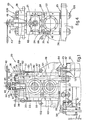
- Fig.I gives a front view of the section of a rolling stand. improved according to the invention;
- Fig.2 gives a side view of the rolling stand of Fig.I; .
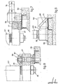
- Fig.3 shows a cutaway detail of the means which position the rolls axially;
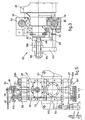
- Figs.4 & 5 show a front view of rolling stands employing differing types of means to regulate the distance between centres of the rolls;
- Figs.6, 7 & 8 show side views of some variants of the means. which anchor the rolling stand to the ground accord-. ing to the invention;
- Figs.9 & 10 give a side view of two variants of the equipment-carrying bar means.
- In the figures the same parts or parts having the same. functions bear the same reference numbers.
- In particular, the cartridge-
type rolling stand 20 shown in Figs.1 and 2 comprises two rolls 21-121 with horizontal axes, parallel to each other and equipped with frontal supporting .housings 22. - Moreover, said rolling
stand 20 consists of abase carrying structure 25 comprising lengthwise bars 26 and cross- .wise bars 27 which are rigidly and solidly fixed to each other. - Stay
rods 24 are installed through said crosswise bars. 27 and are clamped axially to saidbars 27; moreover, theheads 28 of the rollingstand 20 are installed above said .stay rods 24. - The assemblage thus formed is reciprocally fastened and serves to guide the
housings 22 which are installed so as to be able to slide on thestay rods 24 and between thebar 27 andhead 28. - The
stay rods 24 have their ends equipped with contrast and containingmeans 29 - In particular, the lower contrast and containment means I29 consist of an end which is solidly fixed to the stay rod. 24, whereas the upper containment means 229 consist of a
lock nut 30 which can be screwed onto the end of saidstay rod 24, and of aring nut 31 which can be screwed onto said lock nut. 30. - So as to clamp said
stay rod 24, thelock nut 30 is tightened until it is positioned against thehead 28. - Some fluid under pressure is then introduced into one . or more jacks 32 fitted into the
lock nut 30, so as to act on thepiston 33 located within said jacks 32. - Under the action of the fluid under pressure said pis-. .
ton 33 presses against thehead 28, and the latter in its turn .is held by anannular contrast surface 89. - In this way.a rigid supporting
structure 87 is formed which consists of theupright stay rods 24,upper head 28 and lower crosswisebar 27, all of which are fastened solidly to each other. - Thereafter the
ring nut 31 can be tightened up at leisu- .re until it presses against thehead 28, and after that the . .fluid under pressure in the jacks 32 can be withdrawn so that .the ring nut 3I itself now acts as the clamping element. - Adjustment of the distance between the axes (distance between centres) of the rolls 21-121 is obtained with suit- .able means 34 to adjust the distance between centres of the . rolls 21-121 and with
suitable means 35 to balance theupper roll 21. - In particular, said means 34 to adjust the distance between centres consist of spacer means or
distance pieces 36 and of adjustable screw pressing means 37 which are contained at least, partially within abox-wise cross piece 48. - Said spacer means 36 are located in the lower part of the rolling
stand 20 between thecrosswise bars 27 andlower housings 22 so as to position the lower roll I2I in relation to a pre-set rolling axis. - The adjustable screw means 37 cooperate with the
head 28, xhich comprises a throughfemale thread 38 machined cent- .rally and vertically through saidhead 28. - A
pressing bolt element 39 is screwed into thefemale thread 38 so as to press centrally against theupper housing 22. - Said pressure is balanced by a force of contrasting .vertical expansion exerted by the balancing means 35 located, .between the lower I22 and upper 22 housings near the
stay rods 24, as shown in Fig.4. - . Said balancing means 35 consist, in our example, of expansion springs 40 which are located in suitable chambers .4I machined in the upper part of the
housing 122 and which .act vertically against thepistons 88 solidly fixed to the .housings 22. - It is possible to envisage that the
upper roll 21 can .be balanced by employinghydraulic jacks 41. - . By regulating said screw means 37 it is possible to es- .tablish a given width or gap between the opposed surfaces of. the cylinders 21-121.
- Said regulation of said screw means 37 is obtained, in .particular, by acting on the suitably shaped upper part of .the
pressing bolt element 39 by means of a key of the torque- multiplier type, for instance. - A graduated
ring 44 is solidly connected, or can be so- .lidly connected, to thepressing bolt element 39 by key means .43 and cooperates axially with ashaft 45. - Said
shaft 45 is fitted on the outside of and coaxially with theelement 39 and bears circumferentially on its own outside atoothed crown 46 able to mesh with a transmission .chain 47. - In this way the rotation of the pressing bolt element . 39 is transmitted through the
ring 44,shaft 45,toothed crown 46 andtransmission chain 47 to a like system of crown 146, cylinder 145 andring 144, whereby said system cooperates with thepressing bolt element 139 opposite to said ele- .ment 39 in the same rolling stand 20 (Fig.2). - It is substantially possible to regulate both the screw means 37 of said rolling
stand 20 with onesingle key 42 sym- .metrically at the same time. - This enables the rolls 21-121 to be re-positioned quick- .ly and simply so as to bring the settings to the pre-establi- .shed sizes after each rolling phase.
- To be more exact, this operation is carried out by reducing the gap between the rolls 21-121 and reading (checking) .the size reached on the rotatable graduated
ring 44 and indi7 .cated by a stationary pointer (not shown here). - In particular, when the rolls are lying alongside each other, the stationary pointer indicates "nought" on the scale .of the graduated
ring 44. - Moreover, it is possible to act separately on each screw .means 37 by unfastening and raising the graduated
ring 44 so. that the latter does not cooperate with theshaft 45 and, .substantially, so that motion is not transmitted to thechain 47. - It should be noted that this particular system with a
transmission chain 47 enables the'employment of complicated and costly known transmission means to be avoided. - The rigidity of the rolling
stand 20 is maintained in .its upper part by thebox-wise cross piece 48, which connects the pair ofheads 28 and incorporates the adjustable screw pressing means 37 at least partially. - Fig.I shows some equipment-carrying bar means 49,which. are anchored to the
stand 20 and positioned vertically so as. to be able to cooperate with the rolling axis of said stand . 20. - It is envisaged that the position of alignment of said. means 49 with said axis can perhaps be regulated with screw . stays 50.
- Said screw stays 50 are solidly anchored (54) at one . end to said means 49 and cooperate at their other end, by means of their upper threaded end 5I, with through
holes 52 machined in the side of theheads 28 and with suitable traction and clamping means 53 which in this case consist of'a nut and lock nut. - Owing to the position they take up, said equipment- . carrying bar means 49 also act as lateral contrast and con- . tainment means for the housings 22-122.
- Fig.I also shows two different kinds of anchorage of the rolling
stand 20 to thefloor 55; one kind alone or both. kinds can be employed for the same rollingstand 20. - In particular, anchorage means 56 can be used which are shown on the right in Fig.I and comprise
bolts 57 for anchoring thestand 20 to thefloor 55. - The anchorage means 56 shown on the left in Fig.I con-, sist of a
guide 58 fixed to thefloor 55 with asupport 60 . and cooperating with agroove 59 having a spring in its lower part (61) within thestand 20 so as to enable the stand 20 tQ be positioned. - Figs.2 and 3 show axial positioning means 62 which serve to set the mutualaxial positions of the grooves (not shown) of the cylinders 21-121.
- Said positioning means 62 can cooperate at least with . one cylinder 21-121, the other cylinder 121-21 being possibly fixed.
- Said positioning means 62 consist of a fixed
support 63 connected to thehousings 22 and/or I22 and bearing axially . a threadedpin 65, which is welded or otherwise connected at. one of its lengthwise ends 64 to aflange 66. - Said
flange 66 cooperates with oneend 67 of the roll . 21 or 121, the other end of theroll - The axial clamping of said positioning means 62 is brought about by tightening axially, on the fixed
support 63, .two nuts 68-168 cooperating with the threaded part of thepin 65. - Said tightening can be performed with keys 69-169 of a known type, which are possibly equipped with a mechanism to invert the direction of actuation.
- Fig.3 also shows an element or pin 79 which can be screw- .ed and which can clamp the
stay rod 24 within thehole 23 by. means of acontrast notch 80. - Said clamping is necessary since said
stay rod 24 is in- .serted in such a way as to facilitate its entry within said . .hole 23. - Fig.4 shows an outer front view of the
stand 20 we have just described. - Said
stand 20 has a rolling axis which can possibly be .regulated during the course of successive rolling operations. carried out with the same pair of rolls 21-121. - Fig.5 shows a variant of the rolling stand wherein the rolling axis is fixed. Said fixed rolling axis is obtained in particular, by employing a pair of adjustable screw pressing means 37-137 for each pair of
housings 22 cooperating with the same end of the rolls 21-121. - Said adjustable screw pressing means 37-137 are located in the upper and lower parts of the
stand 20 so as to cooperate with theshoulders 28 and crosswisebars 27 to press at . the same time against the upper andlower housings 22 respectively. - It is possible to act with a key 42 on only one of the. adjustable screw pressing means 37, the motion being trans- . mitted to the opposed pressing means I37 by a transmission ,
system 70. - Said
transmission system 70 comprises chain means 71-171 able to cooperate with the respectivepressing means 37 and . to mesh with the gear wheels 73-173 at the ends of an upright shaft or pin 72 linking said chain means 71-171 - Figs.6-7-8 give a side view of some variants embodying. the
means 56 anchoring the rollingstand 20 to thefloor 55.. - In particular, Fig.6 shows means 56 for anchoring the . stand 20 centrally by insertion of suitably shaped protrusions 74, comprised on the
base structure 25 of thestand 20, withinbrackets 75 anchored to thefloor 55. - According to the lay-out of Fig.7, the ends 77 of the . crosswise bars 27 are clamped by a
contrast body 76 which is thrust against said ends 77 by ajack 78 solidly anchored to. thefloor 55. - The embodiment shown in the orthogonal projection of Fig.8 comprises hydraulic-bracket anchorage means 90 the working of which is the same as that described for the
means 29.. - Figs.9-IO show a side view of variants of the equipment-carrying
bar 49 and concern specifically some possible means. for positioning and clamping 8I said equipment-carrying bar . means 49. - In particular, Fig.9 shows rotatable means 8I consist-. ing of a pivoted (83-183)
jack 82 able to cause the rotation. of an articulated (85)structure 84 bearing the equipment-carrying bar means 49, from a position in contact with thestand 20 to a withdrawn position of said means 49 away from . saidstand 20 and viceversa. - In Fig.10 the
structure 84 bearing the equipment-carrying bar means 49 is solidly anchored to thefloor 55 so as to uphold means 49 of large sizes. - We have described here a preferential embodiment toge-. ther with variants of this invention, but further variants are possible for a person skilled in this field.
- Thus the shapes, sizes and proportions can be changed.. The
transmission system 70 can be disconnected so that the adjustable screw pressing means 37-137 of Fig.5 can be regulated separately. - It can be envisaged that the contrast and containment . means 29 consist of a simple nut. It is possible to visualise coupling means 86 located at the top of the
stand 20 to facilitate its removal (Fig.2). - All these and other variants are possible without departing thereby from the scope of the idea of the solution..
Claims (16)
- I. Improvements to cartridge-type rolling stands (20) equipped with two rolls (2I) lying side by side, and disposed with a horizontal or vertical axis, whereby said rolls (2I) . are of a replaceable type and are complete with housings (22), and whereby means (62) to position the rolls (2I) axially are comprised, said improvements being characterized by including one or more of the following: .- structure means (87) to support said housings (22), .- means to regulate the distance between centres (34) of said rolls (2I),- means to anchor (56) rolling stands (20) to the floor (55),- and means (81) to position and clamp equipment-carrying bar means (49), whereby means to balance the distance between centres (35) of said rolls (2I) are included.
- 2. Improvements to cartridge-type rolling stands (20)as in Claim I, characterized by the fact that the structure means (87) to support the housings (22) are constituted by cooper-.. ation between crosswise bars (27), stay rods (24) and the head (28), whereby said fixture bars (27) are connected together by lengthwise bars (26) and the two heads (28) are con-. nected by at least one cross piece (48)..
- 3. Improvements to cartridge-type rolling stands (20) . as in Claim I or 2, characterized by the fact that the stay . rods (24) are inserted into appropriate holes (I23) comprised in crosswise bars (27) and have at their lower end contrast . and containment means (129) cooperating with the lower part . of said crosswise bars (27), and whereby at least the upper . part of said stay rods (24) is conformed substantially with a contrast surface (89) cooperating with the head means (28), . and the upper part of said stay rods (24) is also inserted into said head means (28) and cooperates at its upper end with contrast and containment means (229).
- 4. Improvements to cartridge-type rolling stands (20) as in Claim I and in one or the other of the Claims thereafter, characterized by the fact,that the contrast and containment . means (29) cooperating with the upper part of the stay rods . (24) coming out of the head means (28) consist of lock nut means (30) and ring nut means (31), whereby said lock nut means (30) are equipped helpfully with jack means (32).
- 5. Improvements to cartridge-type rolling stands (20) . .as in Claim I and in one or another of the Claims thereafter, .characterized by the fact that the means (34) regulating the. .distance between centres of the rolls (21) comprise at least. .upper adjustable screw pressing means (37) which cooperate at .least partially with the heads (28) and upper housings (22),. whereby balancing means (35) are advantageously included and .are placed between and act by expansion between said upper . .and lower housings (22)..
- 6. Improvements to cartridge-type rolling stands (20) as in Claim I and in one or another of the Claims thereafter, characterized by the fact that the means (34) to regulate the distance between centres of the rolls (21) comprise, in coop- .eration with the adjustable screw pressing means (37), spacer .means (36) at least interposed between the crosswise bars (27) .and lower housings (22)..
- 7. Improvements to cartridge-type rolling stands (20) .as in Claim I and in one or another of the Claims thereafter. .up to Claim 5 inclusive, characterized by the fact that the . .means (34) to regulate the distance between centres comprise,. in cooperation with the upper adjustable screw pressing means (37), further lower adjustable screw pressing means (137) which cooperate at least partially with the crosswise bars (27) and lower housings (22), whereby said lower means (137) possibly cooperate mutually with said upper adjustable screw pressing. means (37) through transmission drive means (71-72).
- 8. Improvements to cartridge-type rolling stands (20) . as in Claim I and in one or another of the Claims thereafter, characterized by the fact that the adjustable screw means (37) consist of pressing bolt means (39) screwed through the heads (28) or crosswise bars (27) and cooperating with the housings (22), whereby said pressing bolt means (39) are connected coaxially by key means (43) to graduated ring means (44) cooperating axially with shaft means (45) which are mounted coaxially on said pressing bolt means (39) and which bear circumferentially on their outside a toothed crown (46) able to mesh with transmission means (47) so as to transmit motion between the upper adjustable screw means (37) of said rolling stand . (20).
- 9. Improvements to cartridge-type rolling stands (20) . as in Claim I and in one or another of the Claims thereafter, characterized by the fact that the means (56) anchoring the rolling stands (20) comprise bolt means (57) to anchor said . stands (20) to the floor (55).
- 10. Improvements to cartridge-type rolling stands (20) . as in Claim I and in one or another of the Claims thereafter. up to Claim 8 inclusive, characterized by the fact that the - means (56) anchoring the rolling stands (20) comprise a guide (58) secured to the floor (55) by a support (60) cooperating. with a groove (6I) having a spring in its lower part in said. rolling stand (20).
- II. Improvements to cartridge-type rolling stands (20) . as in Claim I and in one or another of the Claims thereafter. up to Claim 8 inclusive, characterized by the fact that the means (56) anchoring the rolling stand (20) are central and . .comprise shaped protrusions (74) on the base structure (25)of said stand (20), whereby said protrusions (74) can be inserted into brackets (75) anchored to the floor (55)..
- I2. Improvements to cartridge-type rolling stands (20) . as in Claim I and in one or another of the Claims thereafter. up to Claim 8 inclusive, characterized by the fact that the anchorage means (56) comprise a contrast body (76) clamping . the end (77) of the crosswise bars (27), said body (76) being thrust by jack means (78) screwed to the floor (55)..
- 13. Improvements to cartridge-type rolling stands (20) . as in Claim I and in one or another of the Claims thereafter. up to Claim 8 inclusive, characterized by the fact that the . anchorage means (56) comprise hydraulic bracket means (90) cooperating under pressure with the crosswise bars (27)..
- I4. Improvements to cartridge-type rolling stands (20) . as in Claim I and in one or another of the Claims thereafter, characterized by the fact that the means (81) positioning and clamping the equipment-carrying bar means (49) are secured to the floor (55)..
- I5. Improvements to'cartridge-type rolling stands (20) . as in Claim 1 and in one or another of the Claims thereafter .up to Claim 13 inclusive, characterized by the fact that the. means (81) positioning and clamping the equipment-carrying .bar means (49) comprise pivoted (83-183) jack means (82) able to cause the rotation of an articulated (85) structure (84) .bearing said equipment-carrying bar means (49) from a posit-, .ion in contact with the stand (20) to a withdrawn position of .said means (49) away from said stand (20) and viceversa.
- . I6. Cartridge-type rolling stands (20) having two side-by- .side rolls (21) and disposed with a horizontal or upright axis, .whereby said rolls (21) are of a replaceable type and are com- .plete with housings (22), and means (62) to position the rolls .(21) axially are comprised, said stands being characterized . by adopting one or more of the improvements of Claim I and .the Claims thereafter.
Applications Claiming Priority (2)
| Application Number | Priority Date | Filing Date | Title |
|---|---|---|---|
| IT8338981 | 1981-05-20 | ||
| IT83389/81A IT1146787B (en) | 1981-05-20 | 1981-05-20 | IMPROVEMENTS OF THE CARTRIDGE TYPE LIMITATION CAGES AND CARTRIDGE TYPE ROLLING CAGES SO PERFECTED |
Publications (2)
| Publication Number | Publication Date |
|---|---|
| EP0065935A2 true EP0065935A2 (en) | 1982-12-01 |
| EP0065935A3 EP0065935A3 (en) | 1983-06-01 |
Family
ID=11321152
Family Applications (1)
| Application Number | Title | Priority Date | Filing Date |
|---|---|---|---|
| EP82830107A Withdrawn EP0065935A3 (en) | 1981-05-20 | 1982-04-23 | Improvements to cartridge-type rolling stands and cartridge-type rolling stands thus improved |
Country Status (2)
| Country | Link |
|---|---|
| EP (1) | EP0065935A3 (en) |
| IT (1) | IT1146787B (en) |
Cited By (4)
| Publication number | Priority date | Publication date | Assignee | Title |
|---|---|---|---|---|
| US5113682A (en) * | 1989-04-28 | 1992-05-19 | Danieli & C. Officine Meccaniche S.P.A. | Cartridge rolling stand |
| US5400632A (en) * | 1990-12-12 | 1995-03-28 | S.I.M.A.C. S.P.A. | Demountable rolling stand |
| US5457979A (en) * | 1991-07-25 | 1995-10-17 | S.I.M.A.C. S.P.A. | Universal demountable rolling mill stand |
| EP0919298A2 (en) * | 1997-11-27 | 1999-06-02 | Sms Schloemann-Siemag Aktiengesellschaft | Housingless rolling stand |
Families Citing this family (1)
| Publication number | Priority date | Publication date | Assignee | Title |
|---|---|---|---|---|
| CN107321796B (en) * | 2017-08-11 | 2023-08-29 | 鑫鹏源智能装备集团有限公司 | Roller rack connecting device and method |
Citations (4)
| Publication number | Priority date | Publication date | Assignee | Title |
|---|---|---|---|---|
| DE1427851A1 (en) * | 1961-11-08 | 1971-07-29 | Davy & United Eng Co Ltd | Rolling mill |
| FR2152643A1 (en) * | 1971-09-06 | 1973-04-27 | Schloemann Ag | |
| DE2429375A1 (en) * | 1973-06-19 | 1975-01-09 | Nippon Kokan Kk | ROLLING MILL WITH PRE-TENSION |
| DE2506449A1 (en) * | 1974-02-18 | 1975-08-21 | Nippon Kokan Kk | PRE-TENSED UNIVERSAL ROLLING MILL |
-
1981
- 1981-05-20 IT IT83389/81A patent/IT1146787B/en active
-
1982
- 1982-04-23 EP EP82830107A patent/EP0065935A3/en not_active Withdrawn
Patent Citations (4)
| Publication number | Priority date | Publication date | Assignee | Title |
|---|---|---|---|---|
| DE1427851A1 (en) * | 1961-11-08 | 1971-07-29 | Davy & United Eng Co Ltd | Rolling mill |
| FR2152643A1 (en) * | 1971-09-06 | 1973-04-27 | Schloemann Ag | |
| DE2429375A1 (en) * | 1973-06-19 | 1975-01-09 | Nippon Kokan Kk | ROLLING MILL WITH PRE-TENSION |
| DE2506449A1 (en) * | 1974-02-18 | 1975-08-21 | Nippon Kokan Kk | PRE-TENSED UNIVERSAL ROLLING MILL |
Cited By (5)
| Publication number | Priority date | Publication date | Assignee | Title |
|---|---|---|---|---|
| US5113682A (en) * | 1989-04-28 | 1992-05-19 | Danieli & C. Officine Meccaniche S.P.A. | Cartridge rolling stand |
| US5400632A (en) * | 1990-12-12 | 1995-03-28 | S.I.M.A.C. S.P.A. | Demountable rolling stand |
| US5457979A (en) * | 1991-07-25 | 1995-10-17 | S.I.M.A.C. S.P.A. | Universal demountable rolling mill stand |
| EP0919298A2 (en) * | 1997-11-27 | 1999-06-02 | Sms Schloemann-Siemag Aktiengesellschaft | Housingless rolling stand |
| EP0919298A3 (en) * | 1997-11-27 | 2002-03-20 | SMS Demag AG | Housingless rolling stand |
Also Published As
| Publication number | Publication date |
|---|---|
| EP0065935A3 (en) | 1983-06-01 |
| IT8183389A0 (en) | 1981-05-20 |
| IT1146787B (en) | 1986-11-19 |
Similar Documents
| Publication | Publication Date | Title |
|---|---|---|
| EP0166478B1 (en) | Rolling stand of the type with tie-rods with oscillating supports with interchangeable intermediate holder bases | |
| US4557130A (en) | Housingless beam mill stand | |
| US5596899A (en) | Mill housings for cluster mills | |
| US4905493A (en) | Rolling stand which can be converted into a four-high stand or universal stand, and rolling line which employs such convertible stand | |
| EP0267420A3 (en) | Rolling stand with an axial shifting device for adjustable cylinders | |
| EP0065935A2 (en) | Improvements to cartridge-type rolling stands and cartridge-type rolling stands thus improved | |
| US5144828A (en) | Combined light-section mill and wire mill | |
| US6993951B1 (en) | Bending device for the working rolls of a hot-rolling frame | |
| US3572079A (en) | Rolling mills | |
| US3212314A (en) | Beam and plate rolling mill | |
| US5524469A (en) | Rolling mill stand | |
| US2525687A (en) | Separation device for rolling mills | |
| US3899910A (en) | Prestress type rolling mill | |
| EP0531676A1 (en) | Universal demountable rolling mill stand | |
| GB1178328A (en) | Improvements in Multi-Roll Stands. | |
| US5752404A (en) | Roll shifting system for rolling mills | |
| US3626739A (en) | Apparatus for roll counter-deflection in rolling stands | |
| US5787749A (en) | Rolling mill stand | |
| US3394575A (en) | Prestressed rolling mill | |
| US2835021A (en) | Roll stand lock | |
| US3516276A (en) | Rolling mills | |
| US5644939A (en) | Straightening machine for rolled beams | |
| US3861190A (en) | Rolling mills | |
| US4803862A (en) | Positioning of edge rolls | |
| US4162627A (en) | Rolling mill |
Legal Events
| Date | Code | Title | Description |
|---|---|---|---|
| PUAI | Public reference made under article 153(3) epc to a published international application that has entered the european phase |
Free format text: ORIGINAL CODE: 0009012 |
|
| AK | Designated contracting states |
Designated state(s): DE FR GB |
|
| PUAL | Search report despatched |
Free format text: ORIGINAL CODE: 0009013 |
|
| RHK1 | Main classification (correction) |
Ipc: B21B 31/04 |
|
| AK | Designated contracting states |
Designated state(s): DE FR GB |
|
| STAA | Information on the status of an ep patent application or granted ep patent |
Free format text: STATUS: THE APPLICATION HAS BEEN WITHDRAWN |
|
| 18W | Application withdrawn |
Withdrawal date: 19830718 |
|
| RIN1 | Information on inventor provided before grant (corrected) |
Inventor name: POLONI, ALFREDO |