EP0065759B2 - Method of manufacturing a row of continuous coupling elements for slide fasteners - Google Patents
Method of manufacturing a row of continuous coupling elements for slide fasteners Download PDFInfo
- Publication number
- EP0065759B2 EP0065759B2 EP82104409A EP82104409A EP0065759B2 EP 0065759 B2 EP0065759 B2 EP 0065759B2 EP 82104409 A EP82104409 A EP 82104409A EP 82104409 A EP82104409 A EP 82104409A EP 0065759 B2 EP0065759 B2 EP 0065759B2
- Authority
- EP
- European Patent Office
- Prior art keywords
- coupling elements
- filament
- row
- control unit
- continuous
- Prior art date
- Legal status (The legal status is an assumption and is not a legal conclusion. Google has not performed a legal analysis and makes no representation as to the accuracy of the status listed.)
- Expired
Links
Images

Classifications
-
- B—PERFORMING OPERATIONS; TRANSPORTING
- B29—WORKING OF PLASTICS; WORKING OF SUBSTANCES IN A PLASTIC STATE IN GENERAL
- B29D—PRODUCING PARTICULAR ARTICLES FROM PLASTICS OR FROM SUBSTANCES IN A PLASTIC STATE
- B29D5/00—Producing elements of slide fasteners; Combined making and attaching of elements of slide fasteners
- B29D5/06—Producing elements of slide fasteners; Combined making and attaching of elements of slide fasteners the interlocking members being formed by continuous helix
-
- A—HUMAN NECESSITIES
- A44—HABERDASHERY; JEWELLERY
- A44B—BUTTONS, PINS, BUCKLES, SLIDE FASTENERS, OR THE LIKE
- A44B19/00—Slide fasteners
- A44B19/42—Making by processes not fully provided for in one other class, e.g. B21D53/50, B21F45/18, B22D17/16, B29D5/00
-
- Y—GENERAL TAGGING OF NEW TECHNOLOGICAL DEVELOPMENTS; GENERAL TAGGING OF CROSS-SECTIONAL TECHNOLOGIES SPANNING OVER SEVERAL SECTIONS OF THE IPC; TECHNICAL SUBJECTS COVERED BY FORMER USPC CROSS-REFERENCE ART COLLECTIONS [XRACs] AND DIGESTS
- Y10—TECHNICAL SUBJECTS COVERED BY FORMER USPC
- Y10S—TECHNICAL SUBJECTS COVERED BY FORMER USPC CROSS-REFERENCE ART COLLECTIONS [XRACs] AND DIGESTS
- Y10S425/00—Plastic article or earthenware shaping or treating: apparatus
- Y10S425/814—Zipper
Definitions
- the present invention relates to a method of manufacturing a row of continuous coiled or zig- zag coupling elements of thermoplastic filamentary material, comprising the steps of: (a) forming the thermoplastic filamentary material into the row of continuous coiled or zig-zag coupling elements in an element forming unit, and (b) adjustably controlling the tensioning of the thermoplastic filamentary material prior to the latter's being formed on said element forming unit into the row of continuous coiled or zig-zag coupling elements by a tension control unit disposed upstream of said element-forming unit.
- thermoplastic filament is slackened before it continuously enters a coiling device, a weight is suspended from the slackened portion of the filament and the weight is adjusted to maintaining the filament under desired constant tensioning forces.
- the dimensions of the coupling elements that are manufactured are measured by the operator with a gage at suitable intervals of time, and the filament tension is varied by selectively adding or removing weights on the basis of the measurements.
- the gaging and weight adjusting processes have heretofore been tedious and time-consuming. It has also been unable to make coupling elements of uniform dimensions and shapes for the following reasons:
- the filament is made of synthetic resin such for example as nylon or polyester, and hence its properties such as elongation tend to change due to variations in environmental conditions such as temperature and humidity. Before being formed into continuous coupling elements, the filament is stored on a large-size bobbin.
- the filament properties are liable to vary at radially inward and outward positions or upper and lower positions on the filament wound around the bobbin, dependent on the amount of filament and the conditions under which the bobbin is mounted. Therefore, the filament as it is unwound from the bobbin is different in property from position to position on the filament.
- the filament is subject to continuous property variations while it is being continously applied to a coiling machine.
- the prior method has been unable to adjust the filament tension in a manner to cancel out such continuous property changes of the filament prior to the coiling thereof, with the result that the coupling elements as formed suffer from varying dimensions and shapes, which will prevent smooth intermeshing engagement of a pair of companion rows of coupling elements that are manufactured.
- a modified method of manufacturing also disclosed in US-A-3 987 533 differs from the method mentioned above in the last step by controlling the tension of the stringer tape forming member by a brake mechanism disposed upstream of the assembly station in response to the sensing to produce a continuus stringer having a substantially predetermined quantity of coupling elements per unit length of the tape.
- the number of fastening elements per unit length of the tape is greater than the predetermined number of friction force of the brake mechanism and thus the tension in the stringer tape forming member is reduced. Therefore this member is elongated less resulting in less fastening elements being secured in the assembly station per unit length on the tape.
- additional stretching occurs causing more fastening elements per unit length of the tape to be secured on the tape.
- the present invention seeks to provide a method of manufacturing a row of continuous coupling element, helically coiled or zigzag- shaped, which are of uniform dimension and shape, and of high precision and product quality.
- the invention further seeks to provide a method of manufacturing a row of continuous coupling elements of filamentary material while adjustably tensioning the latter to neutralize or cancel out changes in the properties thereof due to variations in ambient temperature, humidity and other environmental conditions.
- a method satisfying these requirements is characterized in that said tension control unit includes a roller around which the thermoplastic filamentary material is wound, and a brake coupled with a shaft of said roller, said brake being capable of producing a torque in proportion_ to a given control current voltage, and that the operation of said tension control unit is controlled by a control unit including a gage disposed downsteam of said element forming unit to measure a dimension of one of the continuous coupling elements as formed for generating an electric signal dependent on the measured dimension, a comparator for comparing the measured dimension with a reference value to produce an electric signal indicative of a dimensional error, if any, of the measured one of the continuous coupling elements, and an arithmetic control unit responsive to the dimensional error signal for supplying said tension control signal with a control current or voltage signal for controlling the torque of said brake to adjustably control the tensioning of the thermoplastic filamentary material.
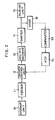
- in apparatus for continuous manufacturing a row of helically coiled coupling elements comprises in general a filament storage unit 10, a filament feeder 11, a tension control unit 12, a coiling machine 13, a coupling element shaper 14, a coupling element pairing unit 15, and a gage 16.
- the filament storage unit 10 includes a storage bobbin 18 on which thermoplastic filamentary material W is wound, a filament guide 19 disposed around the storage bobbin 18, and a rotor 20 coaxially rotatable around the storage bobbin 18.
- the rotor 20 is coupled to a drive shaft 22 rotatably journalled in a frame member 21 of a frame 31 mounted on a base 17.
- the rotor 20 is in the form of a cup in the illustrated embodiment, and has a horizontal shaft 23 extending coaxially with the drive shaft 22.
- the shaft 23 has a filament passage 24 extending coaxially and having one end opening behind the rotor 20.
- the rotor 20 has on its convex back a plurality of filament guide members 25.
- the filament guide 19 comprises a central sleeve 26 on which this storage bobbin 18 is mounted, and a guide arm 27 extending from the central sleeve 26 into underlying relation to the storage bobbin 18.
- the central sleeve 26 is rotatably mounted on the shaft 23 of the rotor 20.
- the guide arm 27 has a weight 28 which serves to keep the guide arm 27 positioned stationarily due to gravity.
- the storage bobbin 18, which is rotatable on the central sleeve 26, has a filament guide sleeve 29 having a guide hole (not shown) in its distal end portion which communicates with the filament passage 24 through the shaft 23.
- the filament W as it is unwound from the storage bobbin 18 passes through a guide hole 30 in the guide arm 27, goes to the distal end of the filament guide sleeve 29, passes through the guide hole in the filament guide sleeve 29 and the filament passage 24 in the shaft 23, emerges behind the rotor 20, and goes via the filament guide members 25 toward the filament feeder 11.
- the filament feeder 11 serves to withdraw the filament W positively from the filament storage unit 10 and to twist or rotate the filament W about its own axis.
- the filament feeder 11 comprises a fixed frame 45 dependent from an extension of the frame 31, and a rotatable frame 33 supported by a drive shaft 32 on the fixed frame 45, there being a pair of drive and pinch rollers 34, 35 rotatably mounted on the rotatable frame 33 and disposed closely in parallel relation to each other.
- the drive roller 34 has a shaft 36 rotatably journalled on the rotatable frame 33 and supporting thereon a pair of bevel gears 37, 38 that is held in mesh with a bevel gear 39 which is supported by a shaft 40 on the fixed frame 45.
- One of the pair of bevel gear (37, for example) is connected directly to the shaft 36 for driving the driver roller 34.
- the rotatable frame 33 is rotatable by a motor (not shown) through a belt 42 trained around a pulley 41 fixed to the drive shaft 32.
- the bevel gear 39 is also rotatable by the motor via a belt 44 trained around a pulley 43 fixed to the shaft 40.
- the drive roller 34 is thus rotatable by the bevel gear 39 through the bevel gear 37.
- the drive shaft 32 and the shaft 40 have coaxial holes (not shown) for passage therethrough the filament W as supplied from the filament storage unit 10.
- the filament W which is withdrawn from the filament storage unit 10 enters into the hole in the drive shaft 32, passes along one side of the pinch roller 35, is sandwiched between the drive and pinch rollers 34, 35, then makes a single convolution around the drive roller 34, and passes through the hole in the shaft 40 toward the tension control unit 12. Since the pulleys 41, 43 have different diameters, the rotatable frame 33 is rotatable with respect to the bevel gear 39, and hence the drive roller 34 is rotatable about its shaft 36 to positively feed the filament W wound therearound.
- the tension control unit 12 includes a frame 48 mounted on the extension of the frame 31 in overlying relation to the filament feeder 11.
- the tension control unit 12 includes a pair of front and rear rollers 46,47 rotatably mounted on the frame 48, the rear roller 47 having a shaft which is coupled to a brake 49.
- the brake 49 may preferably be a hysteresis brake for producing a torque in proportion to a given control current or voltage applied.
- the brake 49 may comprise an electromagnetic brake.
- the front roller 46 is idly rotatable on the frame 48.
- the filament W as supplied from the filament feeder 11 passes through a guide 50, is wound in two or three turns around the rear roller 47, then wound in two or three turns around the rear roller 47, then wound in one or two turns around the front roller 46, and goes out through a guide 51 toward the coiling machine 13.
- the coiling machine 13 is of a known construction including a frame 52 mounted on the frame 31 and supporting therein a bobbin 53 carrying thereon a core thread 54.
- a mandrel holder 55 is supported on the frame 52 and supports a coaxial mandrel 56.
- the mandrel holder 55 and the mandrel 56 have aligned holes for passage therethrough of the core thread 54.
- the coiling machine 13 also includes a coiling rotor 57 rotatably mounted on the frame 52 for coiling the filament W around the mandrel 56 into a row of successively formed helical coupling elements E.
- the helically coiled coupling elements E thus formed are then introduced into the element shaper 14.
- the element shaper 14 comprises a frame 58 mounted on the base 17, a die wheel 59 rotatably mounted on the frame 58 for shaping and setting the helically coiled coupling elements E thereon, a pair of pinch rollers 60, 61 rotatably supported on the frame 58 for pressing the coupling elements E against the die wheel 59, and a nozzle 62 mounted on the frame 58 for blowing cooling air against the coupling elements E as the latter leave the die wheel 59.
- the helically coiled coupling elements E which have been shaped and set by the element shaper 14 are then introduced into the element pairing unit 15.
- the element pairing unit 15 is shown in Figure 1 in its substantially half portion, and has a frame 64, a pair of guide rolls 65, 66 rotatably mounted on the frame 64, a tension roll 67 carried on the row of helically coiled coupling element E extending in suspended relation between the guide rolls 65, 66, a pair of upper and lower limit switches 68, 69 attached to the frame 64 for sensing upper and lower positions, respectively, of the tension roller 67 as it moves vertically, a pairing guide 72 mounted on the frame 64, and a pair of withdrawal rolls 73 rotatably mounted on the frame 64 downwardly of the pairing guide 72.
- the row of helically coiled coupling elements E and another row of helically coiled coupling elements E which have been formed by another apparatus identical to that which is shown in Figure 1, are mated together by the pairing guide 72 into a slide fastener chain F, which is discharged by the pair of withdrawal rolls 73.
- the gage 16 is fixedly mounted on the frame 64 of the element pairing unit 15.
- the gage 16 serves to measure a dimension of one of the coupling elements at a time which have been shaped and set by the element shaper 14 and to produce an electrical signal dependent on the measured dimension.
- the gage 16 comprises a guide member 71 having a channel (not shown) for guiding the row of helically coiled coupling elements E therein, and a dial gage 70 disposed in confronting relation to the guide member 71.
- a probe of the dial gage 70 is moved into contact with one of the coupling elements E to measure a dimension thereof for generating an electrical signal dependent thereon.
- the dial gage 70 may be replaced with a micrometer, a limit gage, a thickness gage, a photoelectric measurement means.
- thermoplastic filamentary material W is continuously supplied from the filament storage unit 10 into the coiling machine 13 while the filamentary material W is being coiled into a row of coupling elements E.
- the filamentary material W is fed by the filament feeder 11 as the rotatable frame 33 rotates in a direction to give the filament W a countertwist which will later be removed when the filament W is coiled around the mandrel 56 in the coiling machine 13.
- the drive roller 34 is caused to rotate about its shaft 36 to feed the filament W along toward the coiling machine 13 via the tension control unit 12.
- the row of helically coiled coupling elements E as they are formed by the coiling machine 13 is shaped and set by the element shaper 14, and then enters the element pairing unit 15.
- the row of coupling elements E is tensioned by the tension roll 67 between the guide rolls 65, 66.
- the rate of travel of the row of coupling elements E is adjustably controlled by vertical movement of the tension roll 67. More specifically, when the rate of travel of the row of coupling elements E is higher than that of the other row of coupling elements E while the withdrawal rolls 73 are at rest, the tension roll 67 moves downwardly until it first contacts the lower limit switch 69, whereupon the latter supplies an electric signal to actuate the withdrawal rolls 73.
- the probe of the dial gage 70 is brought into contact with one of the coupling elements E to measure a dimension thereof.
- the gage 16 is in the form of a photoelectric measurement device having no contacting part, the coupling elements E can be continuously measured for their dimensions while they are being longitudinally fed along.
- the dimension as measured by the gage 16 is converted into a corresponding electrical signal, which is then supplied to comparator 63 ( Figure 2) in which the electrical signal is compared with a reference value indicative of a desired coupling element dimension.
- the comparator 63 When the electrical signal and the reference value are not in agreement, the comparator 63 generates an electrical signal indicative of a dimensional error, which is supplied to an arithmetic control unit 74.
- the arithmetic control unit 74 is responsive to the supplied dimensional error signal for supplying the tension control unit 12 with a signal for controlling the brake 49 to adjustably control the tensioning of the filamentary material W.
- the tensioning forces can be varied by changing the braking forces imposed by the brake 49 on the filamentary material W in the tension control unit 12 in response to a control current or voltage supplied to the brake 49.
- a control current or voltage is produced by the arithmetic control unit 74 on the basis of a dimensional error determined by the comparator 63, as described above.
- the comparator 63 and the arithmetic control unit 74 may be in the form of a microcomputer which is programmed to effect the tension adjusting operation.
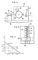
- FIGS 4 and 5 illustrate an apparatus for manufacturing a row of continuous zigzag coupling elements for slide fasteners.
- the apparatus includes a tension control unit 75 and an element forming unit 76, both mounted on a base 78.
- the tension control unit 75 comprises a frame 77 supported on the base 78, and a pair of guide rollers 79, 80 rotatably mounted on the frame 77, one of the guide rollers being adjustably braked.
- the element forming unit 76 comprises a frame 81 supported on the base 78, a die wheel 82 rotatably mounted on the frame 81 and having two rows of circumferentially staggered pins 83, 83 disposed one on each side of a central groove 84 in the die wheel 82, and a bending roller 85 rotatably supported on the frame 81 and having a peripheral edge fitted in the central groove 84.
- a guide member 88 is movable back and forth in the axial direction of the die wheel 82 across the central groove 84 and has a guide hole 87 for passage therethrough of a filament W of thermoplastic material.
- the filament W is supplied via the tension control unit 75 into the element forming unit 76, in which the filament W passes through the guide hole 87.
- the filament W is caused to extend alternately around the pins 83 across the central groove 84 as shown in Figure 5.
- the filament W as thus bent into a zigzag form is pushed by the bending roller 85 into the central groove 84 to form a row of zigzag coupling elements E' having parallel legs.
- the zigzag coupling elements E' which have left the die wheel 82 are measured for dimensions thereof by a gage 89 mounted on the frame 81 for controlling the tension control unit 75 to adjustably control the tension to which the filament W is subjected prior to introduction into the element forming unit 76.
- helically coiled or zigzag coupling elements can be dimensioned as desired even when filamentary material from which the coupling elements are formed is varied in properties due to temperature, humidity, storage conditions, and other factors.
- slide fastener coupling elements of uniform dimension, better accuracy, and stable quality can be manufactured.
- the rate of production of coupling elements is increased since there are no manual measurement and weight replacement needed.
Landscapes
- Engineering & Computer Science (AREA)
- Mechanical Engineering (AREA)
- Moulding By Coating Moulds (AREA)
- Slide Fasteners (AREA)
- Portable Nailing Machines And Staplers (AREA)
Applications Claiming Priority (2)
| Application Number | Priority Date | Filing Date | Title |
|---|---|---|---|
| JP77560/81 | 1981-05-22 | ||
| JP56077560A JPS57192507A (en) | 1981-05-22 | 1981-05-22 | Production of coil like or zigzag like fastener element |
Publications (4)
| Publication Number | Publication Date |
|---|---|
| EP0065759A2 EP0065759A2 (en) | 1982-12-01 |
| EP0065759A3 EP0065759A3 (en) | 1984-09-19 |
| EP0065759B1 EP0065759B1 (en) | 1986-09-24 |
| EP0065759B2 true EP0065759B2 (en) | 1990-10-10 |
Family
ID=13637394
Family Applications (1)
| Application Number | Title | Priority Date | Filing Date |
|---|---|---|---|
| EP82104409A Expired EP0065759B2 (en) | 1981-05-22 | 1982-05-19 | Method of manufacturing a row of continuous coupling elements for slide fasteners |
Country Status (12)
| Country | Link |
|---|---|
| US (1) | US4433537A (cg-RX-API-DMAC7.html) |
| EP (1) | EP0065759B2 (cg-RX-API-DMAC7.html) |
| JP (1) | JPS57192507A (cg-RX-API-DMAC7.html) |
| KR (1) | KR840001526B1 (cg-RX-API-DMAC7.html) |
| AU (1) | AU534161B2 (cg-RX-API-DMAC7.html) |
| BR (1) | BR8202986A (cg-RX-API-DMAC7.html) |
| CA (1) | CA1188495A (cg-RX-API-DMAC7.html) |
| DE (1) | DE3273416D1 (cg-RX-API-DMAC7.html) |
| ES (1) | ES8304844A1 (cg-RX-API-DMAC7.html) |
| GB (1) | GB2099071B (cg-RX-API-DMAC7.html) |
| HK (1) | HK62388A (cg-RX-API-DMAC7.html) |
| MY (1) | MY8700420A (cg-RX-API-DMAC7.html) |
Families Citing this family (4)
| Publication number | Priority date | Publication date | Assignee | Title |
|---|---|---|---|---|
| JP3275932B2 (ja) * | 1994-08-02 | 2002-04-22 | ワイケイケイ株式会社 | スライドファスナー用連続エレメント列の成形方法及び装置 |
| US6884869B2 (en) | 2001-04-30 | 2005-04-26 | Seattle Genetics, Inc. | Pentapeptide compounds and uses related thereto |
| JP4602120B2 (ja) * | 2005-03-02 | 2010-12-22 | Ykk株式会社 | ファスナーストリンガ連続製造機のファスナーテープ供給装置 |
| WO2015092852A1 (ja) * | 2013-12-16 | 2015-06-25 | Ykk株式会社 | 連続ファスナーエレメント製造機の芯紐供給装置 |
Family Cites Families (13)
| Publication number | Priority date | Publication date | Assignee | Title |
|---|---|---|---|---|
| US2541728A (en) | 1946-06-29 | 1951-02-13 | Wahl Brothers | Apparatus and method for making separable fasteners |
| US2817206A (en) | 1953-11-10 | 1957-12-24 | Cue Fastner Inc | Apparatus for making coils and other twisted and mated elements |
| US2907066A (en) | 1954-03-25 | 1959-10-06 | Wahl Brothers | Method and apparatus for making separable fasteners |
| GB1133846A (en) | 1965-04-28 | 1968-11-20 | Opti Holding Ag | Improvements in or relating to the production of sliding clasp fastener interlocking elements from thermoplastic filaments |
| US3572023A (en) | 1969-01-23 | 1971-03-23 | Henry Rogers | Coiling apparatus |
| RO85146B (ro) | 1969-09-16 | 1984-11-30 | Opti-Holding Ag | DISPOZITIV PENTRU îNFASURAREA îN MOD CONTINUU A UNUI ELEMENT ELICOIDAL DE FERMOAR |
| US3613347A (en) | 1970-05-08 | 1971-10-19 | Turbo Machine Co | Yarn twist measuring instrument |
| FI56785C (fi) | 1972-11-16 | 1980-04-10 | Opti Patent Forschung Fab | Foerfarande och anordning foer framstaellning av kontinuerliga foerslutningsrader foer dragked ur termoplastiskt konstaemne |
| US3945181A (en) | 1973-08-11 | 1976-03-23 | Toray Industries, Inc. | Process and apparatus for measuring uniformity of physical properties of yarn |
| PH12625A (en) | 1974-09-05 | 1979-07-05 | Yoshida Kogyo Kk | Method and apparatus for manufacturing helically coiled coupling elements |
| JPS5130039A (ja) * | 1974-09-05 | 1976-03-13 | Yoshida Kogyo Kk | Suraidofuasunaanokoirujoerementonoseizohoho oyobi sonosochi |
| US4090832A (en) | 1975-07-16 | 1978-05-23 | Textron Inc. | Apparatus for making slide fastener |
| US3987533A (en) * | 1975-10-20 | 1976-10-26 | Textron, Inc. | Method and apparatus for manufacturing slide fastener stringer with improved fastening element count |
-
1981
- 1981-05-22 JP JP56077560A patent/JPS57192507A/ja active Granted
-
1982
- 1982-05-06 AU AU83473/82A patent/AU534161B2/en not_active Ceased
- 1982-05-12 GB GB8213718A patent/GB2099071B/en not_active Expired
- 1982-05-18 US US06/379,290 patent/US4433537A/en not_active Expired - Fee Related
- 1982-05-19 EP EP82104409A patent/EP0065759B2/en not_active Expired
- 1982-05-19 DE DE8282104409T patent/DE3273416D1/de not_active Expired
- 1982-05-20 BR BR8202986A patent/BR8202986A/pt unknown
- 1982-05-21 CA CA000403492A patent/CA1188495A/en not_active Expired
- 1982-05-21 KR KR8202233A patent/KR840001526B1/ko not_active Expired
- 1982-05-22 ES ES512477A patent/ES8304844A1/es not_active Expired
-
1987
- 1987-12-30 MY MY420/87A patent/MY8700420A/xx unknown
-
1988
- 1988-08-18 HK HK623/88A patent/HK62388A/xx unknown
Also Published As
| Publication number | Publication date |
|---|---|
| EP0065759A2 (en) | 1982-12-01 |
| GB2099071A (en) | 1982-12-01 |
| MY8700420A (en) | 1987-12-31 |
| JPS57192507A (en) | 1982-11-26 |
| HK62388A (en) | 1988-08-26 |
| KR840001526B1 (ko) | 1984-10-04 |
| AU534161B2 (en) | 1984-01-05 |
| EP0065759A3 (en) | 1984-09-19 |
| JPS638903B2 (cg-RX-API-DMAC7.html) | 1988-02-25 |
| BR8202986A (pt) | 1983-05-03 |
| ES512477A0 (es) | 1983-04-16 |
| ES8304844A1 (es) | 1983-04-16 |
| EP0065759B1 (en) | 1986-09-24 |
| AU8347382A (en) | 1982-11-25 |
| CA1188495A (en) | 1985-06-11 |
| US4433537A (en) | 1984-02-28 |
| DE3273416D1 (en) | 1986-10-30 |
| KR830009749A (ko) | 1983-12-23 |
| GB2099071B (en) | 1985-03-13 |
Similar Documents
| Publication | Publication Date | Title |
|---|---|---|
| KR930010369B1 (ko) | 반죽의 스트레칭 방법 및 장치 | |
| KR940005835A (ko) | 품질신호의 출력으로 열가소성 플라스틱 엔드리스물질을 제조 및/또는 처리하고 권하는 방법 및 권취기 | |
| KR101346007B1 (ko) | 통형 연사 제조 장치 | |
| EP0065759B2 (en) | Method of manufacturing a row of continuous coupling elements for slide fasteners | |
| US4192061A (en) | Process and apparatus for manufacture of parallel lead electronic components | |
| US4040240A (en) | Method and apparatus for doubling and twisting a yarn by a two-step changeover system | |
| US5293906A (en) | Circular loom for and method of weaving ribbon-shaped weft | |
| US4479835A (en) | Apparatus and method for forming wire reinforced helically fabricated tubing | |
| US20060196608A1 (en) | Fastener tape supply unit of fastener stringer continuous manufacturing apparatus | |
| US4491003A (en) | Fabrication of helically-wound spirals for metal wire belts | |
| CN111069481B (zh) | 一种汽车用搭铁编织线整形计长收线装置 | |
| RU2126732C1 (ru) | Устройства для центровки (варианты), разгибания и уплощения трубы | |
| JP4583585B2 (ja) | 長尺無端歯付ベルトの製造装置及び歯数計数方法 | |
| CN216941799U (zh) | 复合材料缠绕收紧装置 | |
| US5164205A (en) | Apparatus for stamping monofilament for slider fastener coupling elements | |
| US5115659A (en) | Process for producing component for tire and apparatus therefor | |
| US3445560A (en) | Method for making spiral-shaped continuous rows of slide fastener elements | |
| DE4224454C2 (de) | Verfahren zur Regelung der Temperatur eines Heizmediums zur Erhitzung eines synthetischen Fadens und Texturiereinrichtung für einen synthetischen Faden | |
| DE69406456T2 (de) | Verfahren und maschine zur herstellung von elastische bändern und also erhaltene bänder | |
| CN118254325B (zh) | 一种膜片挤压成型设备及其工艺 | |
| RU2245208C1 (ru) | Способ изготовления из проволоки волнообразной ленты и автомат для изготовления из проволоки волнообразной ленты | |
| JPH04320832A (ja) | 自動車タイヤのベルト補強コード巻付け装置 | |
| US3112604A (en) | Twisted plastic sticks | |
| CN217922500U (zh) | 织带装置 | |
| JPH0274206A (ja) | 長い連続スライドファスナ帯片にギャップを形成するタイミング制御ギャップ機 |
Legal Events
| Date | Code | Title | Description |
|---|---|---|---|
| PUAI | Public reference made under article 153(3) epc to a published international application that has entered the european phase |
Free format text: ORIGINAL CODE: 0009012 |
|
| AK | Designated contracting states |
Designated state(s): BE DE FR IT NL |
|
| PUAL | Search report despatched |
Free format text: ORIGINAL CODE: 0009013 |
|
| AK | Designated contracting states |
Designated state(s): BE DE FR IT NL |
|
| 17P | Request for examination filed |
Effective date: 19841220 |
|
| GRAA | (expected) grant |
Free format text: ORIGINAL CODE: 0009210 |
|
| AK | Designated contracting states |
Kind code of ref document: B1 Designated state(s): BE DE FR IT NL |
|
| ITF | It: translation for a ep patent filed | ||
| REF | Corresponds to: |
Ref document number: 3273416 Country of ref document: DE Date of ref document: 19861030 |
|
| ET | Fr: translation filed | ||
| PLBI | Opposition filed |
Free format text: ORIGINAL CODE: 0009260 |
|
| 26 | Opposition filed |
Opponent name: OPTI PATENT,- FORSCHUNGS- UND FABRIKATIONS- AG Effective date: 19870617 |
|
| NLR1 | Nl: opposition has been filed with the epo |
Opponent name: OPTI PATENT,-FORSCHUNGS-UND FABRIKATIONS-AG |
|
| PUAH | Patent maintained in amended form |
Free format text: ORIGINAL CODE: 0009272 |
|
| STAA | Information on the status of an ep patent application or granted ep patent |
Free format text: STATUS: PATENT MAINTAINED AS AMENDED |
|
| 27A | Patent maintained in amended form |
Effective date: 19901010 |
|
| AK | Designated contracting states |
Kind code of ref document: B2 Designated state(s): BE DE FR IT NL |
|
| ET3 | Fr: translation filed ** decision concerning opposition | ||
| ITF | It: translation for a ep patent filed | ||
| NLR2 | Nl: decision of opposition | ||
| NLR3 | Nl: receipt of modified translations in the netherlands language after an opposition procedure | ||
| ITTA | It: last paid annual fee | ||
| PGFP | Annual fee paid to national office [announced via postgrant information from national office to epo] |
Ref country code: BE Payment date: 19940222 Year of fee payment: 13 |
|
| PGFP | Annual fee paid to national office [announced via postgrant information from national office to epo] |
Ref country code: FR Payment date: 19940420 Year of fee payment: 13 |
|
| PGFP | Annual fee paid to national office [announced via postgrant information from national office to epo] |
Ref country code: NL Payment date: 19940531 Year of fee payment: 13 Ref country code: DE Payment date: 19940531 Year of fee payment: 13 |
|
| PG25 | Lapsed in a contracting state [announced via postgrant information from national office to epo] |
Ref country code: BE Effective date: 19950531 |
|
| BERE | Be: lapsed |
Owner name: YOSHIDA KOGYO K.K. Effective date: 19950531 |
|
| PG25 | Lapsed in a contracting state [announced via postgrant information from national office to epo] |
Ref country code: NL Effective date: 19951201 |
|
| NLV4 | Nl: lapsed or anulled due to non-payment of the annual fee |
Effective date: 19951201 |
|
| PG25 | Lapsed in a contracting state [announced via postgrant information from national office to epo] |
Ref country code: DE Effective date: 19960201 |
|
| PG25 | Lapsed in a contracting state [announced via postgrant information from national office to epo] |
Ref country code: FR Effective date: 19960229 |
|
| REG | Reference to a national code |
Ref country code: FR Ref legal event code: ST |
|
| REG | Reference to a national code |
Ref country code: FR Ref legal event code: ST |