EP0065306A2 - Sheet feeding device for a copying machine - Google Patents
Sheet feeding device for a copying machine Download PDFInfo
- Publication number
- EP0065306A2 EP0065306A2 EP82104313A EP82104313A EP0065306A2 EP 0065306 A2 EP0065306 A2 EP 0065306A2 EP 82104313 A EP82104313 A EP 82104313A EP 82104313 A EP82104313 A EP 82104313A EP 0065306 A2 EP0065306 A2 EP 0065306A2
- Authority
- EP
- European Patent Office
- Prior art keywords
- copy sheet
- feed roller
- pair
- copy
- stack
- Prior art date
- Legal status (The legal status is an assumption and is not a legal conclusion. Google has not performed a legal analysis and makes no representation as to the accuracy of the status listed.)
- Granted
Links
Images

Classifications
-
- G—PHYSICS
- G03—PHOTOGRAPHY; CINEMATOGRAPHY; ANALOGOUS TECHNIQUES USING WAVES OTHER THAN OPTICAL WAVES; ELECTROGRAPHY; HOLOGRAPHY
- G03G—ELECTROGRAPHY; ELECTROPHOTOGRAPHY; MAGNETOGRAPHY
- G03G15/00—Apparatus for electrographic processes using a charge pattern
- G03G15/65—Apparatus which relate to the handling of copy material
- G03G15/6502—Supplying of sheet copy material; Cassettes therefor
-
- B—PERFORMING OPERATIONS; TRANSPORTING
- B65—CONVEYING; PACKING; STORING; HANDLING THIN OR FILAMENTARY MATERIAL
- B65H—HANDLING THIN OR FILAMENTARY MATERIAL, e.g. SHEETS, WEBS, CABLES
- B65H3/00—Separating articles from piles
- B65H3/02—Separating articles from piles using friction forces between articles and separator
- B65H3/06—Rollers or like rotary separators
- B65H3/0669—Driving devices therefor
Definitions
- the invention relates to a paper feed device of a copying machine, which has a rotatably driven photo drum, with a copy sheet magazine receiving a copy sheet stack, with a pair of feed rollers arranged at a distance from the discharge opening thereof, which, in adaptation to the copying cycle, is controlled to feed a copy sheet fed from the copy sheet magazine to the photo drum intermittently is drivable, and with a arranged above the copy sheet magazine, under pressure with the top copy sheet of the copy sheet stack for advancing this copy sheet with its leading edge in the roller gap of the (still stationary) feed roller pair interacting feed roller, which intermittently and by means of a rotating control disc drive device is drivable in time before the pair of feed rollers.
- This known paper feed device is structurally very complex and, moreover, difficult to set, since a very precise adjustment of cam disks and levers is required for exact copy sheet guidance.
- the components used for the control are very susceptible to wear due to their structural design, so that maintenance-free operation of the paper feed device is generally not to be expected even over longer service lives.
- Another disadvantage of the known paper feed device is that the switching on of the feed roller pair must be carried out separately not only in coordination with the rotation of the photo drum, but also in coordination with the driving of the feed roller by means of additional switching elements. Seen overall, a large number of precision parts are required for the known paper feed device, as a result of which the entire construction of the paper feed device is not only very complex to manufacture, but also in maintenance.
- the object of the invention is to improve a paper feed device of the type mentioned at the outset in such a way that a long service life and a control system which is less susceptible to faults are created, which nevertheless enable high control accuracy with a simple and robust construction.
- the complicated and very difficult to adjust lever arrangements used in the known paper feed device are thus eliminated.
- the invention makes it possible to control the movement cycle of the feed roller and the pair of feed rollers by means of a single control disk which rotates once for each paper feed cycle in chronological coordination with the rotation of the photo drum.
- the drive times of these two conveying devices can be determined in a simple manner by the respective location of the dental arch segments on the control disk and the length of the dental arch segments.
- the dental arch segments and the associated drive pinions must be arranged such that each dental arch segment engages with only one of the drive pinions and passes the other drive pinion without engagement. This can be achieved, for example, by different pitch circle diameters of the dental arch segment and the formation of one dental arch segment as an internally toothed segment and the other as an externally toothed segment. Depending on the direction of rotation of the control disk and the selection of that roller of the feed roller pair that has the drive pinion, the one gear segment then interacts with the drive pinion assigned to it via a reversing wheel.
- both internal or external teeth Dental arch segments and correspondingly axially offset the drive pinion.
- one dental arch segment can be formed on the circumference of the control disk and the other dental arch segment protrude from an end face of the control disk.
- both dental arch segments are arranged offset to the same axis side of the control disk so that they both protrude axially therefrom, a circumferential groove for the contact-free passage of the control disk on the drive pinion interacting with the other dental arch segment being formed between the further projecting dental arch segment and the control disk .
- the copy sheet magazine can be articulated at its end facing away from the feed roller and can be held by the pressure of a spring which is supported on the frame of the copying machine in such a way that the uppermost copy sheet always rests on the feed roller with a certain pressure regardless of the height of the copy sheet stack. It is also possible to use a fixed copy sheet magazine which has a movable base plate which is pressed upwards in a resilient manner. However, the copy sheet magazine is preferably supported so as to be freely pivotable about an axis running parallel to the axis of the feed roller and arranged between the latter and the center of gravity of the copy sheet magazine for pressing the copy sheet stack under the feed roller. Alternatively or additionally, it is also possible to arrange a weight at the end of the pivotally supported copy sheet magazine facing away from the feed roller, by means of which the contact of the top sheet of the stack in each case with the feed roller is ensured.
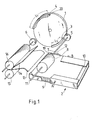
- FIG. 1 shows a control disk 1 which is driven via a shaft, not shown, of a copying machine for one revolution per copying operation.
- the arc length 1 3 of the dental arch segment 3 is smaller than the arc length l4 of the dental arch segment 4.
- the dental arch segments 3, 4 are axially offset from one another, the dental arch segment 3 the end of the control disc 1 is axially closer than the dental arch segment 4.
- the part of the dental arch segment 4 facing the control disc 1 is provided with a circumferential groove 20, the width and depth of which is dimensioned such that the drive pinion 5 during the rotation of the control disc 1 makes this part of the dental arch segment non-contact can happen.
- the feed roller 8 can - as shown in FIG. 1 - be designed as a conveyor roller or in the form of several individual rollers arranged parallel to each other.
- the copy sheet magazine 2 is designed in the form of a box open at the top, which is provided with so-called separators 11 and 12 at its end facing the feed roller 8.
- the separators 11 and 12 are arranged such that they cover the upwardly open opening of the box in the area of the front corners by triangular plates 19.
- the plates 19 cause the uppermost copy sheet to bulge during operation of the feed roller 8, thereby ensuring the separation of the top copy sheet from the copy sheet underneath.
- the copy sheet magazine 2 is pivotally mounted on the longitudinal side of the box, from which projecting axis parts A and B, which are supported with their free end in the housing of the copying machine.
- the axis parts A, B are arranged parallel to the axis of the feed roller 8 between the latter and the center of gravity of the copy sheet magazine 2. This ensures that the copy sheet magazine is swiveled clockwise without additional device under the force of gravity, as a result of which the top copy sheet is pressed against the feed roller 8 from below, regardless of the height of the copy sheet stack.
- an additional counterweight 10 can be provided on the end of the copy sheet magazine 2 facing away from the feed roller 9 in order to ensure a sufficiently strong pressure between the top copy sheet and the feed roller 8 even when the copy sheet magazine 2 is almost empty.
- two steering plates 13, 14 are arranged such that their ends facing a pair of feed rollers 15, 16 form a discharge slot.
- the end of the lower steering plate 13 pointing towards the feed roller 8 is bent in the clockwise direction, so that even an incorrectly running copy sheet is caught with its leading edge and directed in the direction of the pair of feed rollers 15, 16.
- control disk 1 When the copying process begins, the control disk 1 is rotated counterclockwise in the direction of the arrow by a drive device (not shown in detail here). Due to the engagement of the drive pinion 5 with the dental arch segment 3, the feed roller 8 is rotated clockwise via the drive shaft 7. As a result, the uppermost copy sheet of the copy sheet stack 9 is withdrawn from the copy sheet stack 9 and the leading edge of the copy sheet reaches the guide delimited by the two steering plates 13 and 14 and runs through the output slot in the roller gap delimited by the as yet non-driven feed roller pair 15, 16 on the feed rollers 15, 16.
- the copy sheet is puffed up in the guide delimited by the steering plates 13 and 14, as a result of which the copy sheet is aligned with the feed rollers 15, 16 and is provided at the correct position for synchronous operation with the photo drum.
- the copy sheet remains in this position until the drive pinion 6 engages with the dental arch segment 4. If this happens, the copy sheet engaging with its leading edge in the nip is conveyed away by the pair of feed rollers 15, 16.
- the length 1 3 of the toothing of the curved tooth segment 3 is dimensioned such that, taking into account the transmission ratio between the dental arch segment 3 and drive pinion 5 or feed roller 8, the top copy sheet with its leading edge reaches the roller gap delimited by the pair of feed rollers 15, 16 and also the above-mentioned supply loop of the copy sheet is formed in the guide formed by the steering plates 13, 14.
- the length 1 4 of the dental arch segment 4 is dimensioned taking into account the individual gear ratios of the dental arch segment 4, drive pinion 6 and feed roller pair 15, 16 such that the copying sheet lying with its leading edge against the nip is conveyed to its full length.
- Known sensors are provided on the bottom of the copy sheet magazine 2 which, when the copy sheet magazine is empty, ensure that the drive of the control disk 1 is switched off by means of corresponding switching devices.
Landscapes
- Physics & Mathematics (AREA)
- General Physics & Mathematics (AREA)
- Engineering & Computer Science (AREA)
- Mechanical Engineering (AREA)
- Sheets, Magazines, And Separation Thereof (AREA)
Abstract
Description
Die Erfindung betrifft eine Papierzuführeinrichtung einer Kopiermaschine, die eine drehbar angetriebene Fototrommel aufweist, mit einem einen Kopierblattstapel aufnehmenden Kopierblattmagazin, einem im Abstand von dessen Ausgabemündung angeordneten Zuführrollenpaar, welches in Anpassung an den Kopierzyklus gesteuert zum Zuführen eines aus dem Kopierblattmagazin vorgeschobenen Kopierblattes zu der Fototrommel intermittierend antreibbar ist, und mit einer über dem Kopierblattmagazin angeordneten, unter Druck mit dem jeweils obersten Kopierblatt des Kopierblattstapels zum Vorschieben dieses Kopierblattes mit dessen vorlaufenden Kante in den Rollenspalt des (noch stillstehenden) Zuführrollenpaares zusammenwirkenden Vorschubrolle, die mittels einer eine umlaufende Steuerscheibe aufweisenden Antriebseinrichtung intermittierend und zeitlich vor dem Zuführrollenpaar antreibbar ist.The invention relates to a paper feed device of a copying machine, which has a rotatably driven photo drum, with a copy sheet magazine receiving a copy sheet stack, with a pair of feed rollers arranged at a distance from the discharge opening thereof, which, in adaptation to the copying cycle, is controlled to feed a copy sheet fed from the copy sheet magazine to the photo drum intermittently is drivable, and with a arranged above the copy sheet magazine, under pressure with the top copy sheet of the copy sheet stack for advancing this copy sheet with its leading edge in the roller gap of the (still stationary) feed roller pair interacting feed roller, which intermittently and by means of a rotating control disc drive device is drivable in time before the pair of feed rollers.
Damit eine qualitativ hochwertige Übertragung des auf der Fototrommel haftenden Tonerbildes auf das Kopierblatt gewährleistet ist, ist eine zeitlich exakte Steuerung der Papierzuführeinrichtung für den jeweiligen Kopierzyklus eine unabdingbare Forderung. Dies gilt insbesondere für schnellarbeitende Kopiermaschinen.In order to ensure a high-quality transfer of the toner image adhering to the photo drum onto the copy sheet, an exact time control of the paper feed device for the respective copying cycle is an essential requirement. This applies in particular to high-speed copying machines.
Bei einer bekannten Papierzuführeinrichtung der eingangs erwähnten Bauart (DE-PS 25 06 534) sind auf der Achse der Fototrommel zwei Kurvenscheiben angeordnet, die jeweils mit einem Hebel in Eingriff stehen. Dabei wird durch den einen Hebel für jeden Papierschubvorgang das Auf- und Absenken der Vorschubrolle, und durch den anderen Hebel mittels einer Zahnstange der Antrieb derselben gesteuert. Diese Steuerung hat jedoch keinen Einfluß auf den Antrieb des Zuführrollenpaares, der durch einen gesonderten Zahnriemen und eine Magnetkupplung erfolgt.In a known paper feeder of the beginning mentioned type (DE-PS 25 06 534) two cams are arranged on the axis of the photo drum, each of which is in engagement with a lever. The up and down of the feed roller is controlled by the one lever for each paper feed process, and the drive thereof is controlled by the other lever by means of a rack. However, this control has no influence on the drive of the pair of feed rollers, which is carried out by a separate toothed belt and a magnetic coupling.
Diese bekannte Papierzuführeinrichtung ist konstruktiv sehr aufwendig und darüber hinaus schwierig einzustellen, da für eine exakte Kopierblattführung eine sehr genaue Abstimmung von Kurvenscheiben und Hebel erforderlich ist. Darüberhinaus sind bei der bekannten Papierzuführeinrichtung die relevanten für die Steuerung verwendeten Bauteile aufgrund ihrer konstruktiven Auslegung sehr verschleißanfällig, so daß ein wartungsfreier Betrieb der Papierzuführeinrichtung auch über größere Standzeiten hin in der Regel nicht zu erwarten ist. Ein weiterer Nachteil der bekannten Papierzuführeinrichtung besteht darin, daß das Einschalten des Zuführrollenpaares nicht nur in Abstimmung auf die Drehung der Fototrommel, sondern auch in Abstimmung auf das Antreiben der Vorschubrolle mittels zusätzlicher Schaltorgane gesondert durchgeführt werden muß. Insgesamt gesehen sind für die bekannte Papierzuführeinrichtung eine große Anzahl von Präzisionsteilen erforderlich, durch die die gesamte Konstruktion der Papierzuführeinrichtung nicht nur sehr aufwendig in der Herstellung, sondern auch in der Wartung ist.This known paper feed device is structurally very complex and, moreover, difficult to set, since a very precise adjustment of cam disks and levers is required for exact copy sheet guidance. In addition, in the known paper feed device, the components used for the control are very susceptible to wear due to their structural design, so that maintenance-free operation of the paper feed device is generally not to be expected even over longer service lives. Another disadvantage of the known paper feed device is that the switching on of the feed roller pair must be carried out separately not only in coordination with the rotation of the photo drum, but also in coordination with the driving of the feed roller by means of additional switching elements. Seen overall, a large number of precision parts are required for the known paper feed device, as a result of which the entire construction of the paper feed device is not only very complex to manufacture, but also in maintenance.
Durch die Erfindung wird die Aufgabe gelöst, eine Papierzuführeinrichtung der eingangs erwähnten Art dahingehend zu verbessern, daß eine hohe Standzeiten und eine geringe Störanfälligkeit aufweisende Steuerung geschaffen ist, die bei einfachem und robustem Aufbau gleichwohl eine hohe Steuergenauigkeit ermöglicht.The object of the invention is to improve a paper feed device of the type mentioned at the outset in such a way that a long service life and a control system which is less susceptible to faults are created, which nevertheless enable high control accuracy with a simple and robust construction.
Dies schafft die Erfindung dadurch, daß an der Steuerscheibe zwei gegeneinander an deren Umfang versetzt angeordnete Zahnbogensegmente ausgebildet sind, von denen das eine Zahnbogensegment mit einem Antriebsritzel der Vorschubrolle und das andere Zahnbogensegment mit einem Antriebsritzel des Zuführrollenpaares zusammenwirkt, und daß der Kopierblattstapel in dem Blattmagazin entsprechend der jeweiligen Höhe des Kopierblattstapels nachstellbar von unten gegen die Vorschubrolle gedrückt ist.This is achieved by the invention in that two toothed arc segments are arranged on the control disk which are offset with respect to one another on the circumference thereof, of which one dental arch segment interacts with a drive pinion of the feed roller and the other toothed arc segment interacts with a drive pinion of the feed roller pair, and that the copy sheet stack in the sheet magazine accordingly the respective height of the copy sheet stack is pressed against the feed roller from below.
Bei der erfindungsgemäßen Papierzuführeinrichtung entfallen somit die bei der bekannten Papierzuführeinrichtung verwendeten komplizierten und nur sehr schwer einstellbaren Hebelanordnungen. Außerdem ist es durch die Erfindung möglich, durch eine einzige, für jeden Papiervorschubzyklus in zeitlicher Abstimmung auf die Drehung der Fototrommel einmal umlaufende Steuerscheibe den Bewegungszyklus der Vorschubrolle und des Zuführrollenpaares zu steuern. Die Antriebszeiten dieser beiden Fördereinrichtungen lassen sich in einfacher Weise durch den jeweiligen Anbringungsort der Zahnbogensegmente an der Steuerscheibe und die Länge der Zahnbogensegmente festlegen.In the case of the paper feed device according to the invention, the complicated and very difficult to adjust lever arrangements used in the known paper feed device are thus eliminated. In addition, the invention makes it possible to control the movement cycle of the feed roller and the pair of feed rollers by means of a single control disk which rotates once for each paper feed cycle in chronological coordination with the rotation of the photo drum. The drive times of these two conveying devices can be determined in a simple manner by the respective location of the dental arch segments on the control disk and the length of the dental arch segments.
Die Zahnbogensegmente und die zugeordneten Antriebsritzel müssen derart angeordnet sein, daß jedes Zahnbogensegment mit nur einem der Antriebsritzel in Eingriff gelangt und an dem anderen Antriebsritzel eingriffsfrei vorbeiläuft. Dies läßt sich beispielsweise durch unterschiedliche Teilkreisdurchmesser der Zahnbogensegmante und die Ausbildung des einen Zahnbogensegmentes als innenverzahntes Segment und des anderen als außenverzahntes Segment erreichen. Je nach der Drehrichtung der Steuerscheibe und der Auswahl derjenigen Rolle des Vorschubrollenpaares, die das Antriebsritzel aufweist, wirkt dann das eine Zahnbogensegment mit dem ihm zugeordneten Antriebsritzel über ein Umkehrrad zusammen.The dental arch segments and the associated drive pinions must be arranged such that each dental arch segment engages with only one of the drive pinions and passes the other drive pinion without engagement. This can be achieved, for example, by different pitch circle diameters of the dental arch segment and the formation of one dental arch segment as an internally toothed segment and the other as an externally toothed segment. Depending on the direction of rotation of the control disk and the selection of that roller of the feed roller pair that has the drive pinion, the one gear segment then interacts with the drive pinion assigned to it via a reversing wheel.
Es ist jedoch auch möglich, beide innen- oder außenverzahnte Zahnbogensegmente und entsprechend die Antriebsritzel axial gegeneinander zu versetzen. Beispielsweise kann das eine Zahnbogensegment am Umfang der Steuerscheibe ausgebildet sein, und das andere Zahnbogensegment von einer Stirnseite der Steuerscheibe abstehen. Vorzugsweise sind aber beide Zahnbogensegmente zu derselben Achsseite der Steuerscheibe hin versetzt angeordnet, so daß sie beide axial von dieser abstehen, wobei zwischen dem weiter abstehenden Zahnbogensegment und der Steuerscheibe eine Umfangsnut für den berührungsfreien Vorbeigang der Steuerscheibe an dem mit dem anderen Zahnbogensegment zusammenwirkenden Antriebsritzel ausgebildet ist.However, it is also possible to have both internal or external teeth Dental arch segments and correspondingly axially offset the drive pinion. For example, one dental arch segment can be formed on the circumference of the control disk and the other dental arch segment protrude from an end face of the control disk. Preferably, however, both dental arch segments are arranged offset to the same axis side of the control disk so that they both protrude axially therefrom, a circumferential groove for the contact-free passage of the control disk on the drive pinion interacting with the other dental arch segment being formed between the further projecting dental arch segment and the control disk .
Das Kopierblattmagazin kann an seinem der Vorschubrolle abgewandten Ende gelenkig gelagert und durch den Druck einer Feder, die am Rahmen der Kopiermaschine abgestützt ist, derart gehalten sein, daß das oberste Kopierblatt unabhängig von der Höhe des Kopierblattstapels stets mit einem bestimmten Druck an der Vorschubrolle anliegt. Es ist auch möglich, ein feststehendes Kopierblattmagazin zu verwenden, welches eine bewegliche Bodenplatte aufweist, die federnd nach oben gedrückt wird. Vorzugsweise jedoch ist das Kopierblattmagazin um eine parallel zur Achse der Vorschubrolle verlaufende, zwischen dieser und dem Schwerpunkt des Kopierblattmagazins angeordnete Achse zum Andrücken des Kopierblattstapels unter die Vorschubrolle frei verschwenkbar abgestützt. Alternativ oder zusätzlich ist es auch möglich, an dem der Vorschubrolle abgewandten Ende des schwenkbar abgestützten Kopierblattmagazins ein Gewicht anzuordnen, durch das die Anlage des jeweils obersten Blattes des Stapels an die Vorschubrolle gewährleistet ist.The copy sheet magazine can be articulated at its end facing away from the feed roller and can be held by the pressure of a spring which is supported on the frame of the copying machine in such a way that the uppermost copy sheet always rests on the feed roller with a certain pressure regardless of the height of the copy sheet stack. It is also possible to use a fixed copy sheet magazine which has a movable base plate which is pressed upwards in a resilient manner. However, the copy sheet magazine is preferably supported so as to be freely pivotable about an axis running parallel to the axis of the feed roller and arranged between the latter and the center of gravity of the copy sheet magazine for pressing the copy sheet stack under the feed roller. Alternatively or additionally, it is also possible to arrange a weight at the end of the pivotally supported copy sheet magazine facing away from the feed roller, by means of which the contact of the top sheet of the stack in each case with the feed roller is ensured.
Die Erfindung wird anhand einer beispielhaften Ausführungsform erläutert, die aus der Zeichnung ersichtlich ist. In der Zeichnung zeigt:
- Fig. 1 eine perspektivische Ansicht einer schematisch dargestellten Papierzuführeinrichtung und
- Fig. 2 in schematischer Darstellung eine Seitenansicht der Papierzuführeinrichtung beim Einlauf eines von einem Kopierblattstapel abgezogenen Kopierblattes in ein Zuführrollenpaar.
- Fig. 1 is a perspective view of a schematically illustrated paper feed device and
- Fig. 2 is a schematic representation of a side view of the paper feed device when a copy sheet pulled from a stack of copy sheets enters a pair of feed rollers.
Aus Fig. 1 ist eine Steuerscheibe 1 ersichtlich, die über eine nicht dargestellte Welle einer Kopiermaschine für jeweils einen Umlauf pro Kopiervorgang angetrieben ist. An der einem Kopierblattmagazin 2 zugewandten Stirnseite der Steuerscheibe 1 sind etwa in Höhe des radial äußeren Steuerscheibenrandes zwei außenverzahnte Zahnbogensegmente 3 und 4 angeordnet, die in Form von axial vorstehenden Kreisbogenabschnitten ausgebildet sind und mit einem Antriebsritzel 5 einer Vorschubrolle 8 bzw. mit einem Antriebsritzel 6 eines Zuführrollenpaares 15, 16 in Eingriff gelangen können. Bei gleichem Teilkreisdurchmesser der Verzahnungen der Zahnbogensegmente 3 und 4 sowie bei gleicher Größe der Antriebsritzel 5 und 6 ist die Bogenlänge 13 des Zahnbogensegmentes 3 kleiner als die Bogenlänge l4 des Zahnbogensegmentes 4. Die Zahnbogensegmente 3, 4 sind axial gegeneinander versetzt, wobei das Zahnbogensegment 3 der Stirnseite der Steuerscheibe 1 axial näherliegt als das Zahnbogensegment 4. Der der Steuerscheibe 1 zugewandte Teil des Zahnbogensegmentes 4 ist mit einer Umfangsnut 20 versehen, deren Breite und Tiefe so bemessen ist, daß das Antriebsritzel 5 beim Umlauf der Steuerscheibe 1 diesen Teil des Zahnbogensegmentes berührungsfrei passieren kann.1 shows a
Das mit dem Zahnbogensegment 3 zusammenwirkende Antriebsritzel 5 treibt über eine Antriebswelle 7 eine Vorschubrolle 8, die auf dem obersten Kopierblatt eines Kopierblattstapels 9 aufliegt, der in dem Kopierblattmagazin 2 abgelegt ist. Die Vorschubrolle 8 kann dabei - wie aus Fig. 1 ersichtlich - als Förderwalze oder aber in Form von mehreren, parallel zueinander angeordneten Einzelrollen ausgebildet sein.The
Das Kopierblattmagazin 2 ist in Form eines nach oben offenen Kastens gestaltet, der an seinem der Vorschubrolle 8 zugewandten Ende mit sogenannten Separatoren 11 und 12 versehen ist. Die Separatoren 11 und 12 sind derart angeordnet, daß sie die nach oben offene öffnung des Kasten im Bereich der vorderen Ecken durch dreieckige Platten 19 abdecken. Durch die Platten 19 wird beim Betrieb der Vorschubrolle 8 ein Aufbauschen des obersten Kopierblattes erzielt, wodurch die Trennung des obersten Kopierblattes von dem darunterliegenden Kopierblatt sichergestellt ist.The
Das Kopierblattmagazin 2 ist durch an der Längsseite des Kastens angebrachte, von dieser vorstehende Achsteile A und B, die mit ihrem freien Ende im Gehäuse der Kopiermaschine abgestützt sind, schwenkbar gelagert. Die Achsteile A, B sind parallel zur Achse der Vorschubrolle 8 zwischen dieser und dem Schwerpunkt des Kopierblattmagazins 2 angeordnet. Dadurch wird ohne zusätzliche Einrichtung unter der Schwerkraft ein Abschwenken des Kopierblattmagazins im Uhrzeigersinn sichergestellt, wodurch das oberste Kopierblatt unabhängig von der Höhe des Kopierblattstapels von unten an die Vorschubrolle 8 gedrückt wird. Zusätzlich oder alternativ kann an dem der Vorschubrolle 9 abgewandten Ende des Kopierblattmagazins 2 ein zusätzliches Gegengewicht 10 vorgesehen sein, um auch bei nahezu leerem Kopierblattmagazin 2 einen ausreichend starken Druck zwischen dem obersten Kopierblatt und der Vorschubrolle 8 zu gewährleisten.The
Im Abstand von der Ausgabemündung des Kopierblattmagazins 2 sind zwei Lenkbleche 13, 14 derart angeordnet, daß ihre zu einem Zuführrollenpaar 15, 16 weisenden Enden einen Ausgabeschlitz bilden. Das zur Vorschubrolle 8 weisende Ende des unteren Lenkbleches 13 ist in Richtung des Uhrzeigersinnes abgebogen, so daß auch ein nicht korrekt laufendes Kopierblatt mit seiner vorlaufenden Kante eingefangen und in Richtung zu dem Zuführrollenpaar 15, 16 geleitet wird.At a distance from the discharge opening of the
Mit Einsetzen des Kopiervorganges wird durch eine hier nicht im einzelnen dargestellte Antriebsvorrichtung die Steuerscheibe 1 in Pfeilrichtung gegen den Uhrzeigersinn gedreht. Durch den Eingriff des Antriebsritzels 5 mit dem Zahnbogensegment 3 wird über die Antriebswelle 7 die Vorschubrolle 8 im Uhrzeigersinn gedreht. Dadurch wird das oberste Kopierblatt des Kopierblattstapels 9 von dem Kopierblattstapel 9 abgezogen und dabei gelangt die vorlaufende Kante des Kopierblattes in die durch die beiden Lenkbleche 13 und 14 begrenzte Führung und läuft durch den Ausgabeschlitz in dem durch das noch nicht angetriebene Zuführrollenpaar 15, 16 begrenzten Walzenspalt an den Zuführrollen 15, 16 an. Da die Vorschubrolle 8 jedoch zu diesem Zeitpunkt noch läuft, wird das Kopierblatt in der durch die Lenkbleche 13 und 14 begrenzten Führung aufgebauscht, wodurch das Kopierblatt an den Zuführrollen 15, 16 ausgerichtet und an der für den Synchronlauf mit der Fototrommel richtigen Stelle bereitgestellt wird. In dieser Lage verbleibt das Kopierblatt solange, bis das Antriebsritzel 6 mit dem Zahnbogensegment 4 in Eingriff gelangt. Geschieht dies, wird das mit seiner vorlaufenden Kante in den Walzenspalt eingreifende Kopierblatt durch das Zuführrollenpaar 15, 16 abgefördert.When the copying process begins, the
Durch die Aufbauschung des Kopierblattes in der durch die Lenkbleche 13 und 14 gebildeten Führung wird neben der vorstehend angesprochenen Ausrichtung der vorlaufenden Kante in dem Walzenspalt auch eine gewisse Vorratsschleife gebildet, durch die eventuelle unterschiedliche Fördergeschwindigkeiten zwischen der Vorschubrolle 8 und dem Zuführrollenpaar 15, 16 kompensiert werden können.By bulging the copy sheet in the guide formed by the
Die Länge 13 der Verzahnung des Bogenzahnsegmentes 3 ist so bemessen, daß unter Berücksichtigung des Übersetzungsverhältnisses zwischen Zahnbogensegment 3 und Antriebsritzel 5 bzw. Vorschubrolle 8 das oberste Kopierblatt mit seiner vorlaufenden Kante in den durch das Zuführrollenpaar 15, 16 begrenzten Walzenspalt gelangt und außerdem die oben angesprochene Vorratsschleife des Kopierblattes in der durch die Lenkbleche 13, 14 gebildeten Führung gebildet wird. Die Länge 14 des Zahnbogensegmentes 4 ist unter Berücksichtigung der einzelnen Übersetzungsverhältnisse von Zahnbogensegment 4, Antriebsritzel 6 und Zuführrollenpaar 15, 16 so bemessen, daß das mit seiner vorlaufenden Kante am Walzenspalt anliegenden Kopierblatt in voller Länge abgefördert wird.The
Am Boden des Kopierblattmagazins 2 sind an sich bekannte Fühler vorgesehen, die bei leerem Kopierblattmagazin über entsprechende Schalteinrichtungen für ein Ausschalten des Antriebs der Steuerscheibe 1 sorgen.Known sensors are provided on the bottom of the
Claims (4)
Applications Claiming Priority (2)
| Application Number | Priority Date | Filing Date | Title |
|---|---|---|---|
| HU139181A HU181330B (en) | 1981-05-18 | 1981-05-18 | Sheet feeding device particularly for electrophotographic duplicator |
| HU139181 | 1981-05-18 |
Publications (3)
| Publication Number | Publication Date |
|---|---|
| EP0065306A2 true EP0065306A2 (en) | 1982-11-24 |
| EP0065306A3 EP0065306A3 (en) | 1983-06-15 |
| EP0065306B1 EP0065306B1 (en) | 1984-03-14 |
Family
ID=10954254
Family Applications (1)
| Application Number | Title | Priority Date | Filing Date |
|---|---|---|---|
| EP19820104313 Expired EP0065306B1 (en) | 1981-05-18 | 1982-05-17 | Sheet feeding device for a copying machine |
Country Status (6)
| Country | Link |
|---|---|
| EP (1) | EP0065306B1 (en) |
| CS (1) | CS235015B2 (en) |
| DD (1) | DD202408A5 (en) |
| DE (1) | DE3260067D1 (en) |
| HU (1) | HU181330B (en) |
| PL (1) | PL129959B1 (en) |
Cited By (3)
| Publication number | Priority date | Publication date | Assignee | Title |
|---|---|---|---|---|
| US4799662A (en) * | 1982-09-29 | 1989-01-24 | Canon Kabushiki Kaisha | Sheet feeding device |
| US5169136A (en) * | 1990-11-08 | 1992-12-08 | Daiwa Seiko, Inc. | Automatic paper feeder employing a lost motion mechanism |
| US5222723A (en) * | 1990-07-24 | 1993-06-29 | Canon Kabushiki Kaisha | Sheet supplying apparatus with an intermittently driven sheet separator and continously driven sheet conveyor |
Citations (4)
| Publication number | Priority date | Publication date | Assignee | Title |
|---|---|---|---|---|
| US3731915A (en) * | 1971-11-08 | 1973-05-08 | Xerox Corp | Feed roll abrasion roller |
| US3871763A (en) * | 1973-08-02 | 1975-03-18 | Pitney Bowes Inc | Photo-conductive material handling device |
| DE2506534B2 (en) * | 1974-03-01 | 1978-06-22 | Iwatsu Electric Co., Ltd., Tokio | Conveyor device for feeding copy paper to an electrophotographic copier |
| US4129377A (en) * | 1975-12-18 | 1978-12-12 | Canon Kabushiki Kaisha | Variable magnification copying apparatus |
-
1981
- 1981-05-18 HU HU139181A patent/HU181330B/en unknown
-
1982
- 1982-05-10 CS CS336582A patent/CS235015B2/en unknown
- 1982-05-17 DE DE8282104313T patent/DE3260067D1/en not_active Expired
- 1982-05-17 DD DD23990882A patent/DD202408A5/en unknown
- 1982-05-17 EP EP19820104313 patent/EP0065306B1/en not_active Expired
- 1982-05-18 PL PL23648982A patent/PL129959B1/en unknown
Patent Citations (4)
| Publication number | Priority date | Publication date | Assignee | Title |
|---|---|---|---|---|
| US3731915A (en) * | 1971-11-08 | 1973-05-08 | Xerox Corp | Feed roll abrasion roller |
| US3871763A (en) * | 1973-08-02 | 1975-03-18 | Pitney Bowes Inc | Photo-conductive material handling device |
| DE2506534B2 (en) * | 1974-03-01 | 1978-06-22 | Iwatsu Electric Co., Ltd., Tokio | Conveyor device for feeding copy paper to an electrophotographic copier |
| US4129377A (en) * | 1975-12-18 | 1978-12-12 | Canon Kabushiki Kaisha | Variable magnification copying apparatus |
Cited By (3)
| Publication number | Priority date | Publication date | Assignee | Title |
|---|---|---|---|---|
| US4799662A (en) * | 1982-09-29 | 1989-01-24 | Canon Kabushiki Kaisha | Sheet feeding device |
| US5222723A (en) * | 1990-07-24 | 1993-06-29 | Canon Kabushiki Kaisha | Sheet supplying apparatus with an intermittently driven sheet separator and continously driven sheet conveyor |
| US5169136A (en) * | 1990-11-08 | 1992-12-08 | Daiwa Seiko, Inc. | Automatic paper feeder employing a lost motion mechanism |
Also Published As
| Publication number | Publication date |
|---|---|
| EP0065306B1 (en) | 1984-03-14 |
| CS235015B2 (en) | 1985-04-16 |
| EP0065306A3 (en) | 1983-06-15 |
| PL236489A1 (en) | 1982-12-06 |
| DD202408A5 (en) | 1983-09-14 |
| HU181330B (en) | 1983-07-28 |
| PL129959B1 (en) | 1984-06-30 |
| DE3260067D1 (en) | 1984-04-19 |
Similar Documents
| Publication | Publication Date | Title |
|---|---|---|
| DE2539406C2 (en) | Sheet conveying device, in particular for a copier | |
| DE3347773C2 (en) | ||
| DE3320734C2 (en) | ||
| DE3017329C2 (en) | ||
| EP0106801B1 (en) | Device for feeding an office machine with individual sheets | |
| DE2711173B2 (en) | Device on a writing or printing office machine for loading the same with sheets | |
| DE2402962C3 (en) | Coin packing machine | |
| DE2934954A1 (en) | BOW FEEDER | |
| DE2151548C3 (en) | Card transport device | |
| DE2401340C3 (en) | Wrapping device in a coin wrapping machine | |
| DE2506534C3 (en) | Conveyor device for feeding copy paper to an electrophotographic copier | |
| DE1761594C3 (en) | Collecting device for sheet material | |
| DE2646949A1 (en) | WRAPPING PAPER FEED DEVICE IN A COIN PACKAGING MACHINE | |
| DE1436485B2 (en) | Device for conveying, stacking and counting printed matter | |
| DE1930183B2 (en) | Device for collating printed sheets | |
| EP0065306B1 (en) | Sheet feeding device for a copying machine | |
| DE2403410A1 (en) | DEVICE FOR PRINTING SHEETS AND SHEETS OF DIFFERENT SIZES | |
| DE2655098C3 (en) | Document feeder | |
| DE3232275C2 (en) | Device for the individual feeding of sheets to the platen of an office machine | |
| DE3718644A1 (en) | METHOD FOR TRANSPORTING A STRIP OF LIGHT-SENSITIVE COPY PAPER IN A COPIER | |
| DE3636965C2 (en) | ||
| DE2401338A1 (en) | COIN PACKAGING PLANT | |
| DE3032313C2 (en) | Individual sheet feeding appts. for facsimile or copier - has sheet feed roller rotated in feed direction along with separation roller disposed downstream in terms of conveying direction | |
| CH649265A5 (en) | Feeder for folded printed paper sheets | |
| DE2165846A1 (en) | Document entry and separation device |
Legal Events
| Date | Code | Title | Description |
|---|---|---|---|
| PUAI | Public reference made under article 153(3) epc to a published international application that has entered the european phase |
Free format text: ORIGINAL CODE: 0009012 |
|
| AK | Designated contracting states |
Designated state(s): CH DE FR GB IT NL SE |
|
| ITCL | It: translation for ep claims filed |
Representative=s name: CALVANI SALVI VERONELLI |
|
| TCNL | Nl: translation of patent claims filed | ||
| PUAL | Search report despatched |
Free format text: ORIGINAL CODE: 0009013 |
|
| AK | Designated contracting states |
Designated state(s): CH DE FR GB IT LI NL SE |
|
| 17P | Request for examination filed |
Effective date: 19830420 |
|
| ITF | It: translation for a ep patent filed |
Owner name: CALVANI SALVI E VERONELLI S.R.L. |
|
| GRAA | (expected) grant |
Free format text: ORIGINAL CODE: 0009210 |
|
| AK | Designated contracting states |
Designated state(s): CH DE FR GB IT LI NL SE |
|
| PGFP | Annual fee paid to national office [announced via postgrant information from national office to epo] |
Ref country code: CH Payment date: 19840330 Year of fee payment: 3 |
|
| PGFP | Annual fee paid to national office [announced via postgrant information from national office to epo] |
Ref country code: FR Payment date: 19840406 Year of fee payment: 3 |
|
| REF | Corresponds to: |
Ref document number: 3260067 Country of ref document: DE Date of ref document: 19840419 |
|
| ET | Fr: translation filed | ||
| PGFP | Annual fee paid to national office [announced via postgrant information from national office to epo] |
Ref country code: SE Payment date: 19840630 Year of fee payment: 3 |
|
| PGFP | Annual fee paid to national office [announced via postgrant information from national office to epo] |
Ref country code: DE Payment date: 19840731 Year of fee payment: 3 |
|
| PLBE | No opposition filed within time limit |
Free format text: ORIGINAL CODE: 0009261 |
|
| STAA | Information on the status of an ep patent application or granted ep patent |
Free format text: STATUS: NO OPPOSITION FILED WITHIN TIME LIMIT |
|
| 26N | No opposition filed | ||
| PGFP | Annual fee paid to national office [announced via postgrant information from national office to epo] |
Ref country code: NL Payment date: 19860531 Year of fee payment: 5 |
|
| PG25 | Lapsed in a contracting state [announced via postgrant information from national office to epo] |
Ref country code: SE Effective date: 19870518 |
|
| PG25 | Lapsed in a contracting state [announced via postgrant information from national office to epo] |
Ref country code: NL Effective date: 19871201 |
|
| NLV4 | Nl: lapsed or anulled due to non-payment of the annual fee | ||
| PG25 | Lapsed in a contracting state [announced via postgrant information from national office to epo] |
Ref country code: DE Effective date: 19880202 |
|
| GBPC | Gb: european patent ceased through non-payment of renewal fee | ||
| PG25 | Lapsed in a contracting state [announced via postgrant information from national office to epo] |
Ref country code: LI Effective date: 19880531 Ref country code: CH Effective date: 19880531 |
|
| PG25 | Lapsed in a contracting state [announced via postgrant information from national office to epo] |
Ref country code: GB Free format text: LAPSE BECAUSE OF NON-PAYMENT OF DUE FEES Effective date: 19881121 |
|
| PG25 | Lapsed in a contracting state [announced via postgrant information from national office to epo] |
Ref country code: FR Free format text: LAPSE BECAUSE OF NON-PAYMENT OF DUE FEES Effective date: 19890131 |
|
| REG | Reference to a national code |
Ref country code: CH Ref legal event code: PL |
|
| REG | Reference to a national code |
Ref country code: FR Ref legal event code: ST |
|
| EUG | Se: european patent has lapsed |
Ref document number: 82104313.0 Effective date: 19880616 |