EP0065068A2 - Internal-combustion engine - Google Patents
Internal-combustion engine Download PDFInfo
- Publication number
- EP0065068A2 EP0065068A2 EP82100777A EP82100777A EP0065068A2 EP 0065068 A2 EP0065068 A2 EP 0065068A2 EP 82100777 A EP82100777 A EP 82100777A EP 82100777 A EP82100777 A EP 82100777A EP 0065068 A2 EP0065068 A2 EP 0065068A2
- Authority
- EP
- European Patent Office
- Prior art keywords
- piston
- combustion engine
- internal combustion
- cylinder
- engine according
- Prior art date
- Legal status (The legal status is an assumption and is not a legal conclusion. Google has not performed a legal analysis and makes no representation as to the accuracy of the status listed.)
- Granted
Links
Images


Classifications
-
- F—MECHANICAL ENGINEERING; LIGHTING; HEATING; WEAPONS; BLASTING
- F02—COMBUSTION ENGINES; HOT-GAS OR COMBUSTION-PRODUCT ENGINE PLANTS
- F02B—INTERNAL-COMBUSTION PISTON ENGINES; COMBUSTION ENGINES IN GENERAL
- F02B75/00—Other engines
- F02B75/28—Engines with two or more pistons reciprocating within same cylinder or within essentially coaxial cylinders
Definitions
- the invention has for its object to improve such an engine in terms of power-to-weight ratio and to enable the four-cycle operation of the engine operating without a valve train by a special control of the gas exchange.
- the piston rod is expediently connected to the crankshaft by means of a ball joint, the outer joint shells of which are connected to two connecting rods running laterally past a cylinder, which in turn are mounted on the crankshaft.
- the power transmission from the two pistons to the crankshaft can thus take place via two connecting rods, which support each other and which in no way hinder the rotation of the piston rod.
- the connecting bore between the piston wall and the piston crown is used both for the intake of fresh gas and for the discharge of the exhaust gas by successively passing this connecting bore through the inlet opening and then the outlet opening of the cylinder.
- at least two connecting bores start from each piston crown, one of which corresponds only to the inlet opening, the other only to the outlet opening of the cylinder depending on the piston rotation.
- Each cylinder expediently has two inlet openings and two outlet openings.
- the inlet openings as well as the outlet openings are arranged exactly opposite one another so that a compensation of the pressure forces can occur in the cylinder.
- the position of the inlet and outlet openings results from the cross section in FIG. 2.
- the cylinder 2 has two inlet openings 26 and 27 lying opposite one another and two outlet openings 28 and 29 lying opposite one another.
- the inlet and outlet openings are also arranged on the cylinder 1 accordingly .
- connection bores in the piston correspond depending on its stroke and rotary movement. These connecting bores extend from the piston wall to the piston head and are also arranged opposite one another, as is indicated in FIG.
- the shape of the inlet and outlet openings in the cylinder wall is selected on the basis of design and fluid mechanics.
- the diamond shape shown in the drawing allows the maximum opening cross section for the intake and exhaust with exact separation of the intake stroke from the exhaust stroke. In general, however, the opening hours between outlet and outlet are overlapped. In practice, the contour of the inlet and outlet openings will therefore differ from the shape of the rhombus.
- a variant is indicated schematically by the dashed rectangle in the inlet and outlet openings 27 and 29.
- the channels 30 and 32 can have a partition wall 30a or 32a running from the outside inwards.
- This partition has the task of ensuring during the transition from the exhaust stroke to the intake stroke that the opposite gas flows interfere as little as possible.
- This partition can of course be omitted if the number of channels in the piston is doubled, so that separate channels are available for intake on the one hand and for exhaust on the other.
- the ball joint 15 does not necessarily have to be arranged between the two pistons 3 and 4. There is also the possibility of arranging it opposite from the cylinder head 6 and guiding the two connecting rods to the crankshaft 10 from there.
- spark plugs there are also various options with regard to the positioning of the spark plugs.
- This positioning has the advantage that the spark plugs are in the immediate vicinity of the main gas mass.
- This ball roller guide is indicated in Fig. 3 by the reference numerals 36 and 37. It consists of two ball slides, each in a longitudinal slot running in the stroke direction of the cylinder housing are arranged and support the two connecting rods 11 and 12 transversely to the stroke direction. As a result, the piston seals are relieved of the usual transverse forces and can be optimally designed for their sealing function.
- the channels 30 to 33 in the pistons are sealed off from the cylinder wall by sealing strips known per se, which are pressed resiliently against the cylinder wall.
Abstract
Description
Die Erfindung betrifft einen Verbrennungsmotor mit zumindest zwei an einer gemeinsamen Kolbenstange koaxial angeordneten Kolben, die in Zylindern mit Ein- und Auslaßöffnungen laufen.The invention relates to an internal combustion engine with at least two pistons arranged coaxially on a common piston rod and running in cylinders with inlet and outlet openings.
Der Erfindung liegt die Aufgabe zugrunde, einen derartigen Motor hinsichtlich seines Leistungsgewichtes zu verbessern und durch eine besondere Steuerung des Gaswechsels den Viertaktbetrieb des ohne Ventiltrieb arbeitenden Motors zu ermöglichen.The invention has for its object to improve such an engine in terms of power-to-weight ratio and to enable the four-cycle operation of the engine operating without a valve train by a special control of the gas exchange.
Erfindungsgemäß wird diese Aufgabe dadurch gelöst, daß die Steuerung des Motors durch die Rotation der Kolben um ihre Längsachse erfolgt, wobei jeder Kolben zumindest eine Verbindungsbohrung von der Kolbenwand zum Kolbenboden aufweist, die in Abhängigkeit von der Kolbenrotation mit der Einlaßöffnung oder mit der Auslaßöffnung des Zylinders korrespondiert. Ferner wird die Aufgabe dadurch gelöst, daß die Kolbenstange über ein ihre Rotation gestattendes ; Gelenk mit einer Kurbelwelle verbunden ist, von der der Rotationsantrieb der Kolbenstange abgeleitet ist.According to the invention, this object is achieved in that the motor is controlled by the rotation of the pistons about their longitudinal axis, each piston having at least one connecting bore from the piston wall to the piston head, which, depending on the piston rotation, with the inlet opening or with the outlet opening of the cylinder corresponds. Furthermore, the object is achieved in that the piston rod allows its rotation; Joint is connected to a crankshaft from which the rotary drive of the piston rod is derived.
Durch die erfindungsgemäße Konstruktion überlagert sich der hin- und hergehenden Hubbewegung der Kolben eine zusätzliche, gleichförmige Rotationsbewegung, so daß die Kolben eine schraubengangförmige Bewegung durchführen. Während dieser schraubengangförmigen Bewegung überstreichen die Verbindungsbohrungen im Kolben die in der Zylinderwand angeordneten Ein- und Auslaßöffnungen für das Frischgas bzw. das Abgas. Die Position der Verbindungsbohrungen wie auch der Ein- und Auslaßöffnungen ist so auf die kombinierte Hub- und Drehbewegung des Kolbens abgestimmt, daß beim Ansaughub der Zylinderraum mit der Einlaßöffnung des Zylinders, beim Auspuffhub dagegen mit der Auslaßöffnung des Zylinders in Verbindung steht, während beim Verdichtungshub und beim Arbeitshub die Verbindungsbohrungen des Kolbens von der Zylinderwand verschlossen sind, wobei natürlich die Öffnungszeiten ähnlich wie bei einem Viertaktmotor festgelegt werden, so daß sich hier die an sich bekannten Überschneidungen der Öffnungszeiten mit den Totpunkten des Kolbens ergeben. Der erfindungsgemäße Motor gestattet es somit, bei besonders kompakter Bauweise im Viertaktbetrieb betrieben zu werden, ohne daß es des sonst hierfür notwendigen Ventiltriebes oder einer Drehschiebersteuerung bedarf.Reciprocating stroke of the piston, an additional uniform rotary motion, so that the pistons perform a screw-thread-shaped movement - by the inventive construction, the back superimposed. During this helical movement, the connecting bores in the piston sweep the inlet and outlet openings for the fresh gas or the exhaust gas arranged in the cylinder wall. The position of the connecting bores as well as the inlet and outlet openings is so matched to the combined stroke and rotary movement of the piston that during the intake stroke the cylinder space is connected to the inlet opening of the cylinder, while the exhaust stroke is connected to the outlet opening of the cylinder, during the compression stroke and during the working stroke, the connecting bores of the piston are closed by the cylinder wall, the opening times of course being determined in a manner similar to that of a four-stroke engine, so that the known overlaps of the opening times with the dead centers of the piston result here. The invention appropriate engine thus allows to be operated in a particularly compact design in four-stroke mode, without the need for the otherwise necessary valve train or a rotary valve control.
Um die Strömungsverluste in den Verbindungsbohrungen der Kolben niedrig zu halten, empfiehlt es sich, die Kolbenböden konkav nach innen zu wölben. Die Länge der Verbindungsbohren wird dadurch stark verkürzt. Selbstverständlich wird dabei der Zylinderkopf entsprechend konvex geformt, damit die oberen Totpunkten des Kolbens ein genügend kleiner Verbrennungsraum und ein entsprechend starker Verdichtungseffekt realisiert werden kann.In order to keep the flow losses in the connecting bores of the pistons low, it is advisable to concave the piston crowns inwards. This greatly shortens the length of the connecting holes. Of course, the cylinder head is shaped accordingly convex so that the top dead center of the piston a sufficiently small combustion chamber and a correspondingly strong compression effect can be realized.
Eine besondere Erhöhung des Leistungsgewichtes erfolgt zweckmäßigerweise dadurch, daß die Kolben an beiden Strirnseiten je einen Kolbenboden aufweisen, der mit einem Verbrennungsraum des Zylinders korrespondiert. Man erhält dadurch bei fast gleichem Platzbedarf des Motors nahezu eine Hubraum- und damit auch eine Leistungsverdoppelung. Dabei muß lediglich durch an sich bekannte Maßnahmen für eine hochtemperaturfeste Abdichtung zwischen den Zylinderräumen und der sie durchquerenden Kolbenstange gesorgt werden.A particular increase in the power-to-weight ratio is expediently achieved in that the pistons have a piston crown on both ends, which corresponds to a combustion chamber of the cylinder. As a result, with almost the same space requirement of the engine, you almost get a cubic capacity and thus a doubling of performance. It is only necessary to take measures known per se for a high-temperature-resistant seal between the cylinder spaces and the piston rod crossing them.
Die Verbindung der Kolbenstange mit der Kurbelwelle erfolgt zweckmäßig über ein Kugelgelenk, dessen äußere Gelenkschalen mit zwei seitlich am einen Zylinder vorbeilaufenden Pleueln verbunden sind, die ihrerseits auf der Kurbelwelle gelagert sind. Somit kann die Kraftübertragung von den beiden Kolben zur Kurbelwelle über zwei Pleuel erfolgen, die sich gegenseitig abstützen und die die Rotation der Kolbenstange in keiner Weise behindern.The piston rod is expediently connected to the crankshaft by means of a ball joint, the outer joint shells of which are connected to two connecting rods running laterally past a cylinder, which in turn are mounted on the crankshaft. The power transmission from the two pistons to the crankshaft can thus take place via two connecting rods, which support each other and which in no way hinder the rotation of the piston rod.
Die Ableitung des Rotationsantriebes der Kolbenstange von der Kurbelwelle kann über mehrere Exzenter oder über eine Verzahnung erfolgen, wobei in beiden Fällen wegen der .rechtwinkligen Zuordnung zwischen Kurbelwelle und Kolbenstange noch ein Winkelgetriebe eingesetzt wird.The rotary drive of the piston rod can be derived from the crankshaft via a plurality of eccentrics or via a toothing, an angular gear being used in both cases because of the right-angled assignment between the crankshaft and the piston rod.
An sich besteht die Möglichkeit, daß die Verbindungsbohrung zwischen Kolbenwand und Kolbenboden sowohl für das Ansaugen von Frischgas als auch für das Ableiten des Abgases verwendet wird, indem diese Verbindungsbohrung nacheinander die Einlaßöffnung, danach die Auslaßöffnung des Zylinders passiert. Zur Vermeidung des abrupten Richtungswechsels der Gasströmung besteht jedoch auch die Möglichkeit, daß von jedem Kolbenboden zumindest zwei Verbindungsbohrungen ausgehen, von denen die eine jeweils nur mit der Einlaßöffnung, die andere jeweils nur mit der Auslaßöffnung des Zylinders in Abhängigkeit von der Kolbenrotation korrespondiert.As such, there is the possibility that the connecting bore between the piston wall and the piston crown is used both for the intake of fresh gas and for the discharge of the exhaust gas by successively passing this connecting bore through the inlet opening and then the outlet opening of the cylinder. To avoid the abrupt change in direction of the gas flow, there is also the possibility that at least two connecting bores start from each piston crown, one of which corresponds only to the inlet opening, the other only to the outlet opening of the cylinder depending on the piston rotation.
Weitere Einzelheiten und Merkmale der Erfindung ergeben sich aus der nachfolgenden Beschreibung eines Ausführungsbeispieles anhand der Zeichnung; dabei zeigt:
- Fig. 1 einen Längsschnitt durch die Zylinder-Kolben-Anordnung;
- Fig. 2 einen Querschnitt längs der Linie II-II in Fig. 1;
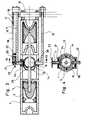
- Fig. 3 einen gegenüber Fig. 1 um 90° gedrehten Längsschnitt;
- Fig. 4 einen Querschnitt längs der Linie IV-IV in Fig. 3;
- Fig. 5 die Abwicklung der Zylinderwand und
- Fig. 6 die Abwicklung des Kolbenmantels.
- 1 shows a longitudinal section through the cylinder-piston arrangement.
- FIG. 2 shows a cross section along the line II-II in FIG. 1;
- 3 shows a longitudinal section rotated by 90 ° compared to FIG. 1;
- Fig. 4 is a cross section along the line IV-IV in Fig. 3;
- Fig. 5 the development of the cylinder wall and
- Fig. 6 the processing of the piston skirt.
Der Figurenbeschreibung ist voranzuschicken, daß die Zeichnungen rein schematischer Art sind und nur die prinzipielle Ausbildung, keine konstruktiven Einzelheiten vorgeben sollen.The description of the figures is to be forwarded that the drawings are of a purely schematic nature and are intended only to provide the basic training, no structural details.
In zwei koaxial zueinander angeordneten und miteinander in Verbindung stehenden Zylindern 1 und 2 befinden sich zwei Kolben 3 und 4, die über eine zentrale Kolbenstange 5 starr miteinander verbunden sind.Two
Beide Kolben sind jeweils doppelt wirkend ausgebildet, d. h., daß an beiden Stirnseiten ein Zylinderkopf 6, 7 bzw. 8, 9 angeordnet ist. Die Zylinderköpfe sind jeweils konvex zum Kolben hin gewölbt und ragen in den Totpunktstellungen des Kolbens in entsprechende Ausnehmungen desselben hinein.Both pistons are double-acting, i. That is, a
Um die hin- und hergehende Bewegung der Kolbenstange 5 in eine Drehbewegung der Kurbelwelle 10 umzuwandeln, dienen an sich bekannte Pleuel 11 und 12. Ihre Anordnung folgt aus Fig. 3. Sie laufen beidseits des Zylinders 2 und sind mit äußeren Schalen 13 und 14 eines auf der Kolbenstange 5 angeordneten Kugelgelenkes 15 verbunden.'Dieses Kugelgelenk 15 erlaubt der Kolbenstange 5 neben der hin- und hergehenden Hubbewegung eine Drehbewegung um die Kolbenstangenachse durchzuführen. Der Antrieb für diese Drehbewegung wird von der Kurbelwelle 10 abgeleitet. Im Ausführungsbeispiel erfolgt dies über zwei auf der Kurbelwelle angeordnete, gegeneinander versetzte Exzenterscheiben 16, 17, die über zwei Pleuel 18, 19 mit entsprechend versetzten Exzenterscheiben 20, 21 in Verbindung stehen, die ihrerseits auf dem einen Pleuel 11 gelagert sind. Die von der Kurbelwelle 10 auf die beiden letztgenannten Exzenterscheiben 20, 21 übertragene Drehbewegung wird über ein Untersetzungsgetriebe in Form zweier Zahnräder 22, 23 auf ein Winkelzahnrad 24 übertragen, das seinerseits mit einem auf der Kolbenstange 5 montierten Winkelzahnrad 25 kämmt. Auf diese Weise wird der Kolbenstange 5 und ihren beiden Kolben 3 und 4 während der Hubbewegung eine Rotationsbewegung überlagert. Diese Rotationsbewegung dient zum Steuern der Gaswechselvorgänge in den Zylindern, was nachfolgend näher beschrieben wird.In order to convert the reciprocating movement of the
Jeder Zylinder weist zweckmäßig zwei Einlaßöffnungen und zwei Auslaßöffnungen auf. Die Einlaßöffnungen wie auch die Auslaßöffnungen sind genau einander gegenüberliegend angeordnet, damit sich im Zylinder ein Ausgleich der Druckkräfte einstellen kann. Die Position der Ein- und Auslaßöffnungen ergibt sich aus dem Querschnitt in Fig. 2. Demnach hat der Zylinder 2 zwei einander gegenüberliegende Einlaßöffnungen 26 und 27 und zwei einander gegenüberliegende Auslaßöffnungen 28 und 29. Entsprechend sind auch die Ein- und Auslaßöffnungen am Zylinder 1 angeordnet. Mit diesen Öffnungen in der Zylinderwand korrespondieren Verbindungsbohrungen im Kolben in Abhängigkeit von dessen Hub- und Drehbewegung. Diese Verbindungsbohrungen erstrecken sich von der Kolbenwand zum Kolbenboden und sind ebenfalls einander gegenüberliegend angeordnet, wie dies in Fig. 1 im Fall des Kolbens 4 durch die Bezugszeichen 30 und 31 angedeutet ist. Versetzt hierzu und daher in der Zeichnung nicht sichtbar ist ein weiteres Paar gegenüberliegender Verbindungsbohrungen im Kolben 4 angeordnet, um den am anderen Kolbenboden befindlichen Brennraum mit den Einlaß- und Auslaßöffnungen 26 bis 29 zu verbinden.Each cylinder expediently has two inlet openings and two outlet openings. The inlet openings as well as the outlet openings are arranged exactly opposite one another so that a compensation of the pressure forces can occur in the cylinder. The position of the inlet and outlet openings results from the cross section in FIG. 2. Accordingly, the cylinder 2 has two
Ebenso ist auch der Kolben 3 von zwei Verbindungsbohrungen für den einen Brennraum und zwei Verbindungsbohrungen für den anderen Brennraum durchsetzt.Likewise, the
In dem zeichnerisch dargestellten Ausführungsbeispiel werden die Verbindungsbohrungen der Kolben abwechselnd vom Frischgas und vom Abgas durchströmt, wie dies nachfolgend näher erläutert wird. Es besteht jedoch durchaus die Möglichkeit, die Zahl der Verbindungsbohrungen zu verdoppeln, damit die eine Hälfte der Verbindungsbohrungen nur für das Frischgas, die andere Hälfte der Verbindungsbohrungen nur für das Abgas zur Verfügung steht und die raschen Richtungswechsel in der Gasströmung vermieden werden.In the exemplary embodiment shown in the drawing, the connecting bores of the pistons are alternately flowed through by fresh gas and exhaust gas, as will be explained in more detail below. However, it is possible to double the number of connection bores so that half of the connection bores are only available for fresh gas, the other half of the connection bores are only available for exhaust gas, and rapid changes in direction in the gas flow are avoided.
Die Fig. 5 und 6, die die Abwicklung des Zylinders bzw. des Kolbens zeigen, sind für den Fall dargestellt, daß jeder Brennraum über zwei spiegelbildlich im Kolben angeordnete Kanäle mit den Ein- bzw. Auslaßöffnungen der Zylinderwand korrespondiert. Das heißt, daß die Kanäle gleichzeitig an der Einlaßöffnung oder an der Auslaßöffnung oder an der Zylinderwand münden und sowohl vom Frischgas als auch vom Abgas durchströmt werden.5 and 6, which show the development of the cylinder and the piston, are shown in the event that each combustion chamber corresponds to the inlet and outlet openings of the cylinder wall via two channels arranged in mirror image in the piston. This means that the channels at the same time at the inlet opening or at the outlet opening or on the cylinder wall and both fresh gas and exhaust gas flow through.
Daraus folgt, daß nach einer Drehung des Kolbens um 180° alle vier Takte durchfahren sein müssen, daß dem Kolben pro Takt also eine Verdrehung von 45° zukommt. Da die Reihenfolge der Takte vorgegeben ist, nämlich Ansaugtakt, Verdichtungstakt, Arbeitstakt und Auspufftakt, muß die Einlaßöffnung unmittelbar auf die Auslaßöffnung folgen, während nach der Einlaßöffnung zwei Takte, also ein Umfangswinkel der Zylinderwand von 90°, frei bleiben muß, bis die nächste Auslaßöffnung folgt.It follows from this that after rotating the piston by 180 °, all four cycles must be completed, so that the piston is rotated by 45 ° per cycle. Since the sequence of the strokes is predetermined, namely intake stroke, compression stroke, working stroke and exhaust stroke, the intake opening must immediately follow the exhaust opening, while after the intake opening two strokes, i.e. a circumferential angle of the cylinder wall of 90 °, must remain free until the next exhaust opening follows.
Die Aufeinanderfolge der Ein- und Auslaßöffnungen ist in Fig. 5 in Abhängigkeit vom Umfangswinkel dargestellt, wobei die Bezugszeichen mit denen in Fig. 2 übereinstimmen.The sequence of the inlet and outlet openings is shown in FIG. 5 as a function of the circumferential angle, the reference symbols corresponding to those in FIG. 2.
Die Form der Ein- und Auslaßöffnungen in der Zylinderwand wird nach konstruktiven und strömungstechnischen Gesichtspunkten ausgewählt. Die in der Zeichnung dargestellte Rhombenform erlaubt den maximalen Öffnungsquerschnitt für den Ein- und Auslaß bei exakter Trennung des Ansaugtaktes vom Auspufftakt. Im allgemeinen wird jedoch eine Überschneidung der Öffnungszeiten zwischen Einlaß und Auslaß angestrebt. Daher wird in der Praxis die Kontur der Ein- und Auslaßöffnungen entsprechend von der Rhombenform abweichen. Eine Variante ist schematisch durch das gestrichelte Rechteck in den Ein- und Auslaßöffnungen 27 bzw. 29 angedeutet.The shape of the inlet and outlet openings in the cylinder wall is selected on the basis of design and fluid mechanics. The diamond shape shown in the drawing allows the maximum opening cross section for the intake and exhaust with exact separation of the intake stroke from the exhaust stroke. In general, however, the opening hours between outlet and outlet are overlapped. In practice, the contour of the inlet and outlet openings will therefore differ from the shape of the rhombus. A variant is indicated schematically by the dashed rectangle in the inlet and
Zur Verdeutlichung sei noch darauf hingewiesen, daß in Fig. 5 der obere und untere Blattrand jeweils etwa dem oberen bzw. unteren Zylinderrand entspricht. Die gestrichelte Sinuslinie gibt den Verlauf eines bestimmten Punktes des Kolbens bei seiner kombinierten Dreh- und Hubbewegung längs der Zylinderwand wieder.For the sake of clarity, it should also be pointed out that in FIG. 5 the upper and lower leaf margins are each approximately the same corresponds to the upper or lower cylinder edge. The dashed sine line shows the course of a certain point of the piston in its combined rotation and stroke movement along the cylinder wall.
Fig. 6 zeigt die entsprechende Abwicklung der Kolbenwand. Hinsichtlich der Lage der Kanäle, die in denselben Brennraum münden sollen, ist zunächst vorgegeben, daß diese um 180° versetzt sein müssen, um den erwünschten Ausgleich der Druckkräfte im Zylinder herbeizuführen.Fig. 6 shows the corresponding development of the piston wall. With regard to the position of the channels, which should open into the same combustion chamber, it is initially specified that they must be offset by 180 ° in order to bring about the desired compensation of the pressure forces in the cylinder.
Bezüglich der beiden in den anderen Brennraum mündenden Kanäle ist lediglich vorgegeben, daß diese gegenüber den vorgenannten Kanälen um 45° vor- oder rückversetzt sein müssen. Dadurch wird sichergestellt, daß beispielsweise beim Ansaugtakt des einen Verbrennungsraumes ein Verdichtungstakt oder ein Auspufftakt am gegenüberliegenden anderen Brennraum erfolgt.With regard to the two channels opening into the other combustion chamber, the only requirement is that they must be set forward or backward by 45 ° with respect to the aforementioned channels. This ensures that, for example, during the intake cycle of one combustion chamber, a compression cycle or an exhaust cycle takes place on the opposite other combustion chamber.
Beim Ausführungsbeispiel gemäß Fig. 6 sind die dem kurbelwellenseitigen Brennraum zugeordneten Kanäle entsprechend der Fig. 1 mit 30 und 31 bezeichnet, die dem gegenüberliegenden Brennraum zugeordneten, untereinander ebenfalls um 180° versetzten Kanäle mit 32 und 33.In the exemplary embodiment according to FIG. 6, the channels assigned to the combustion chamber on the crankshaft are designated 30 and 31 in accordance with FIG.
Der Verlauf der Kanäle im Kolben und ihre Mündung am Kolbenboden ist jeweils in gestrichelten Linien dargestellt, ebenfalls der nach innen eingehöhlte Kolbenboden 34 und 35.The course of the channels in the piston and their mouth on the piston crown is shown in broken lines, as is the
Beginnt man beispielsweise mit einem Ansaugtakt im kurbelwellenseitigen Brennraum, so ist der Kanal 30 durch die Zylinderwand verschlossen, da er zwischen der Auslaßöffnung 28 und der Einlaßöffnung 26 mündet, entsprechend der mit I angedeuteten Position in Fig. 5. Während des Ansaughubes wandert die Öffnung des Kanals 30 in die Einlaßöffnung 26 hinein und nimmt bei mittlerer Hublänge die mit II bezeichnete Position ein. Am Ende des Ansaugtaktes hat die Kanalöffnung 30 die Einlaßöffnung 26 passiert, wird also wieder von der Zylinderwand verschlossen. Dieser Zustand bleibt während des anschließenden Verdichtungshubes und des Arbeitshubes erhalten. Am Ende. des Arbeitshubes befindet sich die Öffnung des Kanals 30 in der mit IV bezeichneten Position, also kurz vor Erreichen der Auslaßöffnung 29. Nach Zurücklegen des halben Auspuffhubes nimmt sie die Position V ein, wobei volle Öffnung für das Auspuffgas gegeben ist, am Ende des Auspuffhubes die Position VI, wobei in der gewählten schematischen Darstellung die Öffnung wieder durch die Zylinderwand verschlossen ist. In dieser Position besteht jedoch durch die vorerwähnte Variation in der Form der Ein- und Auslaßöffnungen 26 bis 29 die Möglichkeit, daß sich die Ein-und Auslaßzeiten überschneiden.If one starts, for example, with an intake stroke in the combustion chamber on the crankshaft side, the
Entsprechend laufen die Takte beim gegenüberliegenden Brennraum ab, hier jedoch mit einem Takt Verspätung, da die zum unteren Brennraum gehörenden Kanäle 32 und 33 um 450, also um einen Takt, nach hinten versetzt sind.The cycles in the opposite combustion chamber run accordingly, but here with a cycle delay, since the
Im linken Teil von Fig. 6 ist zusätzlich angedeutet, daß die Kanäle 30 und 32 eine von außen nach innen laufende Scheidewand 30a bzw. 32a aufweisen können. Diese Scheidewand hat die Aufgabe, beim Übergang vom Auspufftakt zum Ansaugtakt sicherzustellen, daß sich die entgegengerichteten Gasströmungen möglichst wenig behindern. Diese Scheidewand kann selbstverständlich dann entfallen, wenn man die Zahl der Kanäle im Kolben verdoppelt, so daß getrennte Kanäle für das Ansaugen einerseits und für das Auspuffen andererseits zur Verfügung stehen.In the left part of FIG. 6 it is additionally indicated that the
Die vorangegangene Figurenbeschreibung erstreckt sich ausdrücklich nur auf ein spezielles Ausführungsbeispiel, ohne daß dadurch der Schutzumfang der Anmeldung beschränkt werden soll. Selbstverständlich gestattet dieses Ausführungsbeispiel zahlreiche konstruktive Abwandlungen.The preceding description of the figures expressly extends only to a specific exemplary embodiment, without the scope of protection of the application being restricted thereby. Of course, this embodiment allows numerous design modifications.
Beispielsweise braucht das Kugelgelenk 15 nicht unbedingt zwischen den beiden Kolben 3 und 4 angeordnet zu sein. Es besteht ebenso die Möglichkeit, es gegenüberliegend vom Zylinderkopf 6 anzuordnen und von dort die beiden Pleuel zur Kurbelwelle 10 zu führen.For example, the ball joint 15 does not necessarily have to be arranged between the two
Bezüglich der Positionierung der Zündkerzen bestehen ebenfalls verschiedene Möglichkeiten. Hier empfiehlt es sich, sie in der Zylinderwand vorzusehen, in dem Wandbereich, der am Ende des Verdichtungshubes von den Kanälen 30 und 31 überstrichen wird. Diese Positionierung bietet den Vorteil, daß die Zündkerzen in direkter Nachbarschaft zur Hauptgasmasse stehen.There are also various options with regard to the positioning of the spark plugs. Here it is advisable to provide them in the cylinder wall, in the wall area which is covered by the
Schließlich bietet sich noch die zweckmäßige Weiterbildung an, die von den beiden Pleueln 11 und 12 auf die Kolbenstange 5 übertragenen Querkräfte über eine Kugelrollführung aufzunehmen. Diese Kugelrollführung ist in Fig. 3 durch die Bezugszeichen 36 und 37 angedeutet. Sie besteht aus zwei Kugelschlitten, die in jeweils einem in Hubrichtung laufenden Längsschlitz des Zylindergehäuses angeordnet sind und die beiden Pleuel 11 und 12 quer zur Hubrichtung abstützen. Dadurch werden die Kolbendichtungen von den bisher üblichen Querkräften entlastet und können optimal auf ihre Dichtungsfunktion hin ausgelegt werden.Finally, there is also the expedient further development of absorbing the transverse forces transmitted from the two connecting
Es liegt im Rahmen der Erfindung, zum Erreichen hoher Verdichtungsverhältnisse, wie sie etwa bei Dieselmotoren gefordert werden, die konvexen Wölbungen der Zylinderköpfe 6, 7, 8 und 9 an dem nach innen ragenden Ende eines zylindrischen Zwischenstückes anzuordnen, so daß die Einbeulungen zunächst ein Stück mit konstantem Durchmesser nach innen laufen, ehe sie die in der Zeichnung dargestellte konvexe Wölbung annehmen. Am Übergang des zylindrischen Zwischenstückes zum gewölbten Bereich werden Dichtringe angeordnet, so daß sich der Brennraum verkleinert und das Verdichtungsverhältnis erhöht. Das Volumen des Brennraumes wird dabei im wesentlichen nur noch durch die Kanäle 30, 31 im Kolben bestimmt.It is within the scope of the invention, in order to achieve high compression ratios, such as those required in diesel engines, to arrange the convex curvatures of the
Die Abdichtung der Kanäle 30 bis 33 in den Kolben gegenüber der Zylinderwand erfolgt durch an sich bekannte Dichtleisten, die federnd gegen die Zylinderwand gedrückt werden.The
Konstruktive Änderungen der dargestellten Ausführungsbeispiele sind möglich, ohne dadurch den Schutzumfang der vorliegenden Anmeldung zu verlassen.Design changes to the illustrated exemplary embodiments are possible without thereby leaving the scope of protection of the present application.
Claims (11)
daß die Steuerung des Motors durch die Rotation der Kolben (3, 4) um ihre Längsachse erfolgt, wobei jeder Kolben (3, 4) zumindest eine Verbindungsbohrung (30, 31) von der Kolbenwand zum Kolbenboden aufweist, die in Abhängigkeit von der Kolbenbewegung mit der Einlaßöffnung (26, 27) oder mit der Auslaßöffnung (28, 29) des Zylinders (1, 2) korrespondiert und daß die Kolbenstange (5) über ein ihre Rotation gestattendes Gelenk (15) mit einer Kurbelwelle (10) verbunden ist, von der der Rotationsantrieb der Kolbenstange (5) abgeleitet ist.1. Internal combustion engine with at least two pistons arranged coaxially on a common piston rod and running in cylinders with inlet and outlet openings, characterized in that
that the motor is controlled by the rotation of the pistons (3, 4) about their longitudinal axis, each piston (3, 4) having at least one connecting bore (30, 31) from the piston wall to the piston crown, which is dependent on the piston movement corresponds to the inlet opening (26, 27) or to the outlet opening (28, 29) of the cylinder (1, 2) and that the piston rod (5) is connected to a crankshaft (10) via a joint (15) permitting its rotation, from which derives the rotary drive of the piston rod (5).
Priority Applications (1)
| Application Number | Priority Date | Filing Date | Title |
|---|---|---|---|
| AT82100777T ATE14151T1 (en) | 1981-05-09 | 1982-02-04 | COMBUSTION ENGINE. |
Applications Claiming Priority (2)
| Application Number | Priority Date | Filing Date | Title |
|---|---|---|---|
| DE3118452 | 1981-05-09 | ||
| DE19813118452 DE3118452A1 (en) | 1981-05-09 | 1981-05-09 | COMBUSTION ENGINE |
Publications (3)
| Publication Number | Publication Date |
|---|---|
| EP0065068A2 true EP0065068A2 (en) | 1982-11-24 |
| EP0065068A3 EP0065068A3 (en) | 1983-08-17 |
| EP0065068B1 EP0065068B1 (en) | 1985-07-03 |
Family
ID=6131893
Family Applications (1)
| Application Number | Title | Priority Date | Filing Date |
|---|---|---|---|
| EP82100777A Expired EP0065068B1 (en) | 1981-05-09 | 1982-02-04 | Internal-combustion engine |
Country Status (3)
| Country | Link |
|---|---|
| EP (1) | EP0065068B1 (en) |
| AT (1) | ATE14151T1 (en) |
| DE (1) | DE3118452A1 (en) |
Cited By (2)
| Publication number | Priority date | Publication date | Assignee | Title |
|---|---|---|---|---|
| BE1002092A4 (en) * | 1988-07-11 | 1990-06-26 | Growing Sprl | ROTARY MACHINE. |
| US7240645B2 (en) * | 2005-10-28 | 2007-07-10 | Reisser Heinz-Gustav A | Internal combustion engine |
Families Citing this family (2)
| Publication number | Priority date | Publication date | Assignee | Title |
|---|---|---|---|---|
| DE19515695C2 (en) * | 1994-10-20 | 1998-07-02 | Dirk Loehr | Piston-integrated control for a two-stroke or four-stroke internal combustion engine |
| DE102021129350A1 (en) | 2021-11-11 | 2023-05-11 | Alexander Alhaier | combustion engine |
Citations (7)
| Publication number | Priority date | Publication date | Assignee | Title |
|---|---|---|---|---|
| FR608682A (en) * | 1924-10-25 | 1926-07-31 | Distribution system for heat engine | |
| US2828906A (en) * | 1954-12-30 | 1958-04-01 | Hardman James Abraham | Engine |
| DE1451927A1 (en) * | 1965-01-11 | 1969-08-07 | Salmeri Saverio | Internal combustion engine with elicoidal shaft, couplings and rotating armature |
| GB1191556A (en) * | 1968-06-20 | 1970-05-13 | Noel Rodnight | Improvements in or relating to Two-Stroke Internal Combustion Engines. |
| DE1915109A1 (en) * | 1969-03-25 | 1970-10-01 | Gerd Schlautkoetter | Internal combustion engine with rotating piston |
| DE2215007A1 (en) * | 1972-03-28 | 1973-10-04 | Volkswagenwerk Ag | DRIVE MACHINE, IN PARTICULAR COMBUSTION MACHINE, WITH CRANKSHAFT-FREE POWER TRANSMISSION |
| DE3038673A1 (en) * | 1980-10-14 | 1982-05-27 | Wilfried 3176 Meinersen Schwant | Crankshaft-less IC engine - has tandem pistons rotated via cam skirts, with ports through pistons and output via shaft connecting pistons |
Family Cites Families (1)
| Publication number | Priority date | Publication date | Assignee | Title |
|---|---|---|---|---|
| US2327645A (en) * | 1941-09-08 | 1943-08-24 | Owen R Hughes | Internal combustion engine |
-
1981
- 1981-05-09 DE DE19813118452 patent/DE3118452A1/en not_active Withdrawn
-
1982
- 1982-02-04 EP EP82100777A patent/EP0065068B1/en not_active Expired
- 1982-02-04 AT AT82100777T patent/ATE14151T1/en not_active IP Right Cessation
Patent Citations (7)
| Publication number | Priority date | Publication date | Assignee | Title |
|---|---|---|---|---|
| FR608682A (en) * | 1924-10-25 | 1926-07-31 | Distribution system for heat engine | |
| US2828906A (en) * | 1954-12-30 | 1958-04-01 | Hardman James Abraham | Engine |
| DE1451927A1 (en) * | 1965-01-11 | 1969-08-07 | Salmeri Saverio | Internal combustion engine with elicoidal shaft, couplings and rotating armature |
| GB1191556A (en) * | 1968-06-20 | 1970-05-13 | Noel Rodnight | Improvements in or relating to Two-Stroke Internal Combustion Engines. |
| DE1915109A1 (en) * | 1969-03-25 | 1970-10-01 | Gerd Schlautkoetter | Internal combustion engine with rotating piston |
| DE2215007A1 (en) * | 1972-03-28 | 1973-10-04 | Volkswagenwerk Ag | DRIVE MACHINE, IN PARTICULAR COMBUSTION MACHINE, WITH CRANKSHAFT-FREE POWER TRANSMISSION |
| DE3038673A1 (en) * | 1980-10-14 | 1982-05-27 | Wilfried 3176 Meinersen Schwant | Crankshaft-less IC engine - has tandem pistons rotated via cam skirts, with ports through pistons and output via shaft connecting pistons |
Cited By (2)
| Publication number | Priority date | Publication date | Assignee | Title |
|---|---|---|---|---|
| BE1002092A4 (en) * | 1988-07-11 | 1990-06-26 | Growing Sprl | ROTARY MACHINE. |
| US7240645B2 (en) * | 2005-10-28 | 2007-07-10 | Reisser Heinz-Gustav A | Internal combustion engine |
Also Published As
| Publication number | Publication date |
|---|---|
| EP0065068A3 (en) | 1983-08-17 |
| DE3118452A1 (en) | 1982-12-02 |
| ATE14151T1 (en) | 1985-07-15 |
| EP0065068B1 (en) | 1985-07-03 |
Similar Documents
| Publication | Publication Date | Title |
|---|---|---|
| DE3224482C2 (en) | PISTON MACHINE | |
| DE849326C (en) | Hot gas engine with more than one cycle | |
| DE2731768A1 (en) | DRIVE UNIT FOR VEHICLES | |
| DE2047180C3 (en) | Piston engine | |
| DE19814870A1 (en) | Stroke piston internal combustion engine | |
| EP0065068B1 (en) | Internal-combustion engine | |
| WO1995034750A1 (en) | Internal-combustion engine, compressor or pump | |
| DE3331636A1 (en) | AGGREGATE CONSISTS OF A PISTON PISTON AND A GEARBOX | |
| DE3347859A1 (en) | Two-stroke piston internal combustion engine | |
| DE2901833A1 (en) | Two=stroke internal combustion engine - has piston in two sections of different diameters. for effective unidirectional scavenging | |
| EP0126464B1 (en) | Method of supplying combustion air to the combustion chamber of an internal-combustion engine | |
| EP0214255B1 (en) | Internal combustion engine | |
| DE345690C (en) | Air or gas pump | |
| DE4202640A1 (en) | High pressure fluid cleaning equipment - combines single cylinder pump with two=stroke IC engine | |
| DE2045759C3 (en) | Reciprocating heat engine for generating hydraulic energy | |
| DE2704006A1 (en) | Engine with two opposing pistons in cylinders - has gear mechanism so that inward stroke lengths of pistons are different | |
| DE3137471A1 (en) | Four-stroke internal combustion engine, especially for motor vehicles, with at least one pair of cylinders | |
| DE3137979A1 (en) | Lever piston engine | |
| DE19633174C2 (en) | Rotary piston power or work machine | |
| DE3320363A1 (en) | Four-stroke combustion engine without crankshaft | |
| DE609650C (en) | Two-stroke internal combustion engine with a cylinder divided into two consecutive spaces by a transverse wall | |
| DE2260454A1 (en) | COMBUSTION ENGINE | |
| DE244426C (en) | ||
| AT501274B1 (en) | Internal combustion engine, e.g. for vehicle, has sealing element rotating in operation to interact with spherical sealing surface | |
| DE2323009A1 (en) | COMBINATION PISTON AND FIVE-STROKE PRINCIPLE FOR CIRCULAR PISTON ENGINE WITH FULL CIRCLE IGNITION - OR FULL CIRCLE EFFECT - IN THE EVENT OF INTERNAL OR EXTERNAL COMBUSTION |
Legal Events
| Date | Code | Title | Description |
|---|---|---|---|
| PUAI | Public reference made under article 153(3) epc to a published international application that has entered the european phase |
Free format text: ORIGINAL CODE: 0009012 |
|
| AK | Designated contracting states |
Designated state(s): AT BE CH FR GB IT NL SE |
|
| 17P | Request for examination filed |
Effective date: 19830314 |
|
| PUAL | Search report despatched |
Free format text: ORIGINAL CODE: 0009013 |
|
| AK | Designated contracting states |
Designated state(s): AT BE CH FR GB IT LI NL SE |
|
| ITF | It: translation for a ep patent filed |
Owner name: ING. C. GREGORJ S.P.A. |
|
| GRAA | (expected) grant |
Free format text: ORIGINAL CODE: 0009210 |
|
| AK | Designated contracting states |
Designated state(s): AT BE CH FR GB IT LI NL SE |
|
| REF | Corresponds to: |
Ref document number: 14151 Country of ref document: AT Date of ref document: 19850715 Kind code of ref document: T |
|
| ET | Fr: translation filed | ||
| PG25 | Lapsed in a contracting state [announced via postgrant information from national office to epo] |
Ref country code: AT Effective date: 19860204 |
|
| PG25 | Lapsed in a contracting state [announced via postgrant information from national office to epo] |
Ref country code: SE Effective date: 19860205 |
|
| PG25 | Lapsed in a contracting state [announced via postgrant information from national office to epo] |
Ref country code: LI Effective date: 19860228 Ref country code: CH Effective date: 19860228 Ref country code: BE Effective date: 19860228 |
|
| PLBE | No opposition filed within time limit |
Free format text: ORIGINAL CODE: 0009261 |
|
| STAA | Information on the status of an ep patent application or granted ep patent |
Free format text: STATUS: NO OPPOSITION FILED WITHIN TIME LIMIT |
|
| 26N | No opposition filed | ||
| BERE | Be: lapsed |
Owner name: VOIGT E. D. Effective date: 19860228 |
|
| PG25 | Lapsed in a contracting state [announced via postgrant information from national office to epo] |
Ref country code: NL Effective date: 19860901 |
|
| NLV4 | Nl: lapsed or anulled due to non-payment of the annual fee | ||
| REG | Reference to a national code |
Ref country code: CH Ref legal event code: PL |
|
| GBPC | Gb: european patent ceased through non-payment of renewal fee | ||
| PG25 | Lapsed in a contracting state [announced via postgrant information from national office to epo] |
Ref country code: FR Free format text: LAPSE BECAUSE OF NON-PAYMENT OF DUE FEES Effective date: 19881028 |
|
| PG25 | Lapsed in a contracting state [announced via postgrant information from national office to epo] |
Ref country code: GB Effective date: 19881121 |
|
| REG | Reference to a national code |
Ref country code: FR Ref legal event code: ST |
|
| EUG | Se: european patent has lapsed |
Ref document number: 82100777.0 Effective date: 19861023 |