EP0065061A2 - Hydraulic piston track brake for braking railway vehicles - Google Patents
Hydraulic piston track brake for braking railway vehicles Download PDFInfo
- Publication number
- EP0065061A2 EP0065061A2 EP82100054A EP82100054A EP0065061A2 EP 0065061 A2 EP0065061 A2 EP 0065061A2 EP 82100054 A EP82100054 A EP 82100054A EP 82100054 A EP82100054 A EP 82100054A EP 0065061 A2 EP0065061 A2 EP 0065061A2
- Authority
- EP
- European Patent Office
- Prior art keywords
- damper
- bearing
- piston
- hydraulic
- rail
- Prior art date
- Legal status (The legal status is an assumption and is not a legal conclusion. Google has not performed a legal analysis and makes no representation as to the accuracy of the status listed.)
- Granted
Links
Images


Classifications
-
- B—PERFORMING OPERATIONS; TRANSPORTING
- B61—RAILWAYS
- B61K—AUXILIARY EQUIPMENT SPECIALLY ADAPTED FOR RAILWAYS, NOT OTHERWISE PROVIDED FOR
- B61K7/00—Railway stops fixed to permanent way; Track brakes or retarding apparatus fixed to permanent way; Sand tracks or the like
- B61K7/02—Track brakes or retarding apparatus
- B61K7/025—Retarders of the mushroom type
Definitions
- the piston rod is designed like a hook that projects over the mushroom-shaped head of the hydraulic unit. If necessary, the pneumatic cylinder can retract via the piston rod provided with a hook and lower the hydraulic unit of the piston brake against the lifting force of the hydraulic unit.
- This construction is extremely voluminous and constructively complex and is therefore to be rejected for this reason alone. It must be borne in mind that such a construction would be exposed to the harsh operating conditions in railway operation in all weather conditions, and is therefore very maintenance-intensive, and with an effort that can no longer be represented.
- a hydraulic piston rail brake according to the invention has a lowering device which can be extremely simple, for. B. as a one-sided hydraulic piston-cylinder unit that supports the damper. For example, by loading this piston-cylinder unit, the damper can be brought into its effective position, that is, upwards, while the damper is lowered when the hydraulic fluid is drained, so that the wagon wheel remains unaffected.
- a lowering device can be arranged coaxially to the damper, that is, below it, so that the entire device, that is to say hydraulic piston track brake with lowering device, is extremely compact.
- the connecting lines of the piston-cylinder units of the bearing shut-off devices are assigned.
- the individual bearings can be lowered to different degrees.
- the braking effect of the hydraulic piston rail brakes can also be changed.
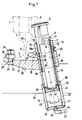
- the reference numeral 1 designates a wheel of a railroad car, not shown, which rolls on a conventional rail 2 with a vertical web 3 and foot 4.
- the reference numeral 5 designates the wheel flange of the wheel 1, which presses a head 6 of a hydraulic piston rail brake 7 downwards, that is to say centrally in the direction X, against a hydraulic damping force.
- the valves provided in the piston rail brake correspond to conventional designs of such hydraulic piston rail brakes and are therefore not necessary for understanding the invention and have therefore not been shown.
- the dampers 7 can be designed to be adjustable with regard to the response speed of the cars, so that only the so-called good runners are detected and braked by the dampers 7, while the bad runners are decelerated less or not at all.
- the speed and spacing of the railroad cars, not shown, can thus be regulated.
- each of the dampers 7 consists of two telescopically, ie variable in length; mutually guided telescopic parts 8, 9, which form a piston-cylinder unit. These telescopic parts 8 and 9 also take up the hydraulic damping medium and the valve devices, which also does not appear from the drawing.
- this head 6 has an approximately lenticular shape and is given an upward, approximately convex configuration by chamfering. In the embodiments according to FIGS. 1 and 2, this head 6 engages in a guide tube 12 and is coupled to it by means of a thread 13, but is detachable.
- the guide tube 12 also runs coaxially to the telescopic parts 8 and 9 and ends at a certain length distance - with the damper 7 pushed together - before the end of the telescopic part 9. As a result, the guide tube 12 moves together with the head 6 and the telescopic part 8 in the axial longitudinal direction of the damper 7.
- FIG. 1 shows in dashed lines the depressed damper 7, while the upper position of the damper 7, shown in full lines, shows the installed state in which the damper 7 is not acted on by a wheel 1.
- the telescopic parts 8 and 9 and the guide tube 12 are arranged coaxially in a bearing tube 14, which is assigned a lowering device 16 at its end facing the ground 15, which extends coaxially to the longitudinal axis of the damper 7 and thus also coaxially to the other tubes, which in the each will be described below.
- This lowering device 16 serves at the same time for mounting the damper 7 via a space hinge 17.
- This space hinge is formed in the embodiment shown in the drawing by a spherical cap which is firmly connected to the end face of the telescopic part 9 and rests in a shape-adapted bearing recess of the lowering device 16 .
- the guide tube 12 is guided in a longitudinally displaceable and tilt-free manner via two spaced-apart slide bearing rings 18 and 18a fastened in the bearing tube 14.
- a wiper seal 19 is arranged in the bearing tube 14 at the front, upper end of the bearing tube 14, which leads on the outer, cylindrical outer surface of the guide tube 12.
- the telescopic part 9, which is larger in diameter, can also be arranged at the top, while the telescopic part 8 is at the bottom, that is, where the telescopic part 9 is arranged in FIGS. 1 and 2.
- the space joint 17 instead of - as shown in Figures 1 and 2 - to be arranged below, above, z. B. in head 6 even articulated, z. B. in that the head 6 is made of a rubber-like elastomer.
- a space joint at the top and bottom that is in the area of the head 6 and in the area of the lowering device 16, in order to rule out tilting of the telescopic parts 8 and 9 when the force is applied eccentrically.
- the head 6 is advantageously arranged rotatably, so that when the wheel flange 5 strikes, the head can rotate as desired in both directions.
- the reference numeral 20 denotes a retaining tab, which has a bearing surface 21, which runs parallel to the underside of the foot 4 and on which the foot 4 rests.
- An upwardly open bearing or a bearing pan 22 is integrally connected to the retaining tab 20 in terms of material, on which the bearing tube 14 rests with an annular shoulder 24 with the interposition of a spacer ring 23.
- the bearing 22 has a cylindrical passage opening 25 through which the bearing tube 14 extends.
- a clamping projection 26 is connected, which is equipped with a bevel 27 adapted to the foot 4, which rests as much as possible on a corresponding bevel of the foot 4.
- a recess 28 is provided between the support surface 21 and the bearing 22, in which a part of the foot 4 of the rail 2 engages in a form-fitting manner.
- the holding tab 20 engages on the side opposite the bearing 22 so far beyond the foot area there that there is space for two through holes arranged at a distance from one another in the longitudinal direction of the rail 2, of which only one - 29 - can be seen from FIG. 2, while of the other through hole 30 in FIG. 5 only the center line was illustrated.
- the reference symbol of the through hole concerned was assigned to this center line.
- a screw engages through the through bores 29 and 30, of which only the screw 31 is illustrated in FIGS. 1 and 2. These screws each have a hammer-like head 32, which is positively inserted from below into a corresponding depression in the through hole 29 or 30 concerned and is thereby secured against rotation.
- a clamping piece 33 engages against the neck of the retaining tab 20 and against the adjacent foot part 4, so that after tightening the nuts 34 of the screws 31, the hydraulic piston rail brake is connected to the rail 2 by clamping, that is to say non-positively.
- the longitudinal axis 35 of the damper 7 extends at an acute angle to the longitudinal axis 36 of the rail 2.
- the head 6 can be reinforced in all cases or also made of steel. Furthermore, a shock absorbing body made of rubber or an elastomer with rubber-like properties can be provided under the head 6 in order to dampen noise.
- a bearing piston 41 is guided in a longitudinally displaceable and sealing manner, which on its side facing the telescopic part 9 has a concave recess 42 corresponding to the space joint 17, in which the spherical cap of the space joint 17 rests, so that the hydraulic damper between the head 6 and Bearing piston 41 is supported.
- the end face 40 forms a stop for the bearing piston 41 during its axial displacement in the direction Y, while the displacement path of the bearing piston 41 in the opposite direction X is limited by a welded end wall 43.
- This end wall has a central connection opening 44 with a connection fitting 45 for supplying a suitable pressure medium, in particular hydraulic fluid, into the cylinder space 46 via the feed line 47.
- the annular shoulder 39 which forms the stop for the bearing piston 41 in the direction of displacement Y, is formed by a circlip which is arranged in the inner cylinder wall of the bearing tube 14.
- a further difference from the embodiment according to FIG. 1 can be seen in the fact that the bearing tube 14 and the short tube piece 37 are made in one piece in terms of material, such that the bearing tube 40 has been extended downwards by an amount which is approximately the axial length of the tube piece 37 corresponds.
- the bearing piston 41 abuts the upper stop, that is to say the annular shoulder 39. This is ensured by the pressure medium pressure, in particular hydraulic pressure, prevailing in the cylinder space 46.
- the cylinder chamber 46 is filled with pressure oil via the feed line 47 and by a shut-off element, not shown, for. B. shut off by a slide which is arranged in the feed line 47.
- the piston track brake 7 is ready to brake again when the cylinder chamber 41 is filled with pressure oil from a central hydraulic supply by actuation of the shut-off element, not shown, which results in a corresponding displacement of the bearing piston 41 in the Y direction up to the annular shoulder 39. This also raises the telescopic parts 8 and 9 until the hydraulic damper has returned to its functional position.
- a larger number of hydraulic piston rail brakes 7 are connected to a feed line 47.
- the number may be much greater than from F ig. 4 emerges.
- a central, electromagnetic shut-off device 48 which can be controlled from a central switching point ! can, e.g. B. the entire group of piston rail brakes connected to the supply line 47 are relieved of pressure such that the inflow to a tank 49 is released. If the piston track brakes are rolled over by wheels, the dampers together with the bearing pistons 41 - as described above - are moved downward. The pressure oil in the relevant cylinder chamber 46 is displaced into the feed line 47. This can result in the pressure oil pushing another bearing piston 41 upwards, that is to say in the Y direction, so that the individual dampers change their position in accordance with the rollover process. If several hydraulic dampers are rolled over or this is the path of least resistance for the pressure oil, it also flows off to the storage tank 49.
- a suitable pressure medium source in particular a motor-driven pump, is connected to line 50.
- the reference numeral 51 denotes a so-called entry group of tracks, while 52 denotes a discharge hill and 53 the so-called distribution zone, which is followed by a direction group of tracks at 54.
- Hydraulic piston track brakes with lowering devices are preferably arranged at the beginning of the directional tracks 54.
Abstract
Description
Alle bisher bekanntgewordenen hydraulischen Kolbengleisbremsen zum Abbremsen von Eisenbahnwagen erzeugen beim Abbremsen von langen Wagengruppen in den Verzögerungsstrecken einen Rückstau in der Verteilzone. Für einen gut laufenden sogenannten Nachläufer besteht dann die Gefahr eines Eckstoßes, was zum Entgleisen führen kann. Es ist deshalb unter Umständen notwendig, die Abdrückgeschwindigkeit und damit die Leistungsfähigkeit der Ablaufanlagen zu reduzieren, damit eine lange Wagengruppe zunächst die Verteilzone freigibt. Dieser Nachteil tritt insbesondere bei langen unbeladenen Wagengruppen auf, weil die Verzögerungsstrecke für beladene Wagen dimensioniert ist und die leichte Wagengruppe sehr früh die von den hydraulischen Kolbenbremsen vorgegebene Auslaufgeschwindigkeit erreicht. Der relativ lange Rest der Wagengruppe blockiert dann die Verteilzone mit der Sollauslaufgeschwindigkeit der hydraulischen Kolbengleisbremsen (König, Helmut in ETR (25) 9 - 1976 S. 551 bis 561). In dem vorerwähnten Aufsatz äußert sich der Verfasser dahingehend, daß eine Absenkbarkeit der gesamten hydraulischen Kolbengleisbremse aus wirtschaftlichen Gründen kaum realisierbar sei. Auch Versuche mit zum Stande der Technik zählenden hydraulischen Kolbengleisbremsen scheinen diese Auffassung zu bestätigen. Die Anmelderin ist sich allerdings nicht im klaren darüber, ob es sich bei den ihr bekanntgewordenen Versuchen um geheime Versuche, oder aber um offenkundige Vorbenutzungshandlungen handelt, weshalb diesbezüglich vorsorglich Vorbehalte hinsichtlich der Zugehörigkeit zum Stande der Technik angemeldet werden. Bei diesen Versuchen hat man parallel zur Hydraulikeinheit der Kolbengleisbremse an der Halterung der Bremse einen Pneumatikzylinder angeordent. Die Kolbenstange ist am Ende wie ein Haken ausgebildet, der über den pilzförmigen Kopf der Hydraulikeinheit ragt. Bei Bedarf kann der Pneumatikzylinder über die mit einem Haken versehene Kolbenstange einfahren und die Hydraulikeinheit der Kolbenbremse gegen Aufstellkraft der Hydraulikeinheit absenken. Diese Konstruktion baut außerordentlich voluminös und konstruktiv aufwendig und ist deshalb schon aus diesem Grunde abzulehnen. Dabei muß bedacht werden, daß eine solche Konstruktion den rauhen Betriebsbedingungen im Bahnbetrieb bei allen Witterungseinflüssen ausgesetzt sein würde, und somit sehr unterhaltungsaufwendig ist, und zwar mit einem Aufwand, der sich nicht mehr vertreten läßt.All previously known hydraulic piston rail brakes for braking railway carriages generate a backlog in the distribution zone when braking long car groups in the deceleration sections. For a well-running so-called follow-up there is a risk of a corner kick, which can lead to derailment. It may therefore be necessary to reduce the pull-off speed and thus the performance of the drainage systems so that a long group of wagons initially clears the distribution zone. This disadvantage occurs in particular in the case of long, unloaded wagon groups, because the delay line for dimensioned wagons is dimensioned and the light wagon group reaches the run-out speed specified by the hydraulic piston brakes very early on. The relatively long remainder of the wagon group then blocked the distribution zone with the target outlet speed of the hydraulic piston rail brakes (König, Helmut in ETR (25) 9 - 1976 pp. 551 to 561). In the above-mentioned article, the author states that it is almost impossible to lower the entire hydraulic piston rail brake for economic reasons. Tests with hydraulic piston rail brakes, which belong to the state of the art, also seem to confirm this view. However, the applicant is not clear whether the attempts that have come to her notice are secret attempts or are obvious prior uses, which is why, as a precautionary measure, reservations regarding the state of the art are being made. In these experiments, a pneumatic cylinder was arranged parallel to the hydraulic unit of the piston track brake on the brake bracket. At the end, the piston rod is designed like a hook that projects over the mushroom-shaped head of the hydraulic unit. If necessary, the pneumatic cylinder can retract via the piston rod provided with a hook and lower the hydraulic unit of the piston brake against the lifting force of the hydraulic unit. This construction is extremely voluminous and constructively complex and is therefore to be rejected for this reason alone. It must be borne in mind that such a construction would be exposed to the harsh operating conditions in railway operation in all weather conditions, and is therefore very maintenance-intensive, and with an effort that can no longer be represented.
Der Erfindung liegt die Aufgabe zugrunde, eine hydraulische Kolbengleisbremse zum Abbremsen von Eisenbahnwagen der im Gattungsbegriff bezeichneten Art auf konstruktiv einfache Weise so auszugestalten, daß sie je nach Bedarf ganz oder teilweise unwirksam bzw. ausgeschaltet werden kann.The invention has for its object to design a hydraulic piston rail brake for braking railroad cars of the type described in the generic term in a structurally simple manner so that it can be completely or partially ineffective or switched off as required.
Die Aufgabe wird durch die im Patentanspruch 1 wiedergegebenen Merkmale gelöst.The object is achieved by the features set out in
Eine hydraulische Kolbengleisbremse gemäß der Erfindung weist eine Absenkvorrichtung auf, die außerordentlich einfach ausgebildet sein kann, z. B. als einseitig hydraulisch beaufschlagbare Kolben-Zylinder-Einheit, die den Dämpfer abstützt. Zum Beispiel läßt sich durch Beaufschlagen dieser Kolben-Zylinder-Einheit der Dämpfer in seine wirksame Stellung, also nach oben bringen, während beim Ablassen der Hydraulikflüssigkeit der Dämpfer abgesenkt wird, so daß das Wagenrad unbeeinflußt bleibt. Eine solche Absenkvorrichtung läßt sich koaxial zum Dämpfer, also unter diesem, anordnen, so daß die gesamte Vorrichtung, also hydraulische Kolbengleisbremse mit Absenkvorrichtung außerordentlich kompakt baut.A hydraulic piston rail brake according to the invention has a lowering device which can be extremely simple, for. B. as a one-sided hydraulic piston-cylinder unit that supports the damper. For example, by loading this piston-cylinder unit, the damper can be brought into its effective position, that is, upwards, while the damper is lowered when the hydraulic fluid is drained, so that the wagon wheel remains unaffected. Such a lowering device can be arranged coaxially to the damper, that is, below it, so that the entire device, that is to say hydraulic piston track brake with lowering device, is extremely compact.
Es besteht sogar die Möglichkeit, für den Dämpfer einen Serienartikel, z. B. aus der Automobilbranche, zu verwenden, der sich wie die Kolben-Zylinder-Einheit, die die Absenkvorrichtung bildet, in einem Rohr abstützt, so daß das die Absenkvorrichtung bildenden Lager, ebenso wie der Dämpfer, gut geschützt sind. Infolgedessen braucht die gesamte Vorrichtung nicht mehr an Wartungsaufwand als dies ohnehin von üblichen hydraulischen Kolbengleisbremsen bekannt ist.There is even the possibility of a series article for the damper, e.g. B. from the automotive industry, which is supported like the piston-cylinder unit that forms the lowering device, in a tube, so that the lowering device forming the bearing, as well as the damper, are well protected. As a result, the entire device does not need more maintenance than that of conventional hydraulic ones Piston track brakes is known.
Hydraulische Kolbengleisbremsen mit einem die Absenkvorrichtung bildenden, hydraulisch betätigbaren Lager können an eine zentrale Hydraulikversorgung angeschlossen werden. Mit den in der Hydraulik heute üblichen Schalt- und Steuergliedern können einzelne hydraulische Kolbengleisbremsen oder ganze Gruppen einer Verzögerungsstrecke unabhängig voneinander wirksam oder unwirksam ferngeschaltet werden. Damit kann einer mehr oder weniger langen bzw. mehr oder weniger schweren Wagengruppe die notwendige Anzahl von hydraulischen Kolbengleisbremsen wirksam zugeschaltet werden, damit kein gefährlicher Rückstau in der Verteilzone entsteht. Auch sind Eckstöße nicht mehr zu befürchten.Hydraulic piston rail brakes with a hydraulically actuated bearing forming the lowering device can be connected to a central hydraulic supply. With the switching and control elements common today in hydraulics, individual hydraulic piston rail brakes or entire groups of a delay line can be independently or effectively switched off. This means that the necessary number of hydraulic piston rail brakes can be effectively connected to a more or less long or more or less heavy wagon group, so that there is no dangerous backflow in the distribution zone. There are no longer any worries about corner kicks.
Da die Informationen über ein Wagengruppengewicht und Wagengruppenlänge zentral für den ganzen Rangierbahnhof hinter dem Ablaufberg erfaßt werden können und diese in die jeweiligen Richtungsgleise durchgeschaltet werden, ist der zusätzliche Steuerungsaufwand gering.Since the information about a wagon group weight and wagon group length can be recorded centrally for the entire marshalling yard behind the drain mountain and these are switched through to the respective direction tracks, the additional control effort is low.
Infolgedessen ist es bei Anwendung der Erfindung möglich, eine Verzögerungsstrecke mit optimaler Belegungszeit zu schaffen, ohne auf die Vorteile der hydraulischen Kolbengleisbremse mit einer integrierten Geschwindigkeitssteuerung und ohne externe Bremsenergiezuführung verzichten zu müssen.As a result, when using the invention, it is possible to create a delay line with an optimal occupancy time, without having to forego the advantages of the hydraulic piston rail brake with an integrated speed control and without an external brake energy supply.
Ein weiterer, bemerkenswerter Vorteil ist darin zu sehen, daß sich die erfindungsgemäß vorgeschlagene hydraulische Kolbengleisbremse mit der Absenkhydraulik ohne Probleme auch an hydraulischen Kolbengleisbremsen mit einem Kühler anbauen läßt. Durch die einfache und originelle Art der Absenkhydraulik lassen sich beide Vorteile zusammen verwirklichen.Another remarkable advantage is the fact that the hydraulic piston track brake proposed according to the invention with the lowering hydraulics can also be easily fitted to hydraulic piston track brakes with a cooler. Due to the simple and original type of lowering hydraulics, both advantages can be realized together.
Bei Ausgestaltung gemäß Patentanspruch 2 ergibt sich eine besonders einfache, raumsparende Konstruktion mit günstiger Krafteinleitung in das die Absenkvorrichtung bildende Lager.In the embodiment according to
Das gilt auch für die Lösung nach Patentanspruch 3, bei welcher das Lager für den Dämpfer einen fliegend gelagerten Kolben aufweist, der sich einseitig gegen Hydraulikdruck abstützt, so daß durch Entlasten des mit Hydraulikdruck beaufschlagbaren Zylinderraumes der Kolben in Axialrichtung des Dämpfers verstellbar ist, womit eine entsprechende Verstellung des mit dem Wagenrad in Berührung kommenden Kopfes verbunden ist.This also applies to the solution according to
Von besonderem Vorteil sind die Ausführungsformen nach den Patentansprüchen 4 und 5, zumal solche hydraulischen Kolbengleisbremsen zusätzlich noch den Vorteil aufweisen, daß der Dämpfer in einem Führungsrohr praktisch allseitig geschützt angeordnet ist. Dadurch wird der Wartungsaufwand solcher Kolbengleisbremsen weiterhin herabgesetzt und/oder die Funktionsfähigkeit erhöht.Of particular advantage are the embodiments according to
Des weiteren brauchen bei einer erfindungsgemäßen hydraulischen Kolbengleisbremse auch nicht mehr - wie bisher - Halter durch Schraubenbolzen, die mit Durchgangsbohrungen den Schienensteg durchgreifen, an diesem befestigt zu werden. Vielmehr ist es bei der Erfindung möglich, den Schienensteg unbeschädigt zu lassen, da die hydraulische Kolbengleisbremse am Schienenfuß angeklemmt wird. Damit können die teueren und wegen Schwächung des Schienensteges auch nachteiligen Bohrungen bei der Erfindung vollständig eingespart werden.Furthermore, in the case of a hydraulic piston rail brake according to the invention, holders no longer need to be fastened to it by screw bolts which pass through the rail web with through holes, as was previously the case. Rather, it is possible with the invention to leave the rail web undamaged since the hydraulic piston rail brake is clamped on the rail foot. Thus the expensive and because of weakening of the S chien ridge and adverse drilling of the invention will be fully saved can.
Bei der Ausführungsform nach Patentanspruch 6 sind alle Kolbengleisbremsen einer Gruppe an eine Sammelleitung angeschlossen. Diese Sammelleitung kann mit einem geeigneten Tank in Verbindung stehen, der z. B. durch ein Mehrwegeventil zu- und abschaltbar ist. Beim Überfahren von Kolbengleisbremsen, deren Lager abgesenkt oder vollständig entlastet sind, werden die Lager über die Köpfe und den Dämpfer nach unten gedrückt, wobei sie Hydraulikflüssigkeit in die gemeinsame Sammelleitung verdrängen. Dadurch kann es an anderer Stelle zu einem Hochschieben von hydraulischen Dämpfern kommen, was unproblematisch ist. Sollten zufälligerweise zahlreiche Dämpfer, deren Lager entlastet oder teilweise nach unten gefahren sind gleichzeitig von Wagenrädern überrollt werden, so fließt die verdrängte Hydraulikflüssigkeit über die Sammelleitung in den Tank ab.In the embodiment according to
Gemäß Patentanspruch 7 sind den Anschlußleitungen der Kolben-Zylinder-Einheiten der Lager Absperrorgane zugeordnet.According to
Gemäß Patentanspruch 8 können die einzelnen Lager unterschiedlich weit abgesenkt werden. Dadurch kann, über den Weg gesehen, die Bremswirkung der hydraulischen Kolbengleisbremsen gleichfalls verändert werden.According to
In der Zeichnung ist die Erfindung - teils schematisch - an mehreren Ausführungsbeispielen veranschaulicht. Es zeigen
- Fig. 1 eine hydraulische Kolbengleisbremse an einer Schiene gemäß der Erfindung im Längsschnitt;
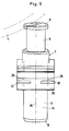
- Fig. 2 eine weitere Ausführungsform, ebenfalls im Längsschnitt;
- Fig. 3 einen Lageplan einer Ablaufanlage;
- Fig. 4 ein hydraulisches Schaltschema und
- Fig. 5 eine Teil-Seitenansicht zu Fig. 1 bzw. 2.
- 1 shows a hydraulic piston track brake on a rail according to the invention in longitudinal section.
- Fig. 2 shows another embodiment, also in longitudinal section;
- 3 shows a site plan of a drainage system;
- Fig. 4 is a hydraulic circuit diagram and
- 5 shows a partial side view of FIGS. 1 and 2.
Das Bezugszeichen 1 bezeichnet ein Rad eines nicht dargestellten Eisenbahnwagen, das auf einer üblichen Schiene 2 mit senkrechtem Steg 3 und Fuß 4 rollt. Dabei bezeichent das Bezugszeichen 5 den Spurkranz des Rades 1, der einen Kopf 6 einer hydraulischen Kolbengleisbremse 7 beim Überrollen nach unten, also zentrisch in Richtung X gegen eine hydraulische Dämpfungskraft drückt. Die in der Kolbengleisbremse vorgesehenen Ventile entsprechen üblichen Konstruktionen solcher hydraulischen Kolbengleisbremsen und sind deshalb zum Verständnis der Erfindung nicht notwendig und daher auch nicht dargestellt worden.The
Bei sämtlichen aus der Zeichnung ersichtlichen Ausführungsformen können die Dämpfer 7 hinsichtlich der Ansprechgeschwindigkeit der Wagen einstellbar ausgebildet sein, so daß nur die sogenannten Gutläufer von den Dämpfern 7 erfaßt und abgebremst werden, während die Schlechtläufer weniger oder überhaupt nicht verzögert werden. Damit kann also die Geschwindigkeit und Abstandshaltung der nicht dargestellten Eisenbahnwagen geregelt werden.In all the embodiments shown in the drawing, the
Jeder der Dämpfer 7 besteht bei den dargestellten Ausführungsformen aus zwei teleskopartig, also längenveränderlich in- ; einander geführten Teleskopteilen 8, 9, die eine Kolben-Zylinder-Einheit bilden. Diese Teleskopteile 8 und 9 nehmen auch - was gleichfalls aus der Zeichnung nicht hervorgeht - das hydraulische Dämpfungsmedium und die Ventilvorrichtungen auf.In the illustrated embodiments, each of the
Deutlich läßt die Fig. 1 erkennen, daß das im Durchmesser kleiner bemessene Teleskopteil 8 bei dieser Ausführungsform am oberen, d. h. dem Rad 1 zugekehrten Ende des Dämpfers 7 angeordnet ist und hier über einen Sprengring 11 oder in sonstiger, geeigneter Weise lösbar mit dem Kopf 6 gekuppelt ist. Dieser Kopf 6 ist bei der Ausführungsform nach den Figuren 1 und 2 annähernd linsenförmig ausgebildet und erhält durch eine Anfasung eine nach oben gerichtete, etwa konvexe Ausgestaltung. Dieser Kopf 6 greift bei den Ausführungsformen nach den Figuren 1 und 2 in ein Führungsrohr 12 und ist mit diesem durch Gewinde 13 fest, aber lösbar, gekuppelt. Auch das Führungsrohr 12 verläuft koaxial zu den Teleskopteilen 8 und 9 und endet in einem gewissen Längenabstand - bei zusammengeschobenem Dämpfer 7 - vor dem Ende des Teleskopteiles 9. Dadurch bewegt sich das Führungsrohr 12 zusammen mit dem Kopf 6 und dem Teleskopteil 8 in Achslängsrichtung des Dämpfers 7. Die Fig. 1 zeigt in gestrichelten Linien den eingedrückten Dämpfer 7, während die obere, vollständig mit ausgezogenen Linien dargestellte Stellung des Dämpfers 7 den Einbauzustand zeigt, bei welchem der Dämpfer 7 nicht durch ein Rad 1 beaufschlagt ist.1 clearly shows that the
Die Teleskopteile 8 und 9 und das Führungsrohr 12 sind koaxial in einem Lagerrohr 14 angeordnet, dem an seinem dem Erdreich 15 zugekehrten Ende eine Absenkvorrichtung 16 zugeordnet ist, die koaxial zur Längsachse des Dämpfers 7 und damit auch koaxial zu den anderen Rohren verläuft, die im einzelnen weiter unten noch beschrieben werden. Diese Absenkvorrichtung 16 dient gleichzeitig zur Lagerung des Dämpfers 7 über ein Raumgelenk 17. Dieses Raumgelenk wird bei den aus der Zeichnung dargestellten Ausführungsform durch eine Kugelkalotte gebildet, die mit der Stirnfläche des Teleskopteils 9 fest verbunden ist und in einer formmäßig angepaßten Lagerausnehmung der Absenkvorrichtung 16 ruht.The
Das Führungsrohr 12 ist über zwei mit Abstand zueinander angeordnete, im Lagerrohr 14 befestigte Gleitlagerringe 18 bzw. 18a längsverschieblich und verkantungsfrei geführt. Außerdem ist am stirnseitigen, oberen Ende des Lagerrohres 14 eine Abstreifdichtung 19 im Lagerrohr 14 angeordnet, die sich auf der äußeren, zylindrischen Mantelfläche des Führungsrohres 12 führt.The
Das im Durchmesser größer bemessene Teleskopteil 9 kann auch i oben angeordnet sein, während das Teleskopteil 8 sich unten befindet, also dort, wo in den Figuren 1 und 2 das Teleskopteil 9 angeordnet ist. Außerdem ist es in diesem Falle möglich, ! das Raumgelenk 17 statt - wie in den Figuren 1 und 2 dargestellt ist - unten, oben anzuordnen, z. B. in Kopf 6 selbst raumgelenkig auszubilden, z. B. dadurch, daß der Kopf 6 aus einem kautschukartigen Elastomere hergestellt wird. Des weiteren ist es denkbar, oben und unten, also im Bereich des Kopfes 6 und im Bereich der Absenkvorrichtung 16 je ein Raumgelenk anzuordnen, um ein Verkanten der Teleskopteile 8 und 9 bei exzentrischer Krafteinleitung auszuschließen.The
Des weiteren ist der Kopf 6 vorteilhafterweise drehbar angeordnet, so daß beim Auftreffen des Spurkranzes 5 sich der Kopf beliebig in beiden Richtungen drehen kann.Furthermore, the
Mit dem Bezugszeichen 20 ist eine Haltelasche bezeichnet, die eine parallel zur Unterseite des Fußes 4 verlaufende Auflagefläche 21 aufweist, auf der Fuß 4 aufruht. Mit der Haltelasche 20 ist materialmäßig einstückig ein nach oben offenes Lager oder eine Lagerpfanne 22 verbunden, auf der das Lagerrohr 14 unter Zwischenschaltung eines Distanzringes 23 mit einer Ringschulter 24 aufruht. Das Lager 22 weist eine zylindrische Druchgangsöffnung 25 auf, durch die das Lagerrohr 14 hindurchgreift.The
Mit dem Lager 22 ist ein Klemmansatz 26 verbunden, der mit einer dem Fuß 4 angepaßten Schräge 27 ausgerüstet ist, die möglichst satt auf einer entsprechenden Schräge des Fußes 4 aufruht. Im übrigen ist zwischen der Auflagefläche 21 und dem Lager 22 eine Aussparung 28 vorgesehen, in die ein Teil des Fußes 4 der Schiene 2 formschlüssig eingreift.With the
Wie insbesondere die Figuren 1 und 2 erkennen lassen, greift die Haltelasche 20 auf der dem Lager 22 gegenüberleigenden Seite so weit über den dortigen Fußbereich hinaus, daß hier Platz für zwei in Längsrichtung der Schiene 2 mit Abstand zueinander angeordneten Durchgangsbohrungen gegeben ist, von der nur eine - 29 - aus Fig. 2 ersichtlich ist, während von der anderen Durchgangsbohrung 30 in Fig. 5 lediglich die Mittellinie veranschaulicht wurde. Dieser Mittellinie wurde das Bezugszeichen der betreffenden Durchgangsbohrung zugeordnet. Durch die Durchgangsbohrungen 29 und 30 greift jeweils eine Schraube, von der lediglich die Schraube 31 in Fig. 1 und 2 veranschaulicht ist. Diese Schrauben weisen je einen hammerartigen Kopf 32 auf, der sich von unten formschlüssig in eine entsprechende Einsenkung der betreffenden Durchgangsbohrung 29 bzw. 30 einlegt und dadurch gegen Verdrehen gesichert ist. Von oben greift ein Klemmstück 33 gegen den Ansatz der Haltelasche 20 und gegen den benachbarten Fußteil 4, so daß nach Anziehen der Muttern 34 der Schrauben 31 die hydraulische Kolbengleisbremse durch Klemmen, also kraftschlüssig mit der Schiene 2 verbunden ist. Dabei verläuft die Längsachse 35 des Dämpfers 7 unter einem spitzen Winkel zur Längsachse 36 der Schiene 2.As can be seen in particular in FIGS. 1 and 2, the holding
Der Kopf 6 kann in allen Fällen armiert sein oder ebenfalls aus Stahl bestehen. Des weiteren kann unter dem Kopf 6 ein Stoßdämpfungskörper aus Gummi oder einem Elastomere mit gummiartigen Eigenschaften vorgesehen sein, um Geräusche zu dämpfen.The
Bei der aus Fig. 1 und 2 ersichtlichen Ausführungsform ist auf das Lagerrohr 14 ein kurzes Rohrstück 37 mittels Gewinde 38 aufgeschraubt worden, das sich mit einer Ringschulter 39 gegen die Stirnfläche 40 des Lagerrohres 14 anlegt und durch nicht näher dargestellte Dichtungen abgedichtet ist.In the embodiment shown in FIGS. 1 and 2, a short piece of
In dem zylindrischen Rohrstück 37 ist ein Lagerkolben 41 längsverschieblich und dichtend geführt, der an seiner dem Teleskopteil 9 zugekehrten Seite eine dem Raumgelenk 17 entsprechende konkave Ausnehmung 42 aufweist, in der die Kugelkalotte des Raumgelenks 17 ruht, so daß der hydraulische Dämpfer zwischen Kopf 6 und Lagerkolgen 41 abgestützt ist.In the
Die Stirnfläche 40 bildet einen Anschlag für den Lagerkolben 41 bei dessen Axialverschiebung in Richtung Y, während der Verschiebeweg des Lagerkolbens 41 in entgegengesetzter Richtung X durch eine eingeschweißte Stirnwand 43 begrenzt ist. Diese Stirnwand besitzt eine zentrische Anschlußöffnung 44 mit einer Anschlußarmatur 45 zum Zuführen eines geeigneten Druckmittels, insbesondere Hydraulikflüssigkeit, in den Zylinderraum 46, über die Zuleitung 47.The end face 40 forms a stop for the
Bei der Ausführungsform nach Fig. 2 sind für Teile gleicher Funktion die gleichen Bezugszeichen verwendet worden.In the embodiment according to FIG. 2, the same reference numerals have been used for parts with the same function.
Im Unterschied zur Ausführungsform nach Fig. 1 wird die Ringschulter 39, die den Anschlag für den Lagerkolben 41 in Verschieberichtung Y bildet durch einen Seegering gebildet, der in der inneren Zylinderwandung des Lagerrohres 14 angeordnet ist.In contrast to the embodiment according to FIG. 1, the
Ein weiterer Unterschied zur Ausführungsform nach Fig. 1 ist darin zu sehen, daß Lagerrohr 14 und das kurze Rohrstück 37 materialmäßig einstückig ausgebildet sind, derart, daß das Lagerrohr 40 nach unten hin verlängert worden ist um einen Betrag, der etwa der axialen Länge des Rohrstückes 37 entspricht.A further difference from the embodiment according to FIG. 1 can be seen in the fact that the bearing
Während des normalen Betriebs liegt der Lagerkolben 41 am oberen Anschlag, also an der Ringschulter 39, an. Das wird durch den im Zylinderraum 46 herrschenden Druckmitteldruck, insbesondere Hydraulikdruck, sichergestellt. Der Zylinderraum 46 wird zu diesem Zweck über die Zuleitung 47 mit Drucköl gefüllt und durch ein nicht dargestelltes Absperrorgan, z. B. durch einen Schieber, der in der Zuleitung 47 angeordnet ist, abgesperrt.During normal operation, the
Beim Überfahren der hydraulischen Kolbengleisbremse 7 stützen sich die Teleskopteile 8 und 9 auf dem verstellbaren Lager 41 ab. Der hydraulische Dämpfer, also die Teleskopteile 8 und 9, müssen dem überrollenden Rad 5 folgend einen vollen Arbeitshub ausführen und dabei eine entsprechende Bremsarbeit leisten.When driving over the hydraulic
Soll die Bremswirkung der betreffenden hydraulischen Kolbengleisbremse gezielt aufgehoben oder gemildert werden, z. B. beim Abbremsen von langen Wagengruppen, dann wird der Zylinderraum 46 durch Öffnen des nicht dargestellten Absperrorgans entspannt. Wird nunmehr die betreffende hydraulische Kolbengleisbremse überfahren, so findet der hydraulsiche Dämpfer keine Abstütztung mehr und schiebt das nachgiebige Widerlager 41 in die in den Figuren 1 und 2 gestrichelt dargestellte untere Lage. Hierbei führt der hydraulische Dämpfer keinen Arbeitshub auf. Das überrollende Rad 5 hat lediglich das Führungsrohr 12 mit dem Teleskopteil 8, 9 und dem nachgiebigen Widerlager 41 gegen geringen Reibungs- und Strömungswiderstand zu verschieben.If the braking effect of the hydraulic piston track brake in question is specifically canceled or mitigated, e.g. B. when braking long car groups, then the
Die Kolbengleisbremse 7 wird wieder bremsbereit, wenn durch Betätigen des nicht dargestellten Absperrorgans der Zylinderraum 41 von einer zentralen Hydraulikversorgung mit Drucköl gefüllt wird, was eine entsprechende Verschiebung des Lagerkolbens 41 in Richtung Y bis zur Ringschulter 39 zur Folge hat. Dadurch werden auch die Teleskopteile 8 und 9 angehoben, bis der hydraulische Dämpfer wieder in seiner Funktionsstellung gelangt ist.The
Bei der Ausführungsform nach Fig. 4 ist an einer Zuleitung 47 eine größere Anzahl von hydraulischen Kolbengleisbremsen 7 angeschlossen. In der Praxis kann die Anzahl wesentlich größer sein als dies aus Fig. 4 hervorgeht.In the embodiment according to FIG. 4, a larger number of hydraulic
Durch ein zentrales, elektromagnetisches Absperrorgan 48, das von einer zentralen Schaltstelle aus gesteuert werden ! kann, kann z. B. die gesamte Gruppe der an die Zuleitung 47 angeschlossenen Kolbengleisbremsen druckentlastet werden, derart, daß der Zufluß zu einem Tank 49 freigegeben ist. Werden die Kolbengleisbremsen von Rädern überrollt, so werden die Dämpfer zusammen mit den Lagerkolben 41 - wie oben beschrieben wurde - nach unten verschoben. Dabei wird das in dem betreffenden Zylinderraum 46 befindliche Drucköl in die Zuleitung 47 verdrängt. Dadurch kann es vorkommen, daß das Drucköl einen anderen Lagerkolben 41 nach aufwärts, also in Richtung Y, schiebt, so daß die einzelnen Dämpfer entsprechend des Überrollvorganges ihre Lage verändern. Sollten mehrere hydraulische Dämpfer überrollt werden oder dies der Weg des geringsten Widerstandes für das Drucköl sein, so fließt es auch zum Lagertank 49 ab. Through a central, electromagnetic shut-off
An die Leitung 50 ist eine geeignete Druckmittelquelle, insbesondere eine motorisch angetriebene Pumpe, angeschlossen.A suitable pressure medium source, in particular a motor-driven pump, is connected to
In Fig. 3 ist mit dem Bezugszeichen 51 eine sogenannte Einfahrgruppe von Gleisen bezeichnet, während 52 einen Ablaufberg beezichnet und 53 die sogenannte Verteilzone, an die sich bei 54 eine Richtungsgruppe von Gleisen anschließt.In Fig. 3, the
Hydraulische Kolbengleisbremsen mit Absenkvorrichtungen werden vorzugsweise am Beginn der Richtungsgleise 54 angeordnet.Hydraulic piston track brakes with lowering devices are preferably arranged at the beginning of the directional tracks 54.
Die in der Beschreibung und in den Patentansprüchen beschriebenen und in der Zeichnung dargestellten Merkmale können sowohl einzeln als auch in beliebigen Kombinationen für die Verwirklichung der Erfindung wesentlich sein.The features described in the description and in the patent claims and shown in the drawing can be essential both individually and in any combination for realizing the invention.
- 1 Rad1 wheel
- 2 Schiene2 rails
- 3 Steg3 bridge
- 4 Fuß4 feet
- 5 Spurkranz5 wheel flange
- 6 Kopf6 head
- 7 Kolbengleisbremse, Dämpfer7 piston rail brake, damper
- 8 Teleskopteil8 telescopic part
- 99
- 10 - 10 -
- 11 Sprengring11 snap ring
- 12 Führungsrohr12 guide tube
- 13 Gewinde13 threads
- 14 Lagerrohr14 bearing tube
- 15 Erdreich15 soil
- 16 Absenkvorrichtung16 lowering device
- 17 Raumgelenk17 space joint
- 18 Gleitlagerring18 plain bearing ring
- 18a " 18a "
- 19 Abstreifdichtung19 Wiper seal
- 20 Haltelasche20 retaining tab
- 21 Auflagefläche21 contact surface
- 22 Lager, Lagerpfanne22 bearings, bearing pan
- 23 Distanzring23 spacer ring
- 24 Ringschulter24 ring shoulder
- 25 Durchgangsöffnung25 through opening
- 26 Klemmansatz26 clamping attachment
- 27 Schräge27 slant
- 28 Aussparung28 recess
- 29 Durchgangsbohrung29 through hole
- 30 "30 "
- 31 Schraube31 screw
- 32 Kopf32 head
- 33 Klemmstück33 clamping piece
- 34 Mutter34 mother
- 35 Längsachse35 longitudinal axis
- 36 "36 "
- 37 kurzes Rohrstück37 short pipe section
- 38 Gewinde38 threads
- 39 Ringschulter39 ring shoulder
- 40 Stirnfläche40 end face
- 41 Lagerkolben, Widerlager41 bearing pistons, abutments
- 42 konkave Ausnehmung42 concave recess
- 43 Stirnwand43 end wall
- 44 Anschlußöffnung44 connection opening
- 45 Anschlußarmatur45 connection fitting
- 46 Zylinderraum46 cylinder space
- 47 Zuleitung47 supply line
- 48 Absperrorgan48 shut-off device
- 49 Tank49 tank
- 50 Druckmittelquelle50 pressure medium source
- 51 Einfahrgruppe51 entry group
- 52 Ablaufberg52 drain mountain
- 53 Verteilzone53 distribution zone
- 54 Richtungsgruppe54 Direction group
- X VerschieberichtungX direction of displacement
- Y "Y "
Claims (8)
Priority Applications (1)
| Application Number | Priority Date | Filing Date | Title |
|---|---|---|---|
| AT82100054T ATE10078T1 (en) | 1981-05-19 | 1982-01-07 | HYDRAULIC PISTON TRACK BRAKE FOR BRAKING RAILWAY CARS. |
Applications Claiming Priority (2)
| Application Number | Priority Date | Filing Date | Title |
|---|---|---|---|
| DE3119861A DE3119861C2 (en) | 1981-05-19 | 1981-05-19 | Hydraulic piston rail brake for braking railway wagons |
| DE3119861 | 1981-05-19 |
Publications (3)
| Publication Number | Publication Date |
|---|---|
| EP0065061A2 true EP0065061A2 (en) | 1982-11-24 |
| EP0065061A3 EP0065061A3 (en) | 1982-12-29 |
| EP0065061B1 EP0065061B1 (en) | 1984-10-31 |
Family
ID=6132678
Family Applications (1)
| Application Number | Title | Priority Date | Filing Date |
|---|---|---|---|
| EP82100054A Expired EP0065061B1 (en) | 1981-05-19 | 1982-01-07 | Hydraulic piston track brake for braking railway vehicles |
Country Status (3)
| Country | Link |
|---|---|
| EP (1) | EP0065061B1 (en) |
| AT (1) | ATE10078T1 (en) |
| DE (2) | DE3119861C2 (en) |
Cited By (3)
| Publication number | Priority date | Publication date | Assignee | Title |
|---|---|---|---|---|
| DE3604113A1 (en) * | 1986-02-10 | 1987-08-13 | Siemens Ag | Device for controlling the speed of rail vehicles in shunting systems |
| GB2199919A (en) * | 1987-01-20 | 1988-07-20 | Nat Supply Co | Landing device |
| WO1999030950A1 (en) * | 1997-12-13 | 1999-06-24 | Tiefenbach Gmbh | Rail brake device |
Families Citing this family (2)
| Publication number | Priority date | Publication date | Assignee | Title |
|---|---|---|---|---|
| US4535872A (en) * | 1981-10-06 | 1985-08-20 | Dowty Hydraulic Units Limited | Retarders suitable for wagon speed control and having means for holding them in their operative condition |
| DE102016212654A1 (en) | 2016-07-12 | 2018-01-18 | Stabilus Gmbh | A rail brake damper |
Citations (7)
| Publication number | Priority date | Publication date | Assignee | Title |
|---|---|---|---|---|
| FR847462A (en) * | 1938-06-16 | 1939-10-10 | Brasseur | Braking system and possibly stopping sedans or other vehicles traveling on the railway |
| DE1183530B (en) * | 1960-05-01 | 1964-12-17 | Dowty Mining Equipment Ltd | Control device for influencing the speed of freely running rail vehicles |
| DE1937113A1 (en) * | 1969-07-22 | 1971-02-04 | Konrad Grebe | Control device for influencing the speed of free-running rail vehicles |
| DE2052774A1 (en) * | 1969-10-29 | 1971-07-22 | Bourcier de Carbon, Christian Marie Lucien Genf (Schweiz) | Device for regulating the height of vehicles with hydropneumatic shock absorbers |
| DE2165064A1 (en) * | 1970-12-29 | 1972-07-06 | Girling Ltd., Birmingham, Warwickshire (Grossbritannien) | Motorcycle suspension |
| DE2507337A1 (en) * | 1973-02-28 | 1976-09-09 | Dowty Mining Equipment Ltd | DEVICE AND METHOD FOR SPEED CONTROL OF RAILWAY CARRIAGES |
| GB2032028A (en) * | 1978-06-22 | 1980-04-30 | Clarke C W | Rail-mounted hydraulic retarder |
Family Cites Families (1)
| Publication number | Priority date | Publication date | Assignee | Title |
|---|---|---|---|---|
| DE1605349A1 (en) * | 1967-02-28 | 1971-03-11 | Kloeckner Werke Ag | Device for regulating the speed of rolling railroad cars |
-
1981
- 1981-05-19 DE DE3119861A patent/DE3119861C2/en not_active Expired
-
1982
- 1982-01-07 EP EP82100054A patent/EP0065061B1/en not_active Expired
- 1982-01-07 DE DE8282100054T patent/DE3261081D1/en not_active Expired
- 1982-01-07 AT AT82100054T patent/ATE10078T1/en active
Patent Citations (7)
| Publication number | Priority date | Publication date | Assignee | Title |
|---|---|---|---|---|
| FR847462A (en) * | 1938-06-16 | 1939-10-10 | Brasseur | Braking system and possibly stopping sedans or other vehicles traveling on the railway |
| DE1183530B (en) * | 1960-05-01 | 1964-12-17 | Dowty Mining Equipment Ltd | Control device for influencing the speed of freely running rail vehicles |
| DE1937113A1 (en) * | 1969-07-22 | 1971-02-04 | Konrad Grebe | Control device for influencing the speed of free-running rail vehicles |
| DE2052774A1 (en) * | 1969-10-29 | 1971-07-22 | Bourcier de Carbon, Christian Marie Lucien Genf (Schweiz) | Device for regulating the height of vehicles with hydropneumatic shock absorbers |
| DE2165064A1 (en) * | 1970-12-29 | 1972-07-06 | Girling Ltd., Birmingham, Warwickshire (Grossbritannien) | Motorcycle suspension |
| DE2507337A1 (en) * | 1973-02-28 | 1976-09-09 | Dowty Mining Equipment Ltd | DEVICE AND METHOD FOR SPEED CONTROL OF RAILWAY CARRIAGES |
| GB2032028A (en) * | 1978-06-22 | 1980-04-30 | Clarke C W | Rail-mounted hydraulic retarder |
Cited By (3)
| Publication number | Priority date | Publication date | Assignee | Title |
|---|---|---|---|---|
| DE3604113A1 (en) * | 1986-02-10 | 1987-08-13 | Siemens Ag | Device for controlling the speed of rail vehicles in shunting systems |
| GB2199919A (en) * | 1987-01-20 | 1988-07-20 | Nat Supply Co | Landing device |
| WO1999030950A1 (en) * | 1997-12-13 | 1999-06-24 | Tiefenbach Gmbh | Rail brake device |
Also Published As
| Publication number | Publication date |
|---|---|
| ATE10078T1 (en) | 1984-11-15 |
| DE3261081D1 (en) | 1984-12-06 |
| EP0065061A3 (en) | 1982-12-29 |
| EP0065061B1 (en) | 1984-10-31 |
| DE3119861A1 (en) | 1982-12-09 |
| DE3119861C2 (en) | 1984-04-05 |
Similar Documents
| Publication | Publication Date | Title |
|---|---|---|
| DE102011113561A1 (en) | Hubkielvorrichtung | |
| DE4305192A1 (en) | ||
| DE2344691A1 (en) | SPRING STORAGE CYLINDERS, IN PARTICULAR FOR RAIL VEHICLE COMPRESSED AIR BRAKE SYSTEMS | |
| DE1605307A1 (en) | Brake assembly for the rolling stock of railways | |
| DE2755032A1 (en) | TRACK BRAKE FOR RAILWAYS | |
| DE3236340A1 (en) | TRACK BRAKE FOR BRAKING RAILWAYS | |
| DE1920311U (en) | DEVICE FOR VEHICLES WITH HYDRAULIC BRAKES FOR CHANGING THE BRAKING FORCE ON THE VEHICLE'S WHEELS DEPENDING ON THE WHEEL LOAD. | |
| EP0065061B1 (en) | Hydraulic piston track brake for braking railway vehicles | |
| DE1630567C3 (en) | Chain tensioning device for caterpillar vehicles | |
| DE1058854B (en) | Damping device for impacts of large amplitude for the axle suspension of vehicles | |
| DE3604520A1 (en) | TRACK BRAKE TO CONTROL THE SPEED OF RAILWAYS | |
| DE2507337C2 (en) | Control device for influencing the speed of free-running rail vehicles | |
| EP1669267A2 (en) | Trailer support apparatus | |
| DE1934482A1 (en) | Railroad car | |
| DE3031173C2 (en) | Hydraulic piston rail brake for braking railway wagons | |
| DE3533216C2 (en) | ||
| DE8114838U1 (en) | HYDRAULIC PISTON TRACK BRAKE FOR BRAKING RAILWAYS | |
| EP0049446B1 (en) | Hydraulic piston track brake for braking railway trucks | |
| DE3642776A1 (en) | STACKING VEHICLE WITH A SWIVEL-MOUNTED LIFTING DEVICE | |
| DE2255435A1 (en) | DEVICE FOR GRINDING RAILS | |
| DE2120593C3 (en) | Braking device, in particular a hydraulic handbrake for railroad cars | |
| EP2871117B1 (en) | Commercial vehicle chassis with adjustable length | |
| DE4339670C2 (en) | Locking system for changing devices for use in trucks and element for use in such a system | |
| DE19526950C1 (en) | Guide device for vehicle locked onto rails | |
| DE3321384C1 (en) | Method of braking with brake trolleys in underground coal mining, and brake trolley for carrying out this method |
Legal Events
| Date | Code | Title | Description |
|---|---|---|---|
| PUAI | Public reference made under article 153(3) epc to a published international application that has entered the european phase |
Free format text: ORIGINAL CODE: 0009012 |
|
| PUAL | Search report despatched |
Free format text: ORIGINAL CODE: 0009013 |
|
| 17P | Request for examination filed |
Effective date: 19820115 |
|
| AK | Designated contracting states |
Designated state(s): AT BE CH DE FR GB IT LU NL SE |
|
| AK | Designated contracting states |
Designated state(s): AT BE CH DE FR GB IT LI LU NL SE |
|
| GRAA | (expected) grant |
Free format text: ORIGINAL CODE: 0009210 |
|
| AK | Designated contracting states |
Designated state(s): AT BE CH DE FR GB IT LI LU NL SE |
|
| PG25 | Lapsed in a contracting state [announced via postgrant information from national office to epo] |
Ref country code: SE Effective date: 19841031 Ref country code: NL Effective date: 19841031 Ref country code: IT Free format text: LAPSE BECAUSE OF FAILURE TO SUBMIT A TRANSLATION OF THE DESCRIPTION OR TO PAY THE FEE WITHIN THE PRESCRIBED TIME-LIMIT;WARNING: LAPSES OF ITALIAN PATENTS WITH EFFECTIVE DATE BEFORE 2007 MAY HAVE OCCURRED AT ANY TIME BEFORE 2007. THE CORRECT EFFECTIVE DATE MAY BE DIFFERENT FROM THE ONE RECORDED. Effective date: 19841031 Ref country code: FR Free format text: THE PATENT HAS BEEN ANNULLED BY A DECISION OF A NATIONAL AUTHORITY Effective date: 19841031 Ref country code: BE Effective date: 19841031 |
|
| REF | Corresponds to: |
Ref document number: 10078 Country of ref document: AT Date of ref document: 19841115 Kind code of ref document: T |
|
| REF | Corresponds to: |
Ref document number: 3261081 Country of ref document: DE Date of ref document: 19841206 |
|
| PG25 | Lapsed in a contracting state [announced via postgrant information from national office to epo] |
Ref country code: AT Effective date: 19850107 |
|
| PG25 | Lapsed in a contracting state [announced via postgrant information from national office to epo] |
Ref country code: LU Free format text: LAPSE BECAUSE OF NON-PAYMENT OF DUE FEES Effective date: 19850131 Ref country code: LI Effective date: 19850131 Ref country code: CH Effective date: 19850131 |
|
| NLV1 | Nl: lapsed or annulled due to failure to fulfill the requirements of art. 29p and 29m of the patents act | ||
| PLBE | No opposition filed within time limit |
Free format text: ORIGINAL CODE: 0009261 |
|
| STAA | Information on the status of an ep patent application or granted ep patent |
Free format text: STATUS: NO OPPOSITION FILED WITHIN TIME LIMIT |
|
| EN | Fr: translation not filed | ||
| REG | Reference to a national code |
Ref country code: CH Ref legal event code: PL |
|
| PG25 | Lapsed in a contracting state [announced via postgrant information from national office to epo] |
Ref country code: DE Effective date: 19851001 |
|
| 26N | No opposition filed | ||
| GBPC | Gb: european patent ceased through non-payment of renewal fee | ||
| PG25 | Lapsed in a contracting state [announced via postgrant information from national office to epo] |
Ref country code: GB Effective date: 19881121 |