EP0064996B1 - Motor vehicle wheel suspension - Google Patents
Motor vehicle wheel suspension Download PDFInfo
- Publication number
- EP0064996B1 EP0064996B1 EP81903107A EP81903107A EP0064996B1 EP 0064996 B1 EP0064996 B1 EP 0064996B1 EP 81903107 A EP81903107 A EP 81903107A EP 81903107 A EP81903107 A EP 81903107A EP 0064996 B1 EP0064996 B1 EP 0064996B1
- Authority
- EP
- European Patent Office
- Prior art keywords
- wheel
- suspension
- vehicle
- compliance device
- longitudinal displacement
- Prior art date
- Legal status (The legal status is an assumption and is not a legal conclusion. Google has not performed a legal analysis and makes no representation as to the accuracy of the status listed.)
- Expired
Links
- 239000000725 suspension Substances 0.000 title claims abstract description 91
- 238000006073 displacement reaction Methods 0.000 claims abstract description 31
- 230000010355 oscillation Effects 0.000 claims abstract description 26
- 230000000694 effects Effects 0.000 claims abstract description 7
- 239000003381 stabilizer Substances 0.000 claims description 7
- 229920002635 polyurethane Polymers 0.000 claims description 3
- 239000004814 polyurethane Substances 0.000 claims description 3
- 239000000463 material Substances 0.000 claims 1
- 230000005540 biological transmission Effects 0.000 description 2
- 238000004519 manufacturing process Methods 0.000 description 1
- 239000002184 metal Substances 0.000 description 1
- 238000012986 modification Methods 0.000 description 1
- 230000004048 modification Effects 0.000 description 1
- 230000036316 preload Effects 0.000 description 1
- 230000000750 progressive effect Effects 0.000 description 1
- 239000012858 resilient material Substances 0.000 description 1
- 230000035939 shock Effects 0.000 description 1
- 230000001629 suppression Effects 0.000 description 1
Images
Classifications
-
- B—PERFORMING OPERATIONS; TRANSPORTING
- B60—VEHICLES IN GENERAL
- B60G—VEHICLE SUSPENSION ARRANGEMENTS
- B60G3/00—Resilient suspensions for a single wheel
- B60G3/18—Resilient suspensions for a single wheel with two or more pivoted arms, e.g. parallelogram
- B60G3/20—Resilient suspensions for a single wheel with two or more pivoted arms, e.g. parallelogram all arms being rigid
- B60G3/202—Resilient suspensions for a single wheel with two or more pivoted arms, e.g. parallelogram all arms being rigid having one longitudinal arm and two parallel transversal arms, e.g. dual-link type strut suspension
-
- B—PERFORMING OPERATIONS; TRANSPORTING
- B60—VEHICLES IN GENERAL
- B60G—VEHICLE SUSPENSION ARRANGEMENTS
- B60G21/00—Interconnection systems for two or more resiliently-suspended wheels, e.g. for stabilising a vehicle body with respect to acceleration, deceleration or centrifugal forces
- B60G21/02—Interconnection systems for two or more resiliently-suspended wheels, e.g. for stabilising a vehicle body with respect to acceleration, deceleration or centrifugal forces permanently interconnected
- B60G21/04—Interconnection systems for two or more resiliently-suspended wheels, e.g. for stabilising a vehicle body with respect to acceleration, deceleration or centrifugal forces permanently interconnected mechanically
- B60G21/05—Interconnection systems for two or more resiliently-suspended wheels, e.g. for stabilising a vehicle body with respect to acceleration, deceleration or centrifugal forces permanently interconnected mechanically between wheels on the same axle but on different sides of the vehicle, i.e. the left and right wheel suspensions being interconnected
- B60G21/055—Stabiliser bars
- B60G21/0551—Mounting means therefor
-
- B—PERFORMING OPERATIONS; TRANSPORTING
- B60—VEHICLES IN GENERAL
- B60G—VEHICLE SUSPENSION ARRANGEMENTS
- B60G7/00—Pivoted suspension arms; Accessories thereof
-
- B—PERFORMING OPERATIONS; TRANSPORTING
- B60—VEHICLES IN GENERAL
- B60G—VEHICLE SUSPENSION ARRANGEMENTS
- B60G2200/00—Indexing codes relating to suspension types
- B60G2200/10—Independent suspensions
- B60G2200/14—Independent suspensions with lateral arms
- B60G2200/141—Independent suspensions with lateral arms with one trailing arm and one lateral arm only
-
- B—PERFORMING OPERATIONS; TRANSPORTING
- B60—VEHICLES IN GENERAL
- B60G—VEHICLE SUSPENSION ARRANGEMENTS
- B60G2200/00—Indexing codes relating to suspension types
- B60G2200/10—Independent suspensions
- B60G2200/14—Independent suspensions with lateral arms
- B60G2200/142—Independent suspensions with lateral arms with a single lateral arm, e.g. MacPherson type
- B60G2200/1422—Independent suspensions with lateral arms with a single lateral arm, e.g. MacPherson type the lateral arm being resilient
-
- B—PERFORMING OPERATIONS; TRANSPORTING
- B60—VEHICLES IN GENERAL
- B60G—VEHICLE SUSPENSION ARRANGEMENTS
- B60G2202/00—Indexing codes relating to the type of spring, damper or actuator
- B60G2202/10—Type of spring
- B60G2202/13—Torsion spring
- B60G2202/132—Torsion spring comprising a longitudinal torsion bar and/or tube
-
- B—PERFORMING OPERATIONS; TRANSPORTING
- B60—VEHICLES IN GENERAL
- B60G—VEHICLE SUSPENSION ARRANGEMENTS
- B60G2204/00—Indexing codes related to suspensions per se or to auxiliary parts
- B60G2204/40—Auxiliary suspension parts; Adjustment of suspensions
- B60G2204/43—Fittings, brackets or knuckles
- B60G2204/4307—Bracket or knuckle for torsional springs
-
- B—PERFORMING OPERATIONS; TRANSPORTING
- B60—VEHICLES IN GENERAL
- B60G—VEHICLE SUSPENSION ARRANGEMENTS
- B60G2204/00—Indexing codes related to suspensions per se or to auxiliary parts
- B60G2204/80—Interactive suspensions; arrangement affecting more than one suspension unit
- B60G2204/82—Interactive suspensions; arrangement affecting more than one suspension unit left and right unit on same axle
-
- B—PERFORMING OPERATIONS; TRANSPORTING
- B60—VEHICLES IN GENERAL
- B60G—VEHICLE SUSPENSION ARRANGEMENTS
- B60G2204/00—Indexing codes related to suspensions per se or to auxiliary parts
- B60G2204/80—Interactive suspensions; arrangement affecting more than one suspension unit
- B60G2204/83—Type of interconnection
- B60G2204/8302—Mechanical
Definitions
- This invention relates to motor vehicle wheel suspensions, and is of particular utility in independent steerable front wheel suspensions.
- critical wobble speed typically about 40 km/h (25 m.p.h.), about 88 km/h (55 m.p.h.) and about 136 km/h (85 m.p.h.)
- critical wobble speed typically about 40 km/h (25 m.p.h.), about 88 km/h (55 m.p.h.) and about 136 km/h (85 m.p.h.)
- the base frequency of this oscillation is of the order of 10 Hz with harmonics at approximately 5 and 18 Hz.
- these oscillations are transmitted through a steering linkage and steering mechanism to the steering wheel, and this causes discomfort to the driver.
- this solution requires additional operation during vehicle manufacture and rebalancing of the wheels in service as the tyres wear or are replaced or the balancing weights are lost.
- the present invention utilises a novel compliance device in combination with appropriate modification of the geometry of the suspension to reduce, not the oscillations, but the transmission of them to the steering wheel or in the case of a rear suspension, to the body.
- GB-A-987670 discloses a motor vehicle front suspension in which a road wheel is connected to a suspension arm by a compliance device which permits the wheel to move forwardly and rearwardly. This device provides a resilient connection of the wheel to the vehicle and is intended to reduce noise, vibration and harshness transmitted to the sprung part of the vehicle from the road surface.
- the novel compliance device of the invention permits limited forward and rearward displacement of the wheel spindle relative to the vehicle. Its longitudinal resistance for such limited forward and rearward displacement must be proportionately less than that required to overcome the friction in the steering gear linkage.
- the steering link and suspension arm have in many vehicles approximately constituted a parallelogram (that is the pivot points of the steering link and suspension arm and their respective connections to the wheel are at the four corners of the parallelogram) so that as the wheel is displaced longitudinally as permitted by the compliance device the road wheel is not turned.
- the steering link and suspension arm have not constituted a parallelogram. This has not been to achieve any special result but has been dictated by package requirements.
- the invention may be used in a rear wheel suspension as well as in a front wheel suspension.
- the invention is based on a motor vehicle suspension having the following features: a compliance device permits limited longitudinal displacement of the wheel relative to the vehicle so that the wheel can be displaced forwardly and rearwardly by rotating out of balance forces when the wheel rotates at a critical wobble speed.
- the geometry of the suspension is such that it causes the wheel to toe in for forward longitudinal displacement of the wheel and to toe out for rearwardly longitudinal displacement of the wheel by substantially the same amount for a given longitudinal displacement as the toe in and toe out movements which would be caused for the same longitudinal dis-I placement at said critical wobble speed by said out of balance forces in the absence of any restraint of angular movements of the wheel about a substantially vertical axis, whereby the effect of the out of balance forces on the unsprung part of the vehicle is reduced.
- an out of balance force on the road wheel causes it to oscillate at a high frequency about a vertical axis (the king pin), the out of balance force exerts a forward or rearward longitudinal force on the suspension linkage which causes the wheel to move as permitted by the compliance device forwardly or rearwardly relative to the sprung part of the vehicle; and the idiosyncratic geometry of the suspension arm and the steering link is such that when this oscillation takes place the steering link is displaced substantially at right angles to the axis so that axial displacement of the steering link which would otherwise occur and cause movement of the steering wheel is reduced or eliminated.
- the compliance device is formed with resilient material which becomes harder and permits less displacement as the frequency of the road wheel oscillations increases. In effect therefore a degree of progressive change in the compliance device is provided to match it approximately to the amplitude of the "shimmy" oscillations.
- the invention is particularly suitable for use with Macpherson front suspensions, in which the compliance device is used to connect the suspension arm to a stabiliser (or anti-roll) bar or tie rod.
- the invention can however be incorporated in other forms of suspensions for example the double wishbone or short/long arm suspension.
- the term "suspension arm" includes the two links of the double wishbone or short/long arm suspensions.
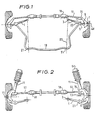
- the independent front suspension shown in Figure 1 is of the type known as a Macpherson suspension. It comprises at each side of the vehicle a suspension arm 1 pivotally mounted in the sprung part of the vehicle about a generally longitudinal axis 53 by a pivot bush 3 which permits limited forward and rearward movement of the outer end 5 of the suspension arm 1 about a generally vertical axis passing through the bush 3.
- a wheel spindle 7 is connected by a suspension ball joint 9 to a king pin carried by the suspension arm 1 and is fixed to the lower end of a conventional suspension strut 11.
- the upper end of the strut 11 is fixed to the sprung part of the vehicle by an upper mount 50 in the conventional way, the casing of the strut being rotatable relatively to the piston of the strut so that the wheel spindle can rotate about a king pin axis defined by the upper mount 50 and the suspension ball joint 9.
- the wheel spindle 7 has a conventional stub axle 48 on which a road wheel is rotatably mounted.
- a steering arm 13 extends rearwardly from the wheel spindle 7 and is connected by a steering ball joint 15 to a steering link 17.
- the latter in turn is connected by a ball joint 18 and a conventional rack and pinion steering mechanism to the steering wheel (not shown).
- the steering link 17 As the steering wheel is turned, the steering link 17 is moved along its axis. This turns the wheel spindle 7 about the king pin axis and so turns the road wheel.
- Movement of the suspension arm 1 about the generally vertical axis is controlled by a U-shaped stabiliser (or anti-roll) bar 19.
- the base of the U is fixed in the sprung part of the vehicle at two spaced apart positions 21 while each end of the bar 19 is connected to the suspension arm 1 by a compliance device 23 shown in Figure 5.
- the compliance device includes resilient bushes 35 arranged to permit the outer end of the suspension arm 1 a limited amount of substantially free forward and rearward movement, as described in more detail below.
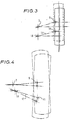
- the geometry of the steering/suspension is altered as shown in Figure 4.
- the pivot points 3, 9, 18 and 15 no longer constitute a parallelogram. This may be achieved in existing vehicles by relocating the pivot bush 3 at the inner end of the suspension arm 1 closer to the inner steering ball joint 18, or by relocating the steering rack closer to the pivot bush 3. In some known vehicles the amount of relocation required may be of the order of 10 mm to 30 mm. Therefore when the wheel moves forwardly or rearwardly as permitted by the compliance device 23, the geometry of the points 3, 9, 18 and 15 is such that the suspension imparts a toe in to the road wheel with forward displacement of the wheel relative to the vehicle and toe out with rearward displacement.
- the geometry of the suspension is such that it causes the wheel to toe in for forward longitudinal displacement of the wheel and to toe out for rearward longitudinal displacement of the wheel by substantially the same amount for a given longitudinal displacement as the toe in and toe out movements which would be caused for the same longitudinal displacement at said critical wobble speed by said out of balance forces in the absence of any restraint of angular movements of the wheel about a substantially vertical axis, whereby the effect of the out of balance forces on the unsprung part of the vehicle is reduced.
- the out of balance forces are such as to cause the suspension arm 1 to move as permitted by the compliance device 23 and pivotal connection 3.
- This movement causes the suspension steering geometry to move the ball joint 15 at the outer end of the steering link 17 to the position the steering link is being moved by the oscillations of the wheel. Consequently, there is no movement of the steering wheel.
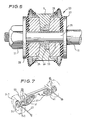
- the novel compliance device which is an important feature of the suspension is shown in Figure 5.
- the end of the stabiliser bar 19 extends through an aperture in the suspension arm 1.
- the end of the bar has a reduced diameter portion 25, with a threaded end portion.
- a retainer 27 engages the shoulder between the large and narrow diameter portions, and the component parts are held between the retainer 27 and the retainer 29 by a nut 31.
- a metal sleeve 33 is mounted on the part 25.
- a bearing 46 fits an aperture in the arm 1 and transfers the loads from the arm 1 to the stabiliser bar 19.
- Located either side of the bearing 46 are two bushes 35 made of micro-cellular polyurethane. These bushes provide the resilience in the compliance device to permit the arm 1 to move relative to the end of the stabiliser bar 19 in the longitudinal direction of the vehicle. As a longitudinal force is exerted on the arm 1 by a wheel in the state of "shimmy", it moves relative to the bar 19 against the bushes 35.
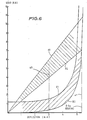
- the y axis represents the load in kilo- newtons on a wheel in the longitudinal direction of the vehicle, which the x axis represents deflection of the compliance device in mm.
- Lines A1 and A2 represent the upper and lower limits for a typical load/deflection characteristic of a conventional compliance device; while curves B1 and B2 represent the upper and lower limits for the deflection characteristic for a car of the size of a Ford Cortina of the novel compliance device according to this invention when the wheels are not oscillating due to shimmy.
- the conventional compliance device has a linear load/deflection characteristic.
- the compliance device of the invention offers little resistance to the initial 3 mm of deflection in either direction. This is achieved by avoiding friction in the device and having very little preload on the bushes 35.
- the compliance device resiliently opposed deflection greater than 3 mm to control braking loads and road shocks.
- Line 47 in Figure 6 corresponds to the deflection produced by 0.8 g braking.
- Line 49 indicates the deflection which occurs at a critical wobble speed due to wheel oscillations.
- the resistance of the compliance device to such deflections must be less than the frictional resistance in the steering linkage to steering movements.
- the deflection characteristic of the compliance device 23 is not the same for all frequencies of oscillation.
- a characteristic of micro-cellular polyurethane is that the elasticity varies inversely with the frequency of the change of load (such as occurs in a shimmy condition).
- the resistance of the compliance device to deflection is greater at higher frequency and hence the free movement allowed by the compliance device is less at a high critical wobble speed than at a low critical wobble speed.
- the elasticity is less than when the lower frequency high amplitude oscillations occur.
- Figure 7 shows an independent rear suspension incorporating the invention. It comprises a suspension arm 37 in the form of a wishbone, a stub axle 39 pivotally connected to the arm 37 for movement about a longitudinal axis of the vehicle, a coil spring 41 and a tie bar 43.
- the suspension arm 37 is pivotally connected to the sprung part of the vehicle about a generally longitudinal axis.
- the pivotal connection of the arm 37 to the vehicle is such that the outer end of the arm can move forwardly or rearwardly through a small distance.
- the camber of the wheel is controlled by a Macpherson strut 45 connected to the stub axle 39 and the body.
- the tie bar 43 is pivotally connected to the sprung part of the vehicle for movement about a transverse axis, and is connected to the suspension arm 37 by a compliance device 145 which is similar to that described above with reference to Figures 5 and 6.
- a compliance device 145 which is similar to that described above with reference to Figures 5 and 6.
Landscapes
- Engineering & Computer Science (AREA)
- Mechanical Engineering (AREA)
- Vehicle Body Suspensions (AREA)
Priority Applications (1)
| Application Number | Priority Date | Filing Date | Title |
|---|---|---|---|
| AT81903107T ATE16261T1 (de) | 1980-11-19 | 1981-11-19 | Aufhaengung fuer kraftfahrzeugraeder. |
Applications Claiming Priority (4)
| Application Number | Priority Date | Filing Date | Title |
|---|---|---|---|
| GB8037015 | 1980-11-19 | ||
| GB8037015 | 1980-11-19 | ||
| GB8113724 | 1981-05-05 | ||
| GB8113724 | 1981-05-05 |
Publications (2)
| Publication Number | Publication Date |
|---|---|
| EP0064996A1 EP0064996A1 (en) | 1982-11-24 |
| EP0064996B1 true EP0064996B1 (en) | 1985-10-30 |
Family
ID=26277561
Family Applications (1)
| Application Number | Title | Priority Date | Filing Date |
|---|---|---|---|
| EP81903107A Expired EP0064996B1 (en) | 1980-11-19 | 1981-11-19 | Motor vehicle wheel suspension |
Country Status (6)
Families Citing this family (28)
| Publication number | Priority date | Publication date | Assignee | Title |
|---|---|---|---|---|
| DE3912399C1 (GUID-C5D7CC26-194C-43D0-91A1-9AE8C70A9BFF.html) * | 1989-04-15 | 1990-08-02 | Daimler-Benz Aktiengesellschaft, 7000 Stuttgart, De | |
| DE4017210C1 (GUID-C5D7CC26-194C-43D0-91A1-9AE8C70A9BFF.html) * | 1990-05-29 | 1991-10-31 | Mercedes-Benz Aktiengesellschaft, 7000 Stuttgart, De | |
| US5538229A (en) * | 1992-10-07 | 1996-07-23 | Ford Motor Company | Anti-rotation apparatus for a vehicle suspension member |
| US5498019A (en) * | 1994-12-15 | 1996-03-12 | Adato; Henri | Suspension system for controlling lateral displacement of a wheel |
| JP3876039B2 (ja) * | 1997-03-21 | 2007-01-31 | 本田技研工業株式会社 | 自動車の操舵装置 |
| US5950751A (en) * | 1997-07-29 | 1999-09-14 | Solorider Industries, Inc. | Electrically-powered vehicle with swivel seat |
| GR1003406B (el) * | 1998-07-06 | 2000-07-25 | Διαιρουμενη αντιστρεπτικη ραβδος | |
| EP1080953A1 (de) * | 1999-09-03 | 2001-03-07 | Ford Global Technologies, Inc., A subsidiary of Ford Motor Company | Radaufhängung für Kraftfahrzeuge mit einer radführenden Blattfeder |
| DE60132643T2 (de) * | 2000-03-28 | 2009-01-08 | Interdigital Technology Corp., Wilmington | CDMA system, welches vor dem Senden eine Vordrehung benutzt |
| AT5080U1 (de) * | 2001-03-23 | 2002-03-25 | Steyr Daimler Puch Ag | Hinterachsaufhängung für kraftfahrzeuge mittels längs- und querlenkern |
| US6561305B2 (en) | 2001-05-08 | 2003-05-13 | Delphi Technologies, Inc. | Hydraulic clutching steering damper |
| US6578854B2 (en) | 2001-07-30 | 2003-06-17 | Solorider Industries, Inc. | Personal mobility vehicle incorporating tilting and swiveling seat and method for use while playing golf |
| KR100412683B1 (ko) * | 2001-08-21 | 2003-12-31 | 현대자동차주식회사 | 리어 서스펜션 시스템 |
| US6834873B1 (en) * | 2002-02-21 | 2004-12-28 | Link Mfg., Ltd. | Axle suspension system |
| US6752425B2 (en) * | 2002-10-30 | 2004-06-22 | Ford Global Technologies, Llc | Semi-active control of automotive steering system vibration with magneto-rheological damping |
| US7234713B1 (en) | 2003-02-21 | 2007-06-26 | Link Mfg. Ltd. | Axle suspension system |
| EP1785335B1 (de) | 2005-11-10 | 2011-01-12 | Ford Global Technologies, LLC | Gelenkverbindung zum Übertragen einer Lenkbewegung auf ein Rad eines Fahrzeuges |
| GB2468302B (en) * | 2009-03-03 | 2013-04-03 | Gordon Murray Design Ltd | Vehicle suspension |
| DE102011083227A1 (de) * | 2011-09-22 | 2013-03-28 | Zf Friedrichshafen Ag | Blattfeder |
| US9469173B2 (en) * | 2011-11-14 | 2016-10-18 | Gordon Murray Design Limited | Vehicle suspension |
| US9302706B2 (en) | 2013-04-15 | 2016-04-05 | Ford Global Technologies, Llc | Articulated connection for transferring a steering movement onto a vehicle wheel |
| DE202013101637U1 (de) | 2013-04-16 | 2013-04-25 | Ford Global Technologies, Llc. | Gelenkverbindung zur Übertragung einer Lenkbewegung auf ein Rad eines Fahrzeuges |
| DE102013206834B4 (de) | 2013-04-16 | 2025-03-13 | Ford Global Technologies, Llc | Gelenkverbindung zur Übertragung einer Lenkbewegung auf ein Rad eines Fahrzeuges |
| DE102014205990B4 (de) | 2013-04-16 | 2023-10-26 | Ford Global Technologies, Llc | Gelenkverbindung zur Übertragung einer Lenkbewegung auf ein Rad eines Fahrzeuges sowie Lenkhebel |
| DE102014213111B4 (de) * | 2013-07-15 | 2020-06-18 | Ford Global Technologies, Llc | Vorrichtung zum Stabilisieren eines Kraftfahrzeugs gegen Wankbewegungen |
| FR3013669B1 (fr) * | 2013-11-28 | 2017-07-14 | Renault Sas | Bloc avant pour un vehicule automobile |
| US10967927B2 (en) | 2017-09-22 | 2021-04-06 | Link Mfg., Ltd. | Mounting brackets for auxiliary suspension systems |
| US11820188B2 (en) | 2021-07-08 | 2023-11-21 | Link Mfg., Ltd. | Driven lift axles and associated systems and methods |
Family Cites Families (10)
| Publication number | Priority date | Publication date | Assignee | Title |
|---|---|---|---|---|
| US3195878A (en) * | 1961-09-13 | 1965-07-20 | Ford Motor Co | Automotive suspension system having a dual stage spring means |
| US3178202A (en) * | 1961-12-04 | 1965-04-13 | Ford Motor Co | Vehicle wheel suspension |
| DE1190809B (de) * | 1962-10-24 | 1965-04-08 | Daimler Benz Ag | Einzelradaufhaengung fuer Fahrzeugraeder, insbesondere fuer die lenkbaren Vorderraeder eines Kraftfahrzeuges mit Frontantrieb |
| GB987670A (en) * | 1964-03-16 | 1965-03-31 | Ford Motor Co | Motor vehicle independent suspension |
| BE717484A (GUID-C5D7CC26-194C-43D0-91A1-9AE8C70A9BFF.html) * | 1967-07-25 | 1968-12-16 | ||
| DE2249913A1 (de) * | 1972-10-12 | 1974-04-18 | Porsche Ag | Radaufhaengung fuer kraftfahrzeuge |
| DE2333950C3 (de) * | 1973-07-04 | 1978-04-13 | Volkswagenwerk Ag, 3180 Wolfsburg | Gelenkte Federbeinachse |
| SE7412950L (sv) * | 1974-10-15 | 1976-04-20 | Volvo Ab | Anordning for dempning av vibrationer i ratten hos ett motorfordon |
| JPS5830725Y2 (ja) * | 1977-12-28 | 1983-07-07 | 本田技研工業株式会社 | 車輌の後輪懸架装置 |
| JPS5538055U (GUID-C5D7CC26-194C-43D0-91A1-9AE8C70A9BFF.html) * | 1978-09-04 | 1980-03-11 |
-
1981
- 1981-11-19 JP JP56503592A patent/JPS57501917A/ja active Pending
- 1981-11-19 WO PCT/GB1981/000249 patent/WO1982001688A1/en not_active Application Discontinuation
- 1981-11-19 BR BR8108870A patent/BR8108870A/pt unknown
- 1981-11-19 EP EP81903107A patent/EP0064996B1/en not_active Expired
- 1981-11-19 US US06/403,736 patent/US4458915A/en not_active Expired - Fee Related
- 1981-11-19 AU AU78039/81A patent/AU552423B2/en not_active Ceased
Also Published As
| Publication number | Publication date |
|---|---|
| WO1982001688A1 (en) | 1982-05-27 |
| EP0064996A1 (en) | 1982-11-24 |
| AU7803981A (en) | 1982-06-07 |
| US4458915A (en) | 1984-07-10 |
| JPS57501917A (GUID-C5D7CC26-194C-43D0-91A1-9AE8C70A9BFF.html) | 1982-10-28 |
| AU552423B2 (en) | 1986-05-29 |
| BR8108870A (pt) | 1982-10-13 |
Similar Documents
| Publication | Publication Date | Title |
|---|---|---|
| EP0064996B1 (en) | Motor vehicle wheel suspension | |
| US4714270A (en) | Independent wheel suspension with toe correcting link | |
| US7427072B2 (en) | Active vehicle suspension | |
| US4834416A (en) | Vehicle rear suspension | |
| US4245853A (en) | Independent wheel suspension for motor vehicles | |
| US5415427A (en) | Wheel suspension system | |
| US5697633A (en) | Suspension system of front wheels for a vehicle | |
| US4456282A (en) | Independent rear wheel suspension with a toe angle controlling trailing arm | |
| US4269432A (en) | Independent wheel suspension for motor vehicles | |
| US4457537A (en) | Independent wheel suspension | |
| US20080203693A1 (en) | In-Wheel Suspension | |
| US4556235A (en) | Independent wheel suspension for non-steered wheels of motor vehicles | |
| KR20050085860A (ko) | 3개의 피봇 서스펜션 시스템을 갖는 차륜 지지장치 및 이지지장치를 구비한 차량 | |
| US4434998A (en) | Rear axle for vehicles especially motor vehicles | |
| US4480852A (en) | Independent rear wheel suspension having a pivotable connection between two transverse control arms | |
| US7270340B2 (en) | Strut with an elastic wheel carrier mount | |
| CN117681605A (zh) | 具有针对后倾控制进行平衡的颠簸缓冲器的悬架 | |
| US7784807B2 (en) | Wheel suspension for motor vehicles | |
| US5411285A (en) | Rear suspension for vehicle | |
| KR20200072989A (ko) | 차량용 현가장치 | |
| EP0323414B1 (en) | Rear suspension for motor vehicles, of the type with independent wheels and longitudinal arms | |
| US4457536A (en) | Independent rear wheel suspension with adjustable toe angle control during recession | |
| JPH111110A (ja) | フロントサスペンション装置 | |
| KR100326663B1 (ko) | 멀티 캠버 모드 서스펜션 | |
| JPS61263809A (ja) | リヤサスペンシヨン |
Legal Events
| Date | Code | Title | Description |
|---|---|---|---|
| PUAI | Public reference made under article 153(3) epc to a published international application that has entered the european phase |
Free format text: ORIGINAL CODE: 0009012 |
|
| 17P | Request for examination filed |
Effective date: 19820716 |
|
| AK | Designated contracting states |
Designated state(s): AT CH DE FR GB NL SE |
|
| GRAA | (expected) grant |
Free format text: ORIGINAL CODE: 0009210 |
|
| AK | Designated contracting states |
Designated state(s): AT CH DE FR GB LI NL SE |
|
| REF | Corresponds to: |
Ref document number: 16261 Country of ref document: AT Date of ref document: 19851115 Kind code of ref document: T |
|
| REF | Corresponds to: |
Ref document number: 3172783 Country of ref document: DE Date of ref document: 19851205 |
|
| ET | Fr: translation filed | ||
| PLBI | Opposition filed |
Free format text: ORIGINAL CODE: 0009260 |
|
| 26 | Opposition filed |
Opponent name: BAYERISCHE MOTOREN WERKE AKTIENGESELLSCHAFT Effective date: 19860724 |
|
| NLR1 | Nl: opposition has been filed with the epo |
Opponent name: BAYERISCHE MOTOREN WERKE AKTIENGESELLSCHAFT |
|
| PGFP | Annual fee paid to national office [announced via postgrant information from national office to epo] |
Ref country code: AT Payment date: 19861112 Year of fee payment: 6 |
|
| PGFP | Annual fee paid to national office [announced via postgrant information from national office to epo] |
Ref country code: NL Payment date: 19861130 Year of fee payment: 6 |
|
| REG | Reference to a national code |
Ref country code: GB Ref legal event code: 746 |
|
| REG | Reference to a national code |
Ref country code: FR Ref legal event code: DL |
|
| RDAG | Patent revoked |
Free format text: ORIGINAL CODE: 0009271 |
|
| STAA | Information on the status of an ep patent application or granted ep patent |
Free format text: STATUS: PATENT REVOKED |
|
| 27W | Patent revoked |
Effective date: 19870314 |
|
| NLR2 | Nl: decision of opposition | ||
| REG | Reference to a national code |
Ref country code: CH Ref legal event code: PL |
|
| GBPR | Gb: patent revoked under art. 102 of the ep convention designating the uk as contracting state | ||
| EUG | Se: european patent has lapsed |
Ref document number: 81903107.1 Effective date: 19880913 |