EP0064656A1 - Pile électrochimique stockable - Google Patents
Pile électrochimique stockable Download PDFInfo
- Publication number
- EP0064656A1 EP0064656A1 EP82103506A EP82103506A EP0064656A1 EP 0064656 A1 EP0064656 A1 EP 0064656A1 EP 82103506 A EP82103506 A EP 82103506A EP 82103506 A EP82103506 A EP 82103506A EP 0064656 A1 EP0064656 A1 EP 0064656A1
- Authority
- EP
- European Patent Office
- Prior art keywords
- storage cell
- closure
- electrochemical storage
- closure element
- cell according
- Prior art date
- Legal status (The legal status is an assumption and is not a legal conclusion. Google has not performed a legal analysis and makes no representation as to the accuracy of the status listed.)
- Granted
Links
Images

Classifications
-
- H—ELECTRICITY
- H01—ELECTRIC ELEMENTS
- H01M—PROCESSES OR MEANS, e.g. BATTERIES, FOR THE DIRECT CONVERSION OF CHEMICAL ENERGY INTO ELECTRICAL ENERGY
- H01M10/00—Secondary cells; Manufacture thereof
- H01M10/36—Accumulators not provided for in groups H01M10/05-H01M10/34
- H01M10/39—Accumulators not provided for in groups H01M10/05-H01M10/34 working at high temperature
- H01M10/3909—Sodium-sulfur cells
-
- Y—GENERAL TAGGING OF NEW TECHNOLOGICAL DEVELOPMENTS; GENERAL TAGGING OF CROSS-SECTIONAL TECHNOLOGIES SPANNING OVER SEVERAL SECTIONS OF THE IPC; TECHNICAL SUBJECTS COVERED BY FORMER USPC CROSS-REFERENCE ART COLLECTIONS [XRACs] AND DIGESTS
- Y02—TECHNOLOGIES OR APPLICATIONS FOR MITIGATION OR ADAPTATION AGAINST CLIMATE CHANGE
- Y02E—REDUCTION OF GREENHOUSE GAS [GHG] EMISSIONS, RELATED TO ENERGY GENERATION, TRANSMISSION OR DISTRIBUTION
- Y02E60/00—Enabling technologies; Technologies with a potential or indirect contribution to GHG emissions mitigation
- Y02E60/10—Energy storage using batteries
Definitions
- the invention relates to an electrochemical storage cell based on alkali metal and chalcogen with at least one anode compartment intended for receiving the anolyte and one cathode compartment intended for receiving the catholyte, which is separated from one another by an alkali ion-conducting solid electrolyte and at least partially delimited by a metallic housing are, the solid electrolyte is cup-shaped and is non-positively connected at its open end to at least one annular insulating body, and protrudes into its inner region a rod-shaped current collector which penetrates the closure of the storage cell and protrudes outwards.
- Such rechargeable electrochemical storage cells with solid electrolytes are very suitable for building up accumulators with a high energy and power density.
- the solid electrolytes used in the alkali / chalcogen storage cells which are made, for example, of beta-aluminum oxide, are distinguished by the fact that the partial conductivity of the mobile ion is very high and the partial conductivity of the electrons by many Zener powers is smaller.
- the use of such solid electrolytes for the construction of electrochemical memory cells means that practically no self-discharge takes place, since the electron conductivity is negligible and the reaction substances cannot pass through the solid electrolyte as neutral particles.
- a special example of such rechargeable electrochemical storage cells are those based on sodium and sulfur, the solid electrolyte of which is made from beta aluminum oxide.
- An advantage of these electrochemical memory cells is that no side reactions occur when the memory cells are loaded. The reason for this is again that only one type of ion can get through the solid electrolyte. The current yield of such a sodium / sulfur storage cell is therefore around 100%.
- the ratio of the energy content to the total weight of such a storage cell is very high in comparison to the lead accumulator, since the reactants are light and a lot of energy is released in the electrochemical reaction.
- Electrochemical storage cells based on sodium and sulfur therefore have considerable advantages over conventional accumulators, such as lead accumulators.
- Patent application P 30 33 438.4 describes an electrochemical storage cell in which the thermal compression method has been used to form the cell closure.
- the disadvantage here is that for the formation of this closure, the ring space which lies between the metallic housing and the solid electrolyte must be made wider than normal, since the closure part lying outside the solid electrolyte is itself very wide.
- the invention is therefore based on the object of providing an electrochemical storage cell in which a widening of the annular space between the metal housing and the solid electrolyte is avoided for the formation of the cell closure using the thermal compression process.
- the closure comprises at least two closure elements which are at least partially plate-shaped and at least one first closure element is fastened to the housing and a second closure element is fastened to the rod-shaped current collector, and in that all the closure elements additionally connected to the insulating ring of the solid electrolyte on the same side and insulated from one another.
- each closure element is placed on the upper side of the insulating ring made of alpha aluminum oxide with the interposition of at least one aluminum ring washer and non-positively connected thereto by using the thermal compression method.
- the two closure elements are made of stainless steel.
- the first closure element is designed as a cylinder which is provided on one side with an inwardly facing flange. The width of this flange is selected so that it covers at least the space between the solid electrolyte and the housing.
- the flange of the first closure element is placed over the aluminum ring washer on the insulating ring of the solid electrolyte and non-positively connected to it.
- the outer surface of the cylinder is non-positively connected to the inner surface of the metallic housing.
- the second closure element is designed as an annular disk.
- the diameter of the ring disk is chosen so large that at least the interior of the solid electrolyte is covered by the second closure element.
- the outer edge of the ring disk is placed on the second aluminum ring disk resting on the insulating ring and is non-positively connected to the insulating ring.
- the arrangement of aluminum washers between each of the two closure elements and the insulating ring enables a force-fit connection of the elements with the aid of the already known thermocompression method. This creates a closure that is permanently stable, in particular at the temperatures prevailing in the storage cell and the reactants that form.
- the two closure elements, each connected to the insulating ring of the solid electrolyte via an aluminum washer, are preferably made of stainless steel. Since, as already mentioned above, the first closure element is connected to the housing and the second closure element is connected to the rod-shaped current collector, the two closure elements must be insulated from one another. This is done through a lip that is crimped on the top of the insulating ring.
- the lip is arranged approximately in the middle of the insulating ring and guided all around.
- the outer loading boundary edges of the closure elements are brought up to this lip from both sides.
- the lip is also made of alpha aluminum oxide, so that no electrically conductive connection is possible between the two closure elements.
- the insulating ring is provided with a recess on its outward-facing side.
- the bond tool necessary for carrying out the thermal compression process can be supported in this recess.
- both closure elements are made of aluminum.
- the second closure element is placed directly on the insulating ring of the solid electrolyte and non-positively connected to it with the aid of the thermal compression process.
- the first closure element is placed on the second closure element with the interposition of an alpha-aluminum washer and also non-positively connected to it by using the thermal compression method.
- a memory cell with such a closure can be produced with a smaller diameter and can be closed with the aid of the thermal compression process than is possible with conventional memory cells. This is particularly important in the case of inverse memory cells in which the sulfur is arranged within the solid electrolyte and the sodium is arranged within the annular space, since the diameter of the metal housing can be made considerably smaller when using the memory cell according to the invention because of the lower cell capacity.
- the smaller diameter of the memory cells also makes it possible to insert a larger number of memory cells to accommodate a battery, or the battery can be made smaller with the same number of memory cells.
- a further advantage results in the memory cell according to the invention for connecting the insulating ring to the solid electrolyte. Since the insulating ring is made of alpha aluminum oxide, it is preferably attached to the solid electrolyte by a glass solder. Since in the embodiments of the memory cell according to the invention described here, the closure elements are all connected to the top of the insulating ring, the underside of the insulating ring does not need to be cleaned as carefully as before from the glass solder, since no further components of the memory cell are attached there .
- Another advantage of the memory cell according to the invention results for large-scale production.
- the metal parts only have to be fed from one side. The same applies to the application of the compressive force that is required when connecting the components using the thermal compression process.
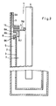
- the electrochemical storage cell 1 shown in FIG. 1 is essentially formed from a cup-shaped housing 2, a solid electrolyte 3, a current collector 4 and a closure 5.
- the cup-shaped housing 2 is made of metal and is designed as a tube closed on one side. Internally the solid electrolyte, which is also cup-shaped, is arranged in this housing.
- the embodiment of the solid electrolyte 3 shown here is made of beta aluminum oxide. The dimensions of the solid electrolyte 3 are chosen so that a continuous space 6 is formed between its outer surfaces and the inner surfaces of the metallic housing 2, which serves as one of the reactant spaces.
- the interior 7 of the solid electrolyte 3 forms the second reactant space in the exemplary embodiment described here.
- the height of the solid electrolyte 3 is selected to be slightly smaller than the height of the housing 2.
- the solid electrolyte is provided with an insulating ring 8 at its open end. This is made of alpha aluminum oxide and attached to the solid electrolyte 3 by means of a glass solder (not shown here).
- the insulating ring 8 is placed on the solid electrolyte 3 in such a way that it forms an inward and outward-facing flange 8 A or 8 I.
- the insulating ring 8 is additionally provided with an edge 8K pointing downwards. With their help, an exact centering of the insulating ring 8 on the solid electrolyte 3 is possible.
- the desired position of the insulating ring 8 on the solid electrolyte 3 is only reached when the edge 8 K lies exactly on the outer surface of the solid electrolyte 3.
- the insulating ring 8 is provided with a recess 8 N on its outward-facing side surface. This is necessary for the formation of the cell closure with the thermal compression process.
- the bond tool necessary for carrying out the thermal compression process can be supported in the recess 8N.
- the insulating ring 8 On its upward-facing side, the insulating ring 8 is provided in the center with a lip 8 L which is guided all round.
- An aluminum ring 9 A or 9 B is placed on the insulating ring 8 on both sides of the lip.
- the closure 5 of the memory cell is formed by two closure elements 5 A and 5 B.
- the first closure element 5 A has partially the shape of a cylinder, which point inwards has the flange 10. This forms the plate-shaped part of the closure element 5 A.
- the outer diameter of the cylinder is adapted to the inner diameter of the housing 2.
- the width of the flange 10 is selected so that the space 6 formed between the housing 2 and the solid electrolyte 3 is at least covered.
- the flange 10 is chosen so wide that it extends to the lip 8 L of the insulating ring 8.
- the height of the closure element 5 A, in particular of the cylinder depends on the distance between the upper end of the housing 2 and the surface of the insulating ring 8.
- the outer surfaces of the cylinder 5 A are non-positively connected to the inner surfaces of the housing 2.
- the cylinder 5 A is welded to the inner surfaces of the housing 2.
- the flange 10 is placed on the aluminum ring 9 A and non-positively connected to the insulating ring 8 by the thermal compression method.
- the closure 5 of the memory cell 1 has a second closure element 5 B. This is formed by an washer. The diameter of this ring disk is chosen so large that the interior 7 of the solid electrolyte 3 is completely covered.
- the diameter of the washer 5 B. is chosen so that its outer edge extends to the lip 8 L of the insulating ring 8. With its downward-facing edge, the washer 5 B is placed on the aluminum ring 9 B and is non-positively connected to the insulating ring 8 using the thermal compression method.
- the annular disc 5 B is penetrated centrally by the current collector 4, which protrudes into the solid electrolyte 3 and protrudes outwards via the closure 5.
- the annular disc 5 B is non-positively connected to the pantograph 4. In order to form an optimal cell seal, the edge of the ring disk, which is adjacent to the current collector 4, is pulled slightly upwards.
- the two closure elements 5 A and 5 B must in the event that the housing 2 as a pantograph serves to be electrically isolated from each other. This is done by the lip 8 L, which is molded onto the insulating ring 8. It also consists of alpha aluminum oxide and separates the two closure elements 5 A and 5 B, which are brought up to them from both sides.
- the housing 2 and the closure 5 are made of stainless steel.
- the current collector 4 is a rod made of metal.
- the interior 7 of the solid electrolyte 3 serves as a cathode space and is filled with sulfur.
- the space 6 between the housing 2 and the solid electrolyte 3 is filled with sodium and serves as an anode space.
- the metal housing 2 acts as the anodic current collector. It is of course possible to interchange the function of the two reactant spaces 6 and 7.
- FIG. 2 shows a variant of the memory cell 1 shown in FIG. 1 and explained in the associated description.
- the memory cell 1 shown here again comprises a housing 2 made of metal, a solid electrolyte 3, a current collector 4 and a closure 5.
- the solid electrolyte 3 is also provided with an insulating ring 8. This is essentially designed like the insulating ring 8 according to FIG. 1. In this case, only an insulating lip 8 L was formed.
- the closure 5 of the memory cell 1 is also formed here by two closure elements 5 A and 5 B.
- the closure element 5 A is in this case again in some areas designed as a cylinder which has an inwardly facing flange 10.
- the closure element 5 B has the shape of an annular disc.
- the diameter of the ring washer is chosen so large that its outer edge lies in one plane with the outer edge of the insulating ring. 5.
- Both closure elements 5 A and 5 B are made of aluminum.
- the closure element 5 B is arranged directly on the surface of the insulating ring 8 and is non-positively connected to it by the thermal compression method.
- the annular disc 5 B is penetrated in the middle by the current collector 4, which projects into the interior of the solid electrolyte 3 and protrudes outwards a few mm beyond the closure 5. To form a secure seal, the edge of the annular disc 5 B adjoining the current collector 4 is pulled up slightly and welded to the current collector 4.
- an annular disc 15 made of alpha aluminum oxide is placed in the area of the insulating ring 8.
- the width of the annular disc 15 corresponds approximately to the width of the insulating ring 8.
- the flange 10 of the first closure element 5A is placed on this annular disc 15.
- the width of the flange 10 is chosen so that its outer boundary is flush with the inner boundary of the insulating ring 8.
- the first closure element 5 A is also non-positively connected to the insulating ring 8 through the use of the thermal compression method.
- the connecting element 5 A is partially designed as a cylinder. The height of the cylinder is dimensioned so that the connecting element 5 A closes in one plane with the housing 2.
- the outer surface of the cylinder is non-positively connected to the inner surface of the housing 2.
- the housing 2 can also be made of aluminum.
- the interior 7 of the solid electrolyte 3 serves as the cathode space.
- the space 6 between the housing 2 and the solid electrolyte 3 forms the anode space.
- the function of the two reactant spaces 6 and 7 can also be interchanged without problems in this memory cell.
Applications Claiming Priority (2)
| Application Number | Priority Date | Filing Date | Title |
|---|---|---|---|
| DE3117383 | 1981-05-02 | ||
| DE19813117383 DE3117383A1 (de) | 1981-05-02 | 1981-05-02 | "elektrochemische speicherzelle" |
Publications (2)
| Publication Number | Publication Date |
|---|---|
| EP0064656A1 true EP0064656A1 (fr) | 1982-11-17 |
| EP0064656B1 EP0064656B1 (fr) | 1985-09-18 |
Family
ID=6131286
Family Applications (1)
| Application Number | Title | Priority Date | Filing Date |
|---|---|---|---|
| EP82103506A Expired EP0064656B1 (fr) | 1981-05-02 | 1982-04-26 | Pile électrochimique stockable |
Country Status (4)
| Country | Link |
|---|---|
| US (1) | US4473624A (fr) |
| EP (1) | EP0064656B1 (fr) |
| JP (1) | JPS57187875A (fr) |
| DE (1) | DE3117383A1 (fr) |
Cited By (5)
| Publication number | Priority date | Publication date | Assignee | Title |
|---|---|---|---|---|
| EP0142030A2 (fr) * | 1983-11-09 | 1985-05-22 | Asea Brown Boveri Aktiengesellschaft | Elément de stockage d'énergie électrochimique |
| EP0158815A1 (fr) * | 1984-04-02 | 1985-10-23 | BROWN, BOVERI & CIE Aktiengesellschaft | Elément d'accumulateur électrochimique |
| EP0166605A2 (fr) * | 1984-06-26 | 1986-01-02 | Chloride Silent Power Limited | Piles sodium soufre et leur fabrication |
| WO1989004068A1 (fr) * | 1987-10-23 | 1989-05-05 | Chloride Silent Power Limited | Dispositif de conversion d'energie de metal alcalin et procede de construction |
| WO1989004069A1 (fr) * | 1987-10-23 | 1989-05-05 | Chloride Silent Power Limited | Procede et appareil de construction d'un dispositif de conversion d'energie de metal alcalin |
Families Citing this family (2)
| Publication number | Priority date | Publication date | Assignee | Title |
|---|---|---|---|---|
| DE4336236C1 (de) * | 1993-10-23 | 1995-01-05 | Abb Patent Gmbh | Elektrochemische Speicherzelle |
| GB9604133D0 (en) * | 1996-02-27 | 1996-05-01 | Programme 3 Patent Holdings | Electrochemical cell |
Citations (6)
| Publication number | Priority date | Publication date | Assignee | Title |
|---|---|---|---|---|
| FR2315778A1 (fr) * | 1975-07-02 | 1977-01-21 | United Kingdom Government | Cellules electriques a anode et cathode liquides |
| FR2327647A1 (fr) * | 1975-10-10 | 1977-05-06 | Chloride Silent Power Ltd | Elements de batteries du type metal alcalin/soufre et leur procede de fabrication |
| GB1502693A (en) * | 1976-02-09 | 1978-03-01 | Chloride Silent Power Ltd | Sealing of electro-chemical devices utilising liquid sodium and a solid ceramic electrolyte permeable to sodium ion |
| US4105834A (en) * | 1976-10-14 | 1978-08-08 | Baker Derrick John | Electric cells |
| US4197363A (en) * | 1978-10-26 | 1980-04-08 | Ford Motor Company | Seal for sodium sulfur battery |
| EP0018190A1 (fr) * | 1979-04-19 | 1980-10-29 | Chloride Silent Power Limited | Joints d'étanchéité en verre pour sceller le bêta-alumine dans des cellules électrochimiques ou autres dispositifs de conversion d'énergie, verres utilisables pour ces joints et cellules ou autres dispositifs de conversion d'énergie comportant de tels scellements |
Family Cites Families (10)
| Publication number | Priority date | Publication date | Assignee | Title |
|---|---|---|---|---|
| US2544115A (en) * | 1945-12-22 | 1951-03-06 | Glenside Bag Company | Leakproof battery |
| US3939007A (en) * | 1973-01-16 | 1976-02-17 | British Railways Board | Sodium sulphur cells |
| US4129690A (en) * | 1974-02-15 | 1978-12-12 | The Electricity Council | Sodium sulphur cells |
| US4124739A (en) * | 1974-11-28 | 1978-11-07 | Chloride Silent Power Ltd. | Alkali metal-sulphur cells |
| FR2333358A1 (fr) * | 1975-11-28 | 1977-06-24 | Comp Generale Electricite | Generateur electrochimique du type soufre-sodium |
| US4052533A (en) * | 1976-03-29 | 1977-10-04 | Union Carbide Corporation | Pressure relief flapper vent valve for galvanic cells |
| JPS5446626A (en) * | 1977-09-21 | 1979-04-12 | Nippon Gakki Seizo Kk | Racket |
| US4234668A (en) * | 1978-04-20 | 1980-11-18 | General Electric Company | Composite sulfur electrode container and method of manufacture |
| US4192911A (en) * | 1978-11-01 | 1980-03-11 | Ford Motor Company | Sodium sulfur battery seal |
| DE3114348A1 (de) * | 1981-04-09 | 1982-11-04 | Brown, Boveri & Cie Ag, 6800 Mannheim | "wiederaufladbare galvanische einzelzelle" |
-
1981
- 1981-05-02 DE DE19813117383 patent/DE3117383A1/de active Granted
-
1982
- 1982-04-23 US US06/371,124 patent/US4473624A/en not_active Expired - Fee Related
- 1982-04-26 EP EP82103506A patent/EP0064656B1/fr not_active Expired
- 1982-04-30 JP JP57073273A patent/JPS57187875A/ja active Pending
Patent Citations (6)
| Publication number | Priority date | Publication date | Assignee | Title |
|---|---|---|---|---|
| FR2315778A1 (fr) * | 1975-07-02 | 1977-01-21 | United Kingdom Government | Cellules electriques a anode et cathode liquides |
| FR2327647A1 (fr) * | 1975-10-10 | 1977-05-06 | Chloride Silent Power Ltd | Elements de batteries du type metal alcalin/soufre et leur procede de fabrication |
| GB1502693A (en) * | 1976-02-09 | 1978-03-01 | Chloride Silent Power Ltd | Sealing of electro-chemical devices utilising liquid sodium and a solid ceramic electrolyte permeable to sodium ion |
| US4105834A (en) * | 1976-10-14 | 1978-08-08 | Baker Derrick John | Electric cells |
| US4197363A (en) * | 1978-10-26 | 1980-04-08 | Ford Motor Company | Seal for sodium sulfur battery |
| EP0018190A1 (fr) * | 1979-04-19 | 1980-10-29 | Chloride Silent Power Limited | Joints d'étanchéité en verre pour sceller le bêta-alumine dans des cellules électrochimiques ou autres dispositifs de conversion d'énergie, verres utilisables pour ces joints et cellules ou autres dispositifs de conversion d'énergie comportant de tels scellements |
Cited By (15)
| Publication number | Priority date | Publication date | Assignee | Title |
|---|---|---|---|---|
| EP0142030A3 (en) * | 1983-11-09 | 1986-12-03 | Brown, Boveri & Cie Aktiengesellschaft | Electrochemical storage cell |
| EP0142030A2 (fr) * | 1983-11-09 | 1985-05-22 | Asea Brown Boveri Aktiengesellschaft | Elément de stockage d'énergie électrochimique |
| EP0158815A1 (fr) * | 1984-04-02 | 1985-10-23 | BROWN, BOVERI & CIE Aktiengesellschaft | Elément d'accumulateur électrochimique |
| US4759999A (en) * | 1984-06-26 | 1988-07-26 | Chloride Silent Power Limited | Sodium sulphur cells and their manufacture |
| EP0166605A3 (en) * | 1984-06-26 | 1987-03-25 | Chloride Silent Power Limited | Sodium sulphur cells and their manufacture |
| AU573853B2 (en) * | 1984-06-26 | 1988-06-23 | Chloride Silent Power Ltd. | Sodium sulphide cell having lid sealed to case by thermocompression bonding |
| EP0166605A2 (fr) * | 1984-06-26 | 1986-01-02 | Chloride Silent Power Limited | Piles sodium soufre et leur fabrication |
| WO1989004068A1 (fr) * | 1987-10-23 | 1989-05-05 | Chloride Silent Power Limited | Dispositif de conversion d'energie de metal alcalin et procede de construction |
| WO1989004069A1 (fr) * | 1987-10-23 | 1989-05-05 | Chloride Silent Power Limited | Procede et appareil de construction d'un dispositif de conversion d'energie de metal alcalin |
| GB2230378A (en) * | 1987-10-23 | 1990-10-17 | Chloride Silent Power Ltd | Method of and apparatus for constructing an alkali metal energy conversion device |
| GB2231712A (en) * | 1987-10-23 | 1990-11-21 | Chloride Silent Power Ltd | Alkali metal energy conversion device and method of construction |
| GB2230378B (en) * | 1987-10-23 | 1991-03-27 | Chloride Silent Power Ltd | Apparatus for constructing an alkali metal energy conversion device |
| GB2231712B (en) * | 1987-10-23 | 1991-07-17 | Chloride Silent Power Ltd | Alkali metal energy conversion device and method of construction |
| US5075957A (en) * | 1987-10-23 | 1991-12-31 | Chloride Silent Power, Limited | Apparatus for constructing an alkali metal energy conversion device |
| US5118574A (en) * | 1987-10-23 | 1992-06-02 | Chloride Silent Power Limited | Alkali metal energy conversion device and method of construction |
Also Published As
| Publication number | Publication date |
|---|---|
| DE3117383C2 (fr) | 1988-03-31 |
| US4473624A (en) | 1984-09-25 |
| EP0064656B1 (fr) | 1985-09-18 |
| DE3117383A1 (de) | 1982-11-18 |
| JPS57187875A (en) | 1982-11-18 |
Similar Documents
| Publication | Publication Date | Title |
|---|---|---|
| DE3340079C2 (fr) | ||
| DE3033438C2 (de) | Elektrochemische Speicherzelle | |
| DE3420585A1 (de) | Bipolare metall-luftsauerstoffbatterie mit einer sich selbst erhaltenden anode | |
| DE2803211A1 (de) | Elektrochemische zelle und kathode dafuer | |
| EP0064234B1 (fr) | Pile électronique conservable | |
| EP0142030B1 (fr) | Elément de stockage d'énergie électrochimique | |
| EP0064676B1 (fr) | Elément d'accumulateur électrochimique | |
| EP0064656B1 (fr) | Pile électrochimique stockable | |
| EP0064655A1 (fr) | Elément de shuntage | |
| DE3102771C2 (de) | Elektrische Batterie mit Schichtaufbau | |
| EP0079582B1 (fr) | Pile électrochimique rechargeable | |
| EP0158815B1 (fr) | Elément d'accumulateur électrochimique | |
| DE2312819C3 (de) | Galvanisches gas-depolarisiertes Element | |
| DE2652012C2 (de) | Elektrochemischer Generator auf Schwefel-Natriumbasis | |
| DE3631965C2 (de) | Verfahren zur Herstellung einer Anschlußdurchführung für eine Batterie bestehend aus übereinandergestapelten Zellen | |
| DE3039013A1 (de) | Elektrochemischer generator | |
| WO2003094264A2 (fr) | Pile a combustible et procede de production de ladite pile | |
| EP0187305B1 (fr) | Elément de stockage d'énergie électrochimique | |
| DE3150702C2 (de) | Verfahren zur Herstellung einer elektrochemischen Speicherzelle sowie eine nach diesem Verfahren hergestellte Speicherzelle | |
| EP0077538B1 (fr) | Pile électrochimique rechargeable | |
| DE3248110A1 (de) | Elektrochemische speicherzelle | |
| DE3615239A1 (de) | Elektrochemische speicherzelle | |
| DE3108188A1 (de) | Bleiakkumulator | |
| DE3338955A1 (de) | Elektrochemische speicherzelle | |
| DE2803212A1 (de) | Prismatische alkalimetallanode fuer eine elektrochemische zelle |
Legal Events
| Date | Code | Title | Description |
|---|---|---|---|
| PUAI | Public reference made under article 153(3) epc to a published international application that has entered the european phase |
Free format text: ORIGINAL CODE: 0009012 |
|
| AK | Designated contracting states |
Designated state(s): BE FR GB IT NL |
|
| 17P | Request for examination filed |
Effective date: 19830409 |
|
| GRAA | (expected) grant |
Free format text: ORIGINAL CODE: 0009210 |
|
| AK | Designated contracting states |
Designated state(s): BE FR GB IT NL |
|
| ITF | It: translation for a ep patent filed |
Owner name: MODIANO & ASSOCIATI S.R.L. |
|
| ET | Fr: translation filed | ||
| PG25 | Lapsed in a contracting state [announced via postgrant information from national office to epo] |
Ref country code: BE Effective date: 19860430 |
|
| PLBE | No opposition filed within time limit |
Free format text: ORIGINAL CODE: 0009261 |
|
| STAA | Information on the status of an ep patent application or granted ep patent |
Free format text: STATUS: NO OPPOSITION FILED WITHIN TIME LIMIT |
|
| 26N | No opposition filed | ||
| BERE | Be: lapsed |
Owner name: BROWN BOVERI & CIE A.G. Effective date: 19860430 |
|
| PGFP | Annual fee paid to national office [announced via postgrant information from national office to epo] |
Ref country code: GB Payment date: 19900228 Year of fee payment: 9 |
|
| PGFP | Annual fee paid to national office [announced via postgrant information from national office to epo] |
Ref country code: FR Payment date: 19900323 Year of fee payment: 9 |
|
| ITTA | It: last paid annual fee | ||
| PGFP | Annual fee paid to national office [announced via postgrant information from national office to epo] |
Ref country code: NL Payment date: 19900430 Year of fee payment: 9 |
|
| PG25 | Lapsed in a contracting state [announced via postgrant information from national office to epo] |
Ref country code: GB Effective date: 19910426 |
|
| PG25 | Lapsed in a contracting state [announced via postgrant information from national office to epo] |
Ref country code: NL Effective date: 19911101 |
|
| NLV4 | Nl: lapsed or anulled due to non-payment of the annual fee | ||
| PG25 | Lapsed in a contracting state [announced via postgrant information from national office to epo] |
Ref country code: FR Effective date: 19911230 |
|
| GBPC | Gb: european patent ceased through non-payment of renewal fee | ||
| REG | Reference to a national code |
Ref country code: FR Ref legal event code: ST |