EP0064656A1 - Electrochemical storage cell - Google Patents
Electrochemical storage cell Download PDFInfo
- Publication number
- EP0064656A1 EP0064656A1 EP82103506A EP82103506A EP0064656A1 EP 0064656 A1 EP0064656 A1 EP 0064656A1 EP 82103506 A EP82103506 A EP 82103506A EP 82103506 A EP82103506 A EP 82103506A EP 0064656 A1 EP0064656 A1 EP 0064656A1
- Authority
- EP
- European Patent Office
- Prior art keywords
- storage cell
- closure
- electrochemical storage
- closure element
- cell according
- Prior art date
- Legal status (The legal status is an assumption and is not a legal conclusion. Google has not performed a legal analysis and makes no representation as to the accuracy of the status listed.)
- Granted
Links
Images

Classifications
-
- H—ELECTRICITY
- H01—ELECTRIC ELEMENTS
- H01M—PROCESSES OR MEANS, e.g. BATTERIES, FOR THE DIRECT CONVERSION OF CHEMICAL ENERGY INTO ELECTRICAL ENERGY
- H01M10/00—Secondary cells; Manufacture thereof
- H01M10/36—Accumulators not provided for in groups H01M10/05-H01M10/34
- H01M10/39—Accumulators not provided for in groups H01M10/05-H01M10/34 working at high temperature
- H01M10/3909—Sodium-sulfur cells
-
- Y—GENERAL TAGGING OF NEW TECHNOLOGICAL DEVELOPMENTS; GENERAL TAGGING OF CROSS-SECTIONAL TECHNOLOGIES SPANNING OVER SEVERAL SECTIONS OF THE IPC; TECHNICAL SUBJECTS COVERED BY FORMER USPC CROSS-REFERENCE ART COLLECTIONS [XRACs] AND DIGESTS
- Y02—TECHNOLOGIES OR APPLICATIONS FOR MITIGATION OR ADAPTATION AGAINST CLIMATE CHANGE
- Y02E—REDUCTION OF GREENHOUSE GAS [GHG] EMISSIONS, RELATED TO ENERGY GENERATION, TRANSMISSION OR DISTRIBUTION
- Y02E60/00—Enabling technologies; Technologies with a potential or indirect contribution to GHG emissions mitigation
- Y02E60/10—Energy storage using batteries
Definitions
- the invention relates to an electrochemical storage cell based on alkali metal and chalcogen with at least one anode compartment intended for receiving the anolyte and one cathode compartment intended for receiving the catholyte, which is separated from one another by an alkali ion-conducting solid electrolyte and at least partially delimited by a metallic housing are, the solid electrolyte is cup-shaped and is non-positively connected at its open end to at least one annular insulating body, and protrudes into its inner region a rod-shaped current collector which penetrates the closure of the storage cell and protrudes outwards.
- Such rechargeable electrochemical storage cells with solid electrolytes are very suitable for building up accumulators with a high energy and power density.
- the solid electrolytes used in the alkali / chalcogen storage cells which are made, for example, of beta-aluminum oxide, are distinguished by the fact that the partial conductivity of the mobile ion is very high and the partial conductivity of the electrons by many Zener powers is smaller.
- the use of such solid electrolytes for the construction of electrochemical memory cells means that practically no self-discharge takes place, since the electron conductivity is negligible and the reaction substances cannot pass through the solid electrolyte as neutral particles.
- a special example of such rechargeable electrochemical storage cells are those based on sodium and sulfur, the solid electrolyte of which is made from beta aluminum oxide.
- An advantage of these electrochemical memory cells is that no side reactions occur when the memory cells are loaded. The reason for this is again that only one type of ion can get through the solid electrolyte. The current yield of such a sodium / sulfur storage cell is therefore around 100%.
- the ratio of the energy content to the total weight of such a storage cell is very high in comparison to the lead accumulator, since the reactants are light and a lot of energy is released in the electrochemical reaction.
- Electrochemical storage cells based on sodium and sulfur therefore have considerable advantages over conventional accumulators, such as lead accumulators.
- Patent application P 30 33 438.4 describes an electrochemical storage cell in which the thermal compression method has been used to form the cell closure.
- the disadvantage here is that for the formation of this closure, the ring space which lies between the metallic housing and the solid electrolyte must be made wider than normal, since the closure part lying outside the solid electrolyte is itself very wide.
- the invention is therefore based on the object of providing an electrochemical storage cell in which a widening of the annular space between the metal housing and the solid electrolyte is avoided for the formation of the cell closure using the thermal compression process.
- the closure comprises at least two closure elements which are at least partially plate-shaped and at least one first closure element is fastened to the housing and a second closure element is fastened to the rod-shaped current collector, and in that all the closure elements additionally connected to the insulating ring of the solid electrolyte on the same side and insulated from one another.
- each closure element is placed on the upper side of the insulating ring made of alpha aluminum oxide with the interposition of at least one aluminum ring washer and non-positively connected thereto by using the thermal compression method.
- the two closure elements are made of stainless steel.
- the first closure element is designed as a cylinder which is provided on one side with an inwardly facing flange. The width of this flange is selected so that it covers at least the space between the solid electrolyte and the housing.
- the flange of the first closure element is placed over the aluminum ring washer on the insulating ring of the solid electrolyte and non-positively connected to it.
- the outer surface of the cylinder is non-positively connected to the inner surface of the metallic housing.
- the second closure element is designed as an annular disk.
- the diameter of the ring disk is chosen so large that at least the interior of the solid electrolyte is covered by the second closure element.
- the outer edge of the ring disk is placed on the second aluminum ring disk resting on the insulating ring and is non-positively connected to the insulating ring.
- the arrangement of aluminum washers between each of the two closure elements and the insulating ring enables a force-fit connection of the elements with the aid of the already known thermocompression method. This creates a closure that is permanently stable, in particular at the temperatures prevailing in the storage cell and the reactants that form.
- the two closure elements, each connected to the insulating ring of the solid electrolyte via an aluminum washer, are preferably made of stainless steel. Since, as already mentioned above, the first closure element is connected to the housing and the second closure element is connected to the rod-shaped current collector, the two closure elements must be insulated from one another. This is done through a lip that is crimped on the top of the insulating ring.
- the lip is arranged approximately in the middle of the insulating ring and guided all around.
- the outer loading boundary edges of the closure elements are brought up to this lip from both sides.
- the lip is also made of alpha aluminum oxide, so that no electrically conductive connection is possible between the two closure elements.
- the insulating ring is provided with a recess on its outward-facing side.
- the bond tool necessary for carrying out the thermal compression process can be supported in this recess.
- both closure elements are made of aluminum.
- the second closure element is placed directly on the insulating ring of the solid electrolyte and non-positively connected to it with the aid of the thermal compression process.
- the first closure element is placed on the second closure element with the interposition of an alpha-aluminum washer and also non-positively connected to it by using the thermal compression method.
- a memory cell with such a closure can be produced with a smaller diameter and can be closed with the aid of the thermal compression process than is possible with conventional memory cells. This is particularly important in the case of inverse memory cells in which the sulfur is arranged within the solid electrolyte and the sodium is arranged within the annular space, since the diameter of the metal housing can be made considerably smaller when using the memory cell according to the invention because of the lower cell capacity.
- the smaller diameter of the memory cells also makes it possible to insert a larger number of memory cells to accommodate a battery, or the battery can be made smaller with the same number of memory cells.
- a further advantage results in the memory cell according to the invention for connecting the insulating ring to the solid electrolyte. Since the insulating ring is made of alpha aluminum oxide, it is preferably attached to the solid electrolyte by a glass solder. Since in the embodiments of the memory cell according to the invention described here, the closure elements are all connected to the top of the insulating ring, the underside of the insulating ring does not need to be cleaned as carefully as before from the glass solder, since no further components of the memory cell are attached there .
- Another advantage of the memory cell according to the invention results for large-scale production.
- the metal parts only have to be fed from one side. The same applies to the application of the compressive force that is required when connecting the components using the thermal compression process.
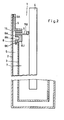
- the electrochemical storage cell 1 shown in FIG. 1 is essentially formed from a cup-shaped housing 2, a solid electrolyte 3, a current collector 4 and a closure 5.
- the cup-shaped housing 2 is made of metal and is designed as a tube closed on one side. Internally the solid electrolyte, which is also cup-shaped, is arranged in this housing.
- the embodiment of the solid electrolyte 3 shown here is made of beta aluminum oxide. The dimensions of the solid electrolyte 3 are chosen so that a continuous space 6 is formed between its outer surfaces and the inner surfaces of the metallic housing 2, which serves as one of the reactant spaces.
- the interior 7 of the solid electrolyte 3 forms the second reactant space in the exemplary embodiment described here.
- the height of the solid electrolyte 3 is selected to be slightly smaller than the height of the housing 2.
- the solid electrolyte is provided with an insulating ring 8 at its open end. This is made of alpha aluminum oxide and attached to the solid electrolyte 3 by means of a glass solder (not shown here).
- the insulating ring 8 is placed on the solid electrolyte 3 in such a way that it forms an inward and outward-facing flange 8 A or 8 I.
- the insulating ring 8 is additionally provided with an edge 8K pointing downwards. With their help, an exact centering of the insulating ring 8 on the solid electrolyte 3 is possible.
- the desired position of the insulating ring 8 on the solid electrolyte 3 is only reached when the edge 8 K lies exactly on the outer surface of the solid electrolyte 3.
- the insulating ring 8 is provided with a recess 8 N on its outward-facing side surface. This is necessary for the formation of the cell closure with the thermal compression process.
- the bond tool necessary for carrying out the thermal compression process can be supported in the recess 8N.
- the insulating ring 8 On its upward-facing side, the insulating ring 8 is provided in the center with a lip 8 L which is guided all round.
- An aluminum ring 9 A or 9 B is placed on the insulating ring 8 on both sides of the lip.
- the closure 5 of the memory cell is formed by two closure elements 5 A and 5 B.
- the first closure element 5 A has partially the shape of a cylinder, which point inwards has the flange 10. This forms the plate-shaped part of the closure element 5 A.
- the outer diameter of the cylinder is adapted to the inner diameter of the housing 2.
- the width of the flange 10 is selected so that the space 6 formed between the housing 2 and the solid electrolyte 3 is at least covered.
- the flange 10 is chosen so wide that it extends to the lip 8 L of the insulating ring 8.
- the height of the closure element 5 A, in particular of the cylinder depends on the distance between the upper end of the housing 2 and the surface of the insulating ring 8.
- the outer surfaces of the cylinder 5 A are non-positively connected to the inner surfaces of the housing 2.
- the cylinder 5 A is welded to the inner surfaces of the housing 2.
- the flange 10 is placed on the aluminum ring 9 A and non-positively connected to the insulating ring 8 by the thermal compression method.
- the closure 5 of the memory cell 1 has a second closure element 5 B. This is formed by an washer. The diameter of this ring disk is chosen so large that the interior 7 of the solid electrolyte 3 is completely covered.
- the diameter of the washer 5 B. is chosen so that its outer edge extends to the lip 8 L of the insulating ring 8. With its downward-facing edge, the washer 5 B is placed on the aluminum ring 9 B and is non-positively connected to the insulating ring 8 using the thermal compression method.
- the annular disc 5 B is penetrated centrally by the current collector 4, which protrudes into the solid electrolyte 3 and protrudes outwards via the closure 5.
- the annular disc 5 B is non-positively connected to the pantograph 4. In order to form an optimal cell seal, the edge of the ring disk, which is adjacent to the current collector 4, is pulled slightly upwards.
- the two closure elements 5 A and 5 B must in the event that the housing 2 as a pantograph serves to be electrically isolated from each other. This is done by the lip 8 L, which is molded onto the insulating ring 8. It also consists of alpha aluminum oxide and separates the two closure elements 5 A and 5 B, which are brought up to them from both sides.
- the housing 2 and the closure 5 are made of stainless steel.
- the current collector 4 is a rod made of metal.
- the interior 7 of the solid electrolyte 3 serves as a cathode space and is filled with sulfur.
- the space 6 between the housing 2 and the solid electrolyte 3 is filled with sodium and serves as an anode space.
- the metal housing 2 acts as the anodic current collector. It is of course possible to interchange the function of the two reactant spaces 6 and 7.
- FIG. 2 shows a variant of the memory cell 1 shown in FIG. 1 and explained in the associated description.
- the memory cell 1 shown here again comprises a housing 2 made of metal, a solid electrolyte 3, a current collector 4 and a closure 5.
- the solid electrolyte 3 is also provided with an insulating ring 8. This is essentially designed like the insulating ring 8 according to FIG. 1. In this case, only an insulating lip 8 L was formed.
- the closure 5 of the memory cell 1 is also formed here by two closure elements 5 A and 5 B.
- the closure element 5 A is in this case again in some areas designed as a cylinder which has an inwardly facing flange 10.
- the closure element 5 B has the shape of an annular disc.
- the diameter of the ring washer is chosen so large that its outer edge lies in one plane with the outer edge of the insulating ring. 5.
- Both closure elements 5 A and 5 B are made of aluminum.
- the closure element 5 B is arranged directly on the surface of the insulating ring 8 and is non-positively connected to it by the thermal compression method.
- the annular disc 5 B is penetrated in the middle by the current collector 4, which projects into the interior of the solid electrolyte 3 and protrudes outwards a few mm beyond the closure 5. To form a secure seal, the edge of the annular disc 5 B adjoining the current collector 4 is pulled up slightly and welded to the current collector 4.
- an annular disc 15 made of alpha aluminum oxide is placed in the area of the insulating ring 8.
- the width of the annular disc 15 corresponds approximately to the width of the insulating ring 8.
- the flange 10 of the first closure element 5A is placed on this annular disc 15.
- the width of the flange 10 is chosen so that its outer boundary is flush with the inner boundary of the insulating ring 8.
- the first closure element 5 A is also non-positively connected to the insulating ring 8 through the use of the thermal compression method.
- the connecting element 5 A is partially designed as a cylinder. The height of the cylinder is dimensioned so that the connecting element 5 A closes in one plane with the housing 2.
- the outer surface of the cylinder is non-positively connected to the inner surface of the housing 2.
- the housing 2 can also be made of aluminum.
- the interior 7 of the solid electrolyte 3 serves as the cathode space.
- the space 6 between the housing 2 and the solid electrolyte 3 forms the anode space.
- the function of the two reactant spaces 6 and 7 can also be interchanged without problems in this memory cell.
Abstract
Die Erfindung bezieht sich auf eine elektrochemische Speicherzelle (1), die einen Anodenraum (7) für die Aufnahme des Anolyten und einen Kathodenraum (6) für die Aufnahme des Katholyten besitzt. Die beiden Räume sind durch einen alkaliionenleitenden becherförmigen Festelektrolyten (3) voneinander getrennt. Der Festelektrolyt (3) wird wenigstens bereichsweise von einem metallischen Gehäuse (2) begrenzt. An seinem offenen Ende ist der Festelektrolyt (3) mit einem Isolierring (8) kraftschlüssig verbunden. In den Innenbereich des Festelektrolyten (3) ragt ein stabförmiger Stromabnehmer (4) hinein, der den Verschluß (5) der Speicherzelle (1) durchsetzt und nach außen übersteht. Der Verschluß (5) der Speicherzelle (1) wird durch wenigstens zwei Verschlußelemente (5A und 5B) gebildet, die mindestens bereichsweise plattenförmig ausgebildet sind. Ein erstes Verschlußelement (5A) ist an dem Gehäuse (2) und ein zweites Verschlußelement (5B) an dem stabförmigen Stromabnehmer (4) befestigt. Alle Verschlußelemente (5A und 5B) sind zusätzlich auf der gleichen Seite mit dem Isolierring (8) des Festelektrolyten (3) verbunden und gegeneinander isoliert.The invention relates to an electrochemical storage cell (1) which has an anode compartment (7) for receiving the anolyte and a cathode compartment (6) for receiving the catholyte. The two rooms are separated from one another by an alkali-ion-conducting, cup-shaped solid electrolyte (3). The solid electrolyte (3) is delimited at least in some areas by a metallic housing (2). At its open end, the solid electrolyte (3) is non-positively connected to an insulating ring (8). A rod-shaped current collector (4) protrudes into the inner region of the solid electrolyte (3) and penetrates the closure (5) of the storage cell (1) and protrudes outwards. The closure (5) of the memory cell (1) is formed by at least two closure elements (5A and 5B) which are plate-shaped at least in some areas. A first closure element (5A) is attached to the housing (2) and a second closure element (5B) is attached to the rod-shaped current collector (4). All closure elements (5A and 5B) are additionally connected on the same side to the insulating ring (8) of the solid electrolyte (3) and insulated from one another.
Description
Die Erfindung bezieht sich auf eine elektrochemische Speicherzelle auf der Basis von Alkalimetall und Chalkogen mit mindestens einem für die Aufnahme des Anolyten bestimmten Anodenraum und einem für die Aufnahme des Katholyten bestimmten Kathodenraum, welche durch einen alkaliionenleitenden Festelektrolyten voneinander getrennt und mindestens bereichsweise von einem metallischen Gehäuse begrenzt sind, wobei der Festelektrolyt becherförmig ausgebildet und an seinem offenen Ende mit wenigstens einem ringförmigen Isolierkörper kraftschlüssig verbunden ist, und in seinen Innenbereich ein stabförmiger Stromabnehmer hineinragt, der den Verschluß der Speicherzelle durchsetzt und nach außen übersteht.The invention relates to an electrochemical storage cell based on alkali metal and chalcogen with at least one anode compartment intended for receiving the anolyte and one cathode compartment intended for receiving the catholyte, which is separated from one another by an alkali ion-conducting solid electrolyte and at least partially delimited by a metallic housing are, the solid electrolyte is cup-shaped and is non-positively connected at its open end to at least one annular insulating body, and protrudes into its inner region a rod-shaped current collector which penetrates the closure of the storage cell and protrudes outwards.
Solche wiederaufladbaren elektrochemischen Speicherzellen mit Festelektrolyten eignen sich sehr gut zum Aufbau von Akkumulatoren hoher Energie- und Leistungsdichte. Die in den Alkali/ Chalkogen-Speicherzellen verwendeten Festelektrolyten, die beispielsweise aus Beta-Aluminiumoxid gefertigt sind, zeichnen sich dadurch aus, daß die Teilleitfähigkeit des beweglichen Ions sehr hoch und die Teilleitfähigkeit der Elektronen um viele Zenerpotenzen kleiner ist. Durch die Verwendung solcher Festelektrolyten für den Aufbau von elektrochemischen Speicherzellen wird erreicht, daß praktisch keine Selbstentladung stattfindet, da die Elektronenleitfähigkeit vernachlässigbar ist und die Reaktionssubstanzen auch nicht als neutrale Teilchen durch den Festelektrolyten gelangen können.Such rechargeable electrochemical storage cells with solid electrolytes are very suitable for building up accumulators with a high energy and power density. The solid electrolytes used in the alkali / chalcogen storage cells, which are made, for example, of beta-aluminum oxide, are distinguished by the fact that the partial conductivity of the mobile ion is very high and the partial conductivity of the electrons by many Zener powers is smaller. The use of such solid electrolytes for the construction of electrochemical memory cells means that practically no self-discharge takes place, since the electron conductivity is negligible and the reaction substances cannot pass through the solid electrolyte as neutral particles.
Ein spezielles Beispiel für solche wiederaufladbaren elektrochemischen Speicherzellen sind die auf der Basis von Natrium und Schwefel, deren Festelektrolyt aus Beta-Aluminiumoxid gefertigt ist. Ein Vorteil dieser elektrochemischen Speicherzellen besteht darin, daß beim Laden der Speicherzellen keine Nebenreaktionen auftreten. Der Grund dafür ist wiederum, daß nur eine Ionensorte durch den Festelektrolyten gelangen kann. Die Stromausbeute einer solchen Natrium/Schwefel-Speicherzelle liegt daher etwa bei 100%. Bei diesen elektrochemischen Speicherzellen ist das Verhältnis von Energieinhalt zum Gesamtgewicht einer solchen Speicherzelle im Vergleich zum Bleiakkumulator sehr hoch, da die Reaktionsstoffe leicht sind und bei der elektrochemischen Reaktion viel Energie frei wird. Elektrochemische Speicherzellen auf der Basis von Natrium und Schwefel besitzen also gegenüber von konventionellen Akkumulatoren, wie den Bleiakkumulatoren, erhebliche Vorteile.A special example of such rechargeable electrochemical storage cells are those based on sodium and sulfur, the solid electrolyte of which is made from beta aluminum oxide. An advantage of these electrochemical memory cells is that no side reactions occur when the memory cells are loaded. The reason for this is again that only one type of ion can get through the solid electrolyte. The current yield of such a sodium / sulfur storage cell is therefore around 100%. In the case of these electrochemical storage cells, the ratio of the energy content to the total weight of such a storage cell is very high in comparison to the lead accumulator, since the reactants are light and a lot of energy is released in the electrochemical reaction. Electrochemical storage cells based on sodium and sulfur therefore have considerable advantages over conventional accumulators, such as lead accumulators.
Von Nachteil ist bei diesen elektrochemischen Speicherzellen, daß sie zu ihrer Ladung auf hohen Betriebstemperaturen von etwa 300° bis 500°C gehalten werden müssen, damit die hierfür erforderlichen chemischen Reaktionen in der gewünschten Weise ablaufen. Bei diesen Temperaturen treten erhebliche Probleme bei den verwendeten Materialien auf. Insbesondere kommt es zu Unverträglichkeiten zwischen den Baumaterialien, die für die Herstellung der Speicherzelle verwendet werden und den Reaktanden, insbesondere dem Natrium und dem Schwefel. Im Verschlußbereich dieser Speicherzelle, in dem die Öffnungen der beiden Reaktandenräume aneinander grenzen, kommt es trotz der sorgfältigen Abdichtung dieser Räume gegeneinander zu Korrosionserscheinungen.The disadvantage of these electrochemical storage cells is that they have to be kept at high operating temperatures of about 300 ° to 500 ° C. for their charging, so that the chemical reactions required for this take place in the desired manner. At these temperatures, there are significant problems with the materials used. In particular, there are incompatibilities between the building materials used for the production of the storage cell and the reactants, in particular the sodium and the sulfur. In the closure area of this memory cell, in which the openings of the two If the reactant rooms are adjacent to each other, there will be signs of corrosion despite the careful sealing of these rooms against each other.
In der Patentanmeldung P 30 33 438.4 ist eine elektrochemische Speicherzelle beschrieben, bei der zur Ausbildung des Zellverschlußes das Thermo-Kompressionsverfahren Anwendung gefunden hat. Von Nachteil ist hierbei, daß für die Ausbildung dieses Verschlußes der Ringraun, der zwischen dem metallischen Gehäuse und dem Festelektrolyten.-liegt, breiter ausgebildet werden muß als normal, da der außerhalb des Festelektrolyten liegende Verschlußteil seinerseits sehr breit ist.Patent application P 30 33 438.4 describes an electrochemical storage cell in which the thermal compression method has been used to form the cell closure. The disadvantage here is that for the formation of this closure, the ring space which lies between the metallic housing and the solid electrolyte must be made wider than normal, since the closure part lying outside the solid electrolyte is itself very wide.
Der Erfindung liegt deshalb die Aufgabe zugrunde eine elektrochemische Speicherzelle zu schaffen, bei der für die Ausbildung des Zellverschlußes unter Verwendung des Thermo-Kompressionsverfahrens eine Verbreiterung des Ringraumes zwischen dem Metallgehäuse und dem Festelektrolyten vermieden wird.The invention is therefore based on the object of providing an electrochemical storage cell in which a widening of the annular space between the metal housing and the solid electrolyte is avoided for the formation of the cell closure using the thermal compression process.
Gelöst wird die Aufgabe bei einer Speicherzelle der eingangs genannten Art dadurch, daß der Verschluß wenigstens zwei Verschlußelemente umfaßt, die mindestens bereichsweise plattenförmig ausgebildet sind und wenigstens ein erstes Verschlußelement an dem Gehäuse und ein zweites Verschlußelement an dem stabförmigen Stromabnehmer befestigt ist, und daß alle Verschlußelemente zusätzlich auf der gleichen Seite mit dem Isolierring des Festelektrclyten verbunden und gegeneinander isoliert sind.The object is achieved in a storage cell of the type mentioned at the outset in that the closure comprises at least two closure elements which are at least partially plate-shaped and at least one first closure element is fastened to the housing and a second closure element is fastened to the rod-shaped current collector, and in that all the closure elements additionally connected to the insulating ring of the solid electrolyte on the same side and insulated from one another.
Erfindungsgemäß wird jedes Verschlußelement unter zwischenfügen mindestens einer Aluminium-Ringscheibe auf die Oberseite des aus Alpha-Aluminiumoxid gefertigten Isolierrings aufgelegt und mit diesem durch Anwendung des Thermo-Kompressionsverfahrens kraftschlüssig verbunden.According to the invention, each closure element is placed on the upper side of the insulating ring made of alpha aluminum oxide with the interposition of at least one aluminum ring washer and non-positively connected thereto by using the thermal compression method.
Bei einer Ausführungsform der Erfindung sind die beiden Verschlußelemente aus Edelstahl gefertigt. Das erste Verschlußelement ist als Zylinder ausgebildet, der einseitig mit einem nach innen weisenden Flansch versehen ist. Die Breite dieses Flansches ist so gewählt, daß er mindestens den Zwischenraum zwischen dem Festelektrolyten und dem Gehäuse überdeckt. Der Flansch des ersten Verschlußelementes ist über die Aluminium-Ringscheibe auf den Isolierring des Festelektrolyten aufgelegt und kraftschlüssig damit verbunden. Die Außenfläche des Zylinders ist kraftschlüssig mit der Innenfläche des metallischen Gehäuses verbunden. Das zweite Verschlußelement ist als Ringscheibe ausgebildet. Der Durchmesser der Ringscheibe ist so groß gewählt, daß durch das zweite Verschlußelement mindestens der Innenraum des Festelektrolyten überdeckt ist. Der äußere Rand der Ringscheibe ist auf der zweiten auf dem Isolierring aufliegenden Aluminium-Ringscheibe aufgelegt und über diese kraftschlüssig mit dem Isolierring verbunden.In one embodiment of the invention, the two closure elements are made of stainless steel. The first closure element is designed as a cylinder which is provided on one side with an inwardly facing flange. The width of this flange is selected so that it covers at least the space between the solid electrolyte and the housing. The flange of the first closure element is placed over the aluminum ring washer on the insulating ring of the solid electrolyte and non-positively connected to it. The outer surface of the cylinder is non-positively connected to the inner surface of the metallic housing. The second closure element is designed as an annular disk. The diameter of the ring disk is chosen so large that at least the interior of the solid electrolyte is covered by the second closure element. The outer edge of the ring disk is placed on the second aluminum ring disk resting on the insulating ring and is non-positively connected to the insulating ring.
Durch die Anordnung von Aluminium-Ringscheiben zwischen jedem der beiden Verschlußelemente und dem Isolierring ist eine kraftschlüssige Verbindung der Elemente unter Zuhilfenahme des bereits bekannten Thermokompressionsverfahrens möglich. Hierdurch wird ein Verschluß geschaffen, der insbesondere bei den in der Speicherzelle herrschenden Temperaturen und den sich bildenden Reaktionsstoffen dauerhaft beständig ist. Die beiden über jeweils eine Aluminium-Ringscheibe mit dem Isolierring des Festelektrolyten verbundenen Verschlußelemente sind vorzugsweise aus Edelstahl gefertigt. Da wie bereits oben erwähnt das erste Verschlußelement mit dem Gehäuse und das zweite Verschlußelement mit dem stabförmigen Stromabnehmer verbunden ist, müssen die beiden Verschlußelemente gegeneinander isoliert werden. Dies geschieht durch eine Lippe, die auf der Oberseite des Isolierrings angefcrmt ist. Die Lippe ist etwa mittig auf dem Isolierring angeordnet und rundum geführt. Die äußeren Begrenzungskanten der Verschlußelemente sind von beiden Seiten bis an diese Lippe herangeführt. Die Lippe ist ebenfalls aus Alpha-Aluminiumxid gefertigt, so daß zwischen den beiden Verschlußelementen keine elektrisch leitende Verbindung möglich ist.The arrangement of aluminum washers between each of the two closure elements and the insulating ring enables a force-fit connection of the elements with the aid of the already known thermocompression method. This creates a closure that is permanently stable, in particular at the temperatures prevailing in the storage cell and the reactants that form. The two closure elements, each connected to the insulating ring of the solid electrolyte via an aluminum washer, are preferably made of stainless steel. Since, as already mentioned above, the first closure element is connected to the housing and the second closure element is connected to the rod-shaped current collector, the two closure elements must be insulated from one another. This is done through a lip that is crimped on the top of the insulating ring. The lip is arranged approximately in the middle of the insulating ring and guided all around. The outer loading boundary edges of the closure elements are brought up to this lip from both sides. The lip is also made of alpha aluminum oxide, so that no electrically conductive connection is possible between the two closure elements.
Bei einer Ausführungsform der Erfindung ist der Isolierring an seiner nach außen weisenden Seite mit einer Ausnehmung versehen. In dieser Ausnehmung kann das für die Durchführung des Thermo-Kompressionsverfahrens notwendige Bond-Werkzeug abstützt werden.In one embodiment of the invention, the insulating ring is provided with a recess on its outward-facing side. The bond tool necessary for carrying out the thermal compression process can be supported in this recess.
Bei einer weiteren Ausführungsform der Erfindung sind beide Verschlußelemente aus Aluminium gefertigt. Hierbei wird das zweite Verschlußelement direkt auf den Isolierring des Festelektrolyten aufgelegt und mit Hilfe des Thermo-Kompressionsverfahrens kraftschlüssig mit diesem verbunden. Das erste Verschlußelement wird unter zwischenfügen einer Alpha-Aluminium-ringscheibe auf das zweite Verschlußelement aufgelegt und ebenfalls durch Anwendung des Thermo-Kompressionsverfahrens kraftschlüssig mit diesem verbunden.In a further embodiment of the invention, both closure elements are made of aluminum. In this case, the second closure element is placed directly on the insulating ring of the solid electrolyte and non-positively connected to it with the aid of the thermal compression process. The first closure element is placed on the second closure element with the interposition of an alpha-aluminum washer and also non-positively connected to it by using the thermal compression method.
In vorteilhafter Weise kann eine Speicherzelle mit einem solchen Verschluß mit einem geringeren Durchmesser hergestellt, und unter Zuhilfenahme des Thermo-Kompressionsverfahrens verschlossen werden, als es bei herkömmlichen Speicherzellen möglich ist. Dies ist besonders bei inversen Speicherzellen, bei denen der Schwefel innerhalb des Festelektrolyten und das Natrium innerhalb des Ringraumes angeordnet ist, sehr wichtig, da hierbei wegen der geringeren Zellkapazität der Durchmesser des Metallgehäuses bei Verwendung der erfindungsgemäßen Speicherzelle beträchtlich kleiner gemacht werden kann.In an advantageous manner, a memory cell with such a closure can be produced with a smaller diameter and can be closed with the aid of the thermal compression process than is possible with conventional memory cells. This is particularly important in the case of inverse memory cells in which the sulfur is arranged within the solid electrolyte and the sodium is arranged within the annular space, since the diameter of the metal housing can be made considerably smaller when using the memory cell according to the invention because of the lower cell capacity.
Durch den geringeren Durchmesser der Speicherzellen ist es außerdem möglich, eine größere Anzahl von Speicherzellen in einer Batterie unterzubringen, beziehungsweise die Batterie kann bei gleichbleibender Anzahl von Speicherzellen kleiner ausgebildet werden. Ein weiterer Vorteil ergibt sich bei der erfindungsgemäßen Speicherzelle für die Verbindung des Isolierrings mit dem Festelektrolyten. Da der Isolierring aus Alpha-Aluminiumoxid gefertigt ist, wird er vorzugsweise durch ein Glaslot am Festelektrolyten befestigt. Da bei den hier beschriebenen Ausführungsformen der erfindungsgemäßen Speicherzelle die Verschlußelemente alle mit der Oberseite des Isolierrings verbunden sind, braucht die Unterseite des Isolierrings nach der Anglasung nicht mehr so sorgfältig wie bisher von dem Glaslot gereinigt zu werden, da dort keine weiteren Bauteile der Speicherzelle befestigt werden.The smaller diameter of the memory cells also makes it possible to insert a larger number of memory cells to accommodate a battery, or the battery can be made smaller with the same number of memory cells. A further advantage results in the memory cell according to the invention for connecting the insulating ring to the solid electrolyte. Since the insulating ring is made of alpha aluminum oxide, it is preferably attached to the solid electrolyte by a glass solder. Since in the embodiments of the memory cell according to the invention described here, the closure elements are all connected to the top of the insulating ring, the underside of the insulating ring does not need to be cleaned as carefully as before from the glass solder, since no further components of the memory cell are attached there .
Ein weiterer Vorteil der erfindungsgemäßen Speicherzelle ergibt sich für die Groß-Serien-Herstellung. Bei der Ausbildung des Verschlusses müssen die Metallteile nur von einer Seite zugeführt werden. Das Gleiche gilt für die Ausübung der Druckkraft, die bei der Verbindung der Bauteile durch das Thermo-Kompressionsverfahren erforderlich ist.Another advantage of the memory cell according to the invention results for large-scale production. When forming the closure, the metal parts only have to be fed from one side. The same applies to the application of the compressive force that is required when connecting the components using the thermal compression process.
Nachfolgend wird die Erfindung anhand von Zeichnungen erläutert.The invention is explained below with reference to drawings.
Es zeigen: .
- Fig. 1 eine Speicherzelle im Vertikalschnitt,
- Fig. 2 eine Variante der in Fig. 1 gezeigten Speicherzelle ebenfalls im Vertikalschnitt.
- 1 is a memory cell in vertical section,
- Fig. 2 shows a variant of the memory cell shown in Fig. 1 also in vertical section.
Die in Fig. 1 dargestellte elektrochemische Speicherzelle 1 wird im wesentlichen aus einem becherförmigen Gehäuse 2, einem Festelektrolyten 3, einem Stromabnehmer 4 und einem Verschluß 5 gebildet. Das becherförmige Gehäuse 2 ist aus Metall hergestellt und als einseitig geschlossenes Rohr ausgebildet. Im Inneren dieses Gehäuses ist der ebenfalls becherförmig ausgebildete Festelektrolyt angeordnet. Die hier gezeigte Ausführungsform des Festelektrolyten 3 ist aus Beta-Aluminiumoxid hergestellt. Die Abmessungen des Festelektrolyten 3 sind so gewählt, daß zwischen seinen Aussenflächen und den Innenflächen des metallischen Gehäuses 2 ein zusammenhängender Zwischenraum 6 gebildet wird, der als einer der Reaktandenräume dient. Der Innenraum 7 des Festelektrolyten 3 bildet bei dem hier beschriebenen Ausführungsbeispiel den zweiten Reaktandenraum. Die Höhe des Festelektrolyten 3 ist geringfügig kleiner gewählt als die Höhe des Gehäuses 2. An seinem offenen Ende ist der Festelektrolyt mit einem Isolierring 8 versehen. Dieser ist aus Alpha-Aluminiumoxid hergestellt und mittels eines Glaslotes (hier nicht dargestellt) an dem Festelektrolyten 3 befestigt. Der Isolierring-8 ist so auf den Festelektrolyten 3 aufgesetzt, daß er einen nach innen und aussen weisenden Flansch 8 A beziehungsweise 8 I bildet. Der Isolierring 8 ist zusätzlich mit einer nach unten weisenden Kante 8 K versehen. Mit deren Hilfe ist eine genaue Zentrierung des Isolierringes 8 auf dem Festelektrolyten 3 möglich. Erst wenn die Kante 8 K exakt an der Aussenfläche des Festelektrolyten 3 anliegt, ist die gewünschte Position des Isolierringes 8 auf dem Festelektrolyten 3 erreicht. An seiner nach aussen weisenden Seitenfläche ist der Isolierring 8 mit einer Ausnehmung 8 N versehen. Diese ist für die Ausbildung des Zellverschlußes mit dem Thermo-Kompressionsverfahren erforderlich. In der Ausnehmung 8N kann das für die Durchführung des Thermo-Kompressionsverfahrens notwendige Bond-Werkzeug abgestützt werden. Auf seiner nach oben weisenden Seite ist der Isolierring 8 mittig mit einer rundum geführten Lippe 8 L versehen. Beidseitig der Lippe ist jeweils ein Aluminiumring 9 A beziehungsweise 9 B auf den Isolierring 8 aufgelegt.The
Der Verschluß 5 der Speicherzelle wird durch zwei Verschlußelemente 5 A und 5 B gebildet. Das erste Verschlußelement 5 A hat teilweise die Form eines Zylinders, der einen nach innen weisenden Flansch 10 besitzt. Dieser bildet den plattenförmigen Teil des Verschlußelementes 5 A. Der Aussendurchmesser des Zylinders ist an den Innendurchmesser des Gehäuses 2 angepaßt. Die Breite des Flansches 10 ist so gewählt, daß der zwischen dem Gehäuse 2 und dem Festelektrolyten 3 gebildete Zwischenraum 6 mindestens überdeckt wird. Vorzugsweise ist der Flansch 10 so breit gewählt, daß er bis zur Lippe 8 L des Isolierringes 8 reicht. Die Höhe des Verschlußelementes 5 A insbesondere des Zylinders richtet sich nach dem Abstand zwischen dem oberen Ende des Gehäuses 2 und der Oberfläche des Isolierringes 8. Die Aussenflächen des Zylinders 5 A sind mit den Innenflächen des Gehäuses 2 kraftschlüssig verbunden. Insbesondere ist der Zylinder 5 A mit den Innenflächen des Gehäuses 2 verschweißt. Der Flansch 10 ist auf den Aluminiumring 9 A aufgesetzt und durch das Thermo-Kompressionsverfahren kraftschlüssig mit dem Isolierring 8 verbunden. Wie bereits oben erwähnt, weist der Verschluß 5 der Speicherzelle 1 ein zweites Verschlußelement 5 B auf. Dieses wird durch eine Ringscheibe gebildet. Der Durchmesser dieser Ringscheibe ist so groß gewählt, daß der Innenraum 7 des Festelektrolyten 3 vollständig überdeckt wird.The
Vorzugsweise wird der Durchmesser der Ringscheibe 5 B.so gewählt, daß ihre Aussenkante bis zur Lippe 8 L des Isolierringes 8 reicht. Mit ihrem nach unten weisenden Rand ist die Ringscheibe 5 B auf den Aluminiumring 9 B aufgesetzt und unter Anwendung des Thermo-Kompressionsverfahrens mit dem Isolierring 8 kraftschlüssig verbunden. Die Ringscheibe 5 B wird mittig von dem Stromabnehmer 4 durchsetzt, der in den Festelektrolyten 3 hineinragt und über den Verschluß 5 nach aussen übersteht. Die Ringscheibe 5 B ist kraftschlüssig mit dem Stromabnehmer 4 verbunden. Zur Ausbildung einer optimalen Zellabdichtung ist der Rand der Ringscheibe, der an den Stromabnehmer 4 angrenzt geringfügig nach oben gezogen. Die beiden Verschlußelemente 5 A und 5 B müssen für den Fall, daß das Gehäuse 2 als Stromabnehmer dient gegeneinander elektrisch isoliert sein. Dies geschieht durch die Lippe 8 L, die an den Isolierring 8 angeformt ist. Sie besteht ebenfalls aus Alpha-Aluminiumoxid und trennt die beiden Verschlußelemente 5 A und 5 B, die von beiden Seiten an sie herangeführt sind. Bei dem hier gezeigten Ausführungsbeispiel sind das Gehäuse 2 und der Verschluß 5 aus Edelstahl gefertigt. Bei dem Stromabnehmer 4 handelt es sich um einen aus Metall gefertigten Stab. Bei dem hier gezeigten Ausführungsbeispiel dient der Innenraum 7 des Festelektrolyten 3 als Kathodenraum und ist mit Schwefel gefüllt. Der zwischen dem Gehäuse 2 und dem Festelektrolyten 3 liegende Raum 6 ist mit Natrium gefüllt und dient als Anodenraum. Als anodischer Stromabnehmer fungiert hierbei das Metallgehäuse 2. Eine Vertauschung der Funktion der beiden Reaktandenräume 6 und 7 ist selbstverständlich möglich.Preferably, the diameter of the
Fig. 2 zeigt eine Variante der in Fig. 1 dargestellten und in der dazugehörigen Beschreibung erläuterten Speicherzelle 1. Die hier dargestellte Speicherzelle 1 umfaßt wiederum ein Gehäuse 2 aus Metall, einen Festelektrolyten 3, einen Stromabnehmer 4 und einen Verschluß 5. Der Festelektrolyt 3 ist ebenfalls mit einem Isolierring 8 versehen. Dieser ist im wesentlichen wie der Isolierring 8 nach Fig. 1 ausgebildet. Hierbei wurde lediglich auf die Anformung einer Isolierlippe 8 L verzichtet. Der Verschluß 5 der Speicherzelle 1 wird auch hierbei durch zwei Verschlußelemente 5 A und 5 B gebildet. Das Verschlußelement 5 A ist auch hierbei wiederum bereichsweise als Zylinder ausgebildet,der einen nach innen weisenden Flansch 10 besitzt. Das Verschlußelement 5 B hat die Form einer Ringscheibe. Der Durchmesser der Ringscheibe ist so groß gewählt, daß ihre äußere Kante in einer Ebene mit dem äußeren Rand des Isolierringes.5 liegt. Beide Verschlußelemente 5 A und 5 B sind aus Aluminium gefertigt. Das Verschlußelement 5 B ist direkt auf der Oberfläche des Isolierringes 8 angeordnet und durch dasThermo-Kompressionsverfahren mit diesem kraftschlüssig verbunden. Die Ringscheibe 5 B wird mittig von dem Stromabnehmer 4 durchsetzt, der in das Innere des Festelektrolyten 3 hineinragt und nach aussen einige mm über den Verschluß 5 übersteht. Zur Ausbildung einer sicheren Abdichtung ist der an den Stromabnehmer 4 angrenzende Rand der Ringscheibe 5 B geringfügig nach oben gezogen und mit dem Stromabnehmer 4 verschweißt. Auf die Oberseite der Ringseite 5 B ist im Bereich des Isolierringes 8 eine Ringscheibe 15 aus Alpha-Aluminiumoxid aufgelegt. Die Breite der Ringscheibe 15 entspricht in etwa der Breite des Isolierringes 8. Auf diese Ringscheibe 15 ist der Flansch 10 des ersten Verschlußelementes 5Aaufgesetzt. Die Breite des Flansches 10 ist so gewählt, daß seine äußere Begrenzung in einer Ebene mit der inneren Begrenzung des Isolierringes 8 abschließt. Das erste Verschlußelement 5 A ist ebenfalls durch die Anwendung des Thermo-Kompressionsverfahrens mit dem Isolierring 8 kraftschlüssig verbunden. Wie bereits oben erwähnt ist das Verbindungselement 5 A bereichsweise als Zylinder ausgebildet. Die Höhe des Zylinders ist so bemessen, daß das Verbindungselement 5 A in einer Ebene mit dem Gehäuse 2 abschließt. Die Außenfläche des Zylinders ist mit der Innenfläche des Gehäuses 2 kraftschlüssig verbunden. Bei dem hier beschriebenen Ausführungsbeispiel kann auch das Gehäuses 2 aus Aluminium hergestellt sein. Der Innenraum 7 des Festelektrolyten 3 dient hierbei als Kathodenraum. Der Raum 6 zwischen dem Gehäuse 2 und dem Festelektrolyten 3 bildet den Anodenraum. Die Funktion der beiden Reaktandenräume 6 und 7 kann auch bei dieser Speicherzelle problemlos vertauscht werden.FIG. 2 shows a variant of the
Claims (16)
Applications Claiming Priority (2)
| Application Number | Priority Date | Filing Date | Title |
|---|---|---|---|
| DE19813117383 DE3117383A1 (en) | 1981-05-02 | 1981-05-02 | "ELECTROCHEMICAL STORAGE CELL" |
| DE3117383 | 1981-05-02 |
Publications (2)
| Publication Number | Publication Date |
|---|---|
| EP0064656A1 true EP0064656A1 (en) | 1982-11-17 |
| EP0064656B1 EP0064656B1 (en) | 1985-09-18 |
Family
ID=6131286
Family Applications (1)
| Application Number | Title | Priority Date | Filing Date |
|---|---|---|---|
| EP82103506A Expired EP0064656B1 (en) | 1981-05-02 | 1982-04-26 | Electrochemical storage cell |
Country Status (4)
| Country | Link |
|---|---|
| US (1) | US4473624A (en) |
| EP (1) | EP0064656B1 (en) |
| JP (1) | JPS57187875A (en) |
| DE (1) | DE3117383A1 (en) |
Cited By (5)
| Publication number | Priority date | Publication date | Assignee | Title |
|---|---|---|---|---|
| EP0142030A2 (en) * | 1983-11-09 | 1985-05-22 | Asea Brown Boveri Aktiengesellschaft | Electrochemical storage cell |
| EP0158815A1 (en) * | 1984-04-02 | 1985-10-23 | BROWN, BOVERI & CIE Aktiengesellschaft | Electrochemical storage cell |
| EP0166605A2 (en) * | 1984-06-26 | 1986-01-02 | Chloride Silent Power Limited | Sodium sulphur cells and their manufacture |
| WO1989004069A1 (en) * | 1987-10-23 | 1989-05-05 | Chloride Silent Power Limited | Method of and apparatus for constructing an alkali metal energy conversion device |
| WO1989004068A1 (en) * | 1987-10-23 | 1989-05-05 | Chloride Silent Power Limited | Alkali metal energy conversion device and method of construction |
Families Citing this family (2)
| Publication number | Priority date | Publication date | Assignee | Title |
|---|---|---|---|---|
| DE4336236C1 (en) * | 1993-10-23 | 1995-01-05 | Abb Patent Gmbh | Electrochemical storage cell |
| GB9604133D0 (en) * | 1996-02-27 | 1996-05-01 | Programme 3 Patent Holdings | Electrochemical cell |
Citations (6)
| Publication number | Priority date | Publication date | Assignee | Title |
|---|---|---|---|---|
| FR2315778A1 (en) * | 1975-07-02 | 1977-01-21 | United Kingdom Government | Multicell electric battery - with solid electrolytes and alloy steel electrode separating adjacent cells for series or parallel connection |
| FR2327647A1 (en) * | 1975-10-10 | 1977-05-06 | Chloride Silent Power Ltd | METAL ALKALINE / SULFUR TYPE BATTERY ELEMENTS AND THEIR MANUFACTURING PROCESS |
| GB1502693A (en) * | 1976-02-09 | 1978-03-01 | Chloride Silent Power Ltd | Sealing of electro-chemical devices utilising liquid sodium and a solid ceramic electrolyte permeable to sodium ion |
| US4105834A (en) * | 1976-10-14 | 1978-08-08 | Baker Derrick John | Electric cells |
| US4197363A (en) * | 1978-10-26 | 1980-04-08 | Ford Motor Company | Seal for sodium sulfur battery |
| EP0018190A1 (en) * | 1979-04-19 | 1980-10-29 | Chloride Silent Power Limited | Glass seals for sealing beta-alumina in electro-chemical cells or other energy conversion devices, glasses for use in such seals and cells or other energy conversion devices with such seals |
Family Cites Families (10)
| Publication number | Priority date | Publication date | Assignee | Title |
|---|---|---|---|---|
| US2544115A (en) * | 1945-12-22 | 1951-03-06 | Glenside Bag Company | Leakproof battery |
| US3939007A (en) * | 1973-01-16 | 1976-02-17 | British Railways Board | Sodium sulphur cells |
| US4129690A (en) * | 1974-02-15 | 1978-12-12 | The Electricity Council | Sodium sulphur cells |
| US4124739A (en) * | 1974-11-28 | 1978-11-07 | Chloride Silent Power Ltd. | Alkali metal-sulphur cells |
| FR2333358A1 (en) * | 1975-11-28 | 1977-06-24 | Comp Generale Electricite | SULFUR-SODIUM ELECTROCHEMICAL GENERATOR |
| US4052533A (en) * | 1976-03-29 | 1977-10-04 | Union Carbide Corporation | Pressure relief flapper vent valve for galvanic cells |
| JPS5446626A (en) * | 1977-09-21 | 1979-04-12 | Nippon Gakki Seizo Kk | Racket |
| US4234668A (en) * | 1978-04-20 | 1980-11-18 | General Electric Company | Composite sulfur electrode container and method of manufacture |
| US4192911A (en) * | 1978-11-01 | 1980-03-11 | Ford Motor Company | Sodium sulfur battery seal |
| DE3114348A1 (en) * | 1981-04-09 | 1982-11-04 | Brown, Boveri & Cie Ag, 6800 Mannheim | "RECHARGEABLE GALVANIC SINGLE CELL" |
-
1981
- 1981-05-02 DE DE19813117383 patent/DE3117383A1/en active Granted
-
1982
- 1982-04-23 US US06/371,124 patent/US4473624A/en not_active Expired - Fee Related
- 1982-04-26 EP EP82103506A patent/EP0064656B1/en not_active Expired
- 1982-04-30 JP JP57073273A patent/JPS57187875A/en active Pending
Patent Citations (6)
| Publication number | Priority date | Publication date | Assignee | Title |
|---|---|---|---|---|
| FR2315778A1 (en) * | 1975-07-02 | 1977-01-21 | United Kingdom Government | Multicell electric battery - with solid electrolytes and alloy steel electrode separating adjacent cells for series or parallel connection |
| FR2327647A1 (en) * | 1975-10-10 | 1977-05-06 | Chloride Silent Power Ltd | METAL ALKALINE / SULFUR TYPE BATTERY ELEMENTS AND THEIR MANUFACTURING PROCESS |
| GB1502693A (en) * | 1976-02-09 | 1978-03-01 | Chloride Silent Power Ltd | Sealing of electro-chemical devices utilising liquid sodium and a solid ceramic electrolyte permeable to sodium ion |
| US4105834A (en) * | 1976-10-14 | 1978-08-08 | Baker Derrick John | Electric cells |
| US4197363A (en) * | 1978-10-26 | 1980-04-08 | Ford Motor Company | Seal for sodium sulfur battery |
| EP0018190A1 (en) * | 1979-04-19 | 1980-10-29 | Chloride Silent Power Limited | Glass seals for sealing beta-alumina in electro-chemical cells or other energy conversion devices, glasses for use in such seals and cells or other energy conversion devices with such seals |
Cited By (15)
| Publication number | Priority date | Publication date | Assignee | Title |
|---|---|---|---|---|
| EP0142030A3 (en) * | 1983-11-09 | 1986-12-03 | Brown, Boveri & Cie Aktiengesellschaft | Electrochemical storage cell |
| EP0142030A2 (en) * | 1983-11-09 | 1985-05-22 | Asea Brown Boveri Aktiengesellschaft | Electrochemical storage cell |
| EP0158815A1 (en) * | 1984-04-02 | 1985-10-23 | BROWN, BOVERI & CIE Aktiengesellschaft | Electrochemical storage cell |
| US4759999A (en) * | 1984-06-26 | 1988-07-26 | Chloride Silent Power Limited | Sodium sulphur cells and their manufacture |
| EP0166605A3 (en) * | 1984-06-26 | 1987-03-25 | Chloride Silent Power Limited | Sodium sulphur cells and their manufacture |
| AU573853B2 (en) * | 1984-06-26 | 1988-06-23 | Chloride Silent Power Ltd. | Sodium sulphide cell having lid sealed to case by thermocompression bonding |
| EP0166605A2 (en) * | 1984-06-26 | 1986-01-02 | Chloride Silent Power Limited | Sodium sulphur cells and their manufacture |
| WO1989004069A1 (en) * | 1987-10-23 | 1989-05-05 | Chloride Silent Power Limited | Method of and apparatus for constructing an alkali metal energy conversion device |
| WO1989004068A1 (en) * | 1987-10-23 | 1989-05-05 | Chloride Silent Power Limited | Alkali metal energy conversion device and method of construction |
| GB2230378A (en) * | 1987-10-23 | 1990-10-17 | Chloride Silent Power Ltd | Method of and apparatus for constructing an alkali metal energy conversion device |
| GB2231712A (en) * | 1987-10-23 | 1990-11-21 | Chloride Silent Power Ltd | Alkali metal energy conversion device and method of construction |
| GB2230378B (en) * | 1987-10-23 | 1991-03-27 | Chloride Silent Power Ltd | Apparatus for constructing an alkali metal energy conversion device |
| GB2231712B (en) * | 1987-10-23 | 1991-07-17 | Chloride Silent Power Ltd | Alkali metal energy conversion device and method of construction |
| US5075957A (en) * | 1987-10-23 | 1991-12-31 | Chloride Silent Power, Limited | Apparatus for constructing an alkali metal energy conversion device |
| US5118574A (en) * | 1987-10-23 | 1992-06-02 | Chloride Silent Power Limited | Alkali metal energy conversion device and method of construction |
Also Published As
| Publication number | Publication date |
|---|---|
| EP0064656B1 (en) | 1985-09-18 |
| DE3117383A1 (en) | 1982-11-18 |
| US4473624A (en) | 1984-09-25 |
| DE3117383C2 (en) | 1988-03-31 |
| JPS57187875A (en) | 1982-11-18 |
Similar Documents
| Publication | Publication Date | Title |
|---|---|---|
| DE3340079C2 (en) | ||
| DE3033438C2 (en) | Electrochemical storage cell | |
| DE3420585A1 (en) | BIPOLAR METAL AIR OXYGEN BATTERY WITH A SELF-PRESERVED ANODE | |
| DE2803211A1 (en) | ELECTROCHEMICAL CELL AND CATHODE FOR IT | |
| EP0064234B1 (en) | Electrochemical storage cell | |
| EP0142030B1 (en) | Electrochemical storage cell | |
| EP0064676B1 (en) | Electrochemical storage cell | |
| EP0064656B1 (en) | Electrochemical storage cell | |
| EP0064655A1 (en) | By-pass element | |
| DE3102771C2 (en) | Electric battery with a layer structure | |
| EP0079582B1 (en) | Electrochemical storage cell | |
| EP0158815B1 (en) | Electrochemical storage cell | |
| DE2312819C3 (en) | Galvanic gas-depolarized element | |
| DE2652012C2 (en) | Electrochemical generator based on sulfur-sodium | |
| DE3631965C2 (en) | Method for producing a connection bushing for a battery consisting of cells stacked one on top of the other | |
| DE3039013A1 (en) | ELECTROCHEMICAL GENERATOR | |
| WO2003094264A2 (en) | Molten carbonate fuel cell and method for production thereof | |
| EP0187305B1 (en) | Electrochemical storage cell | |
| DE3150702C2 (en) | Method for producing an electrochemical storage cell and a storage cell produced by this method | |
| EP0077538B1 (en) | Electrochemical storage cell | |
| DE3248110A1 (en) | Electrochemical storage cell | |
| DE3615239A1 (en) | Electrochemical storage cell | |
| DE3108188A1 (en) | LEAD ACCUMULATOR | |
| DE3338955A1 (en) | Electrochemical storage cell | |
| DE2803212A1 (en) | Anode made of prismatic alkali metal for primary cells - has mesh shaped substrate with adhering metallic layers on both faces |
Legal Events
| Date | Code | Title | Description |
|---|---|---|---|
| PUAI | Public reference made under article 153(3) epc to a published international application that has entered the european phase |
Free format text: ORIGINAL CODE: 0009012 |
|
| AK | Designated contracting states |
Designated state(s): BE FR GB IT NL |
|
| 17P | Request for examination filed |
Effective date: 19830409 |
|
| GRAA | (expected) grant |
Free format text: ORIGINAL CODE: 0009210 |
|
| AK | Designated contracting states |
Designated state(s): BE FR GB IT NL |
|
| ITF | It: translation for a ep patent filed |
Owner name: MODIANO & ASSOCIATI S.R.L. |
|
| ET | Fr: translation filed | ||
| PG25 | Lapsed in a contracting state [announced via postgrant information from national office to epo] |
Ref country code: BE Effective date: 19860430 |
|
| PLBE | No opposition filed within time limit |
Free format text: ORIGINAL CODE: 0009261 |
|
| STAA | Information on the status of an ep patent application or granted ep patent |
Free format text: STATUS: NO OPPOSITION FILED WITHIN TIME LIMIT |
|
| 26N | No opposition filed | ||
| BERE | Be: lapsed |
Owner name: BROWN BOVERI & CIE A.G. Effective date: 19860430 |
|
| PGFP | Annual fee paid to national office [announced via postgrant information from national office to epo] |
Ref country code: GB Payment date: 19900228 Year of fee payment: 9 |
|
| PGFP | Annual fee paid to national office [announced via postgrant information from national office to epo] |
Ref country code: FR Payment date: 19900323 Year of fee payment: 9 |
|
| ITTA | It: last paid annual fee | ||
| PGFP | Annual fee paid to national office [announced via postgrant information from national office to epo] |
Ref country code: NL Payment date: 19900430 Year of fee payment: 9 |
|
| PG25 | Lapsed in a contracting state [announced via postgrant information from national office to epo] |
Ref country code: GB Effective date: 19910426 |
|
| PG25 | Lapsed in a contracting state [announced via postgrant information from national office to epo] |
Ref country code: NL Effective date: 19911101 |
|
| NLV4 | Nl: lapsed or anulled due to non-payment of the annual fee | ||
| PG25 | Lapsed in a contracting state [announced via postgrant information from national office to epo] |
Ref country code: FR Effective date: 19911230 |
|
| GBPC | Gb: european patent ceased through non-payment of renewal fee | ||
| REG | Reference to a national code |
Ref country code: FR Ref legal event code: ST |