EP0064652A2 - Anchoring element for fibre-compound materials - Google Patents
Anchoring element for fibre-compound materials Download PDFInfo
- Publication number
- EP0064652A2 EP0064652A2 EP82103491A EP82103491A EP0064652A2 EP 0064652 A2 EP0064652 A2 EP 0064652A2 EP 82103491 A EP82103491 A EP 82103491A EP 82103491 A EP82103491 A EP 82103491A EP 0064652 A2 EP0064652 A2 EP 0064652A2
- Authority
- EP
- European Patent Office
- Prior art keywords
- rod
- bore
- element according
- fiber composite
- force application
- Prior art date
- Legal status (The legal status is an assumption and is not a legal conclusion. Google has not performed a legal analysis and makes no representation as to the accuracy of the status listed.)
- Granted
Links
- 238000004873 anchoring Methods 0.000 title claims description 13
- 239000000463 material Substances 0.000 title description 4
- 239000000835 fiber Substances 0.000 claims abstract description 28
- 239000002131 composite material Substances 0.000 claims abstract description 23
- 150000001875 compounds Chemical class 0.000 claims abstract description 14
- 238000007789 sealing Methods 0.000 claims abstract description 5
- 238000005266 casting Methods 0.000 claims description 11
- 229920005989 resin Polymers 0.000 claims description 8
- 239000011347 resin Substances 0.000 claims description 8
- 229920001971 elastomer Polymers 0.000 claims description 2
- 239000000806 elastomer Substances 0.000 claims description 2
- 239000011159 matrix material Substances 0.000 claims description 2
- 239000000853 adhesive Substances 0.000 description 4
- 230000001070 adhesive effect Effects 0.000 description 4
- 229920006337 unsaturated polyester resin Polymers 0.000 description 4
- 238000005452 bending Methods 0.000 description 3
- 230000005540 biological transmission Effects 0.000 description 3
- 230000000694 effects Effects 0.000 description 3
- 239000003822 epoxy resin Substances 0.000 description 3
- 239000003365 glass fiber Substances 0.000 description 3
- 238000004519 manufacturing process Methods 0.000 description 3
- 238000000034 method Methods 0.000 description 3
- 229920000647 polyepoxide Polymers 0.000 description 3
- 238000004382 potting Methods 0.000 description 3
- 238000009864 tensile test Methods 0.000 description 3
- VYPSYNLAJGMNEJ-UHFFFAOYSA-N Silicium dioxide Chemical compound O=[Si]=O VYPSYNLAJGMNEJ-UHFFFAOYSA-N 0.000 description 2
- 230000006978 adaptation Effects 0.000 description 2
- 238000005553 drilling Methods 0.000 description 2
- LNEPOXFFQSENCJ-UHFFFAOYSA-N haloperidol Chemical compound C1CC(O)(C=2C=CC(Cl)=CC=2)CCN1CCCC(=O)C1=CC=C(F)C=C1 LNEPOXFFQSENCJ-UHFFFAOYSA-N 0.000 description 2
- 239000002184 metal Substances 0.000 description 2
- 229910052751 metal Inorganic materials 0.000 description 2
- 230000003068 static effect Effects 0.000 description 2
- GLGNXYJARSMNGJ-VKTIVEEGSA-N (1s,2s,3r,4r)-3-[[5-chloro-2-[(1-ethyl-6-methoxy-2-oxo-4,5-dihydro-3h-1-benzazepin-7-yl)amino]pyrimidin-4-yl]amino]bicyclo[2.2.1]hept-5-ene-2-carboxamide Chemical compound CCN1C(=O)CCCC2=C(OC)C(NC=3N=C(C(=CN=3)Cl)N[C@H]3[C@H]([C@@]4([H])C[C@@]3(C=C4)[H])C(N)=O)=CC=C21 GLGNXYJARSMNGJ-VKTIVEEGSA-N 0.000 description 1
- 229920000049 Carbon (fiber) Polymers 0.000 description 1
- 239000006004 Quartz sand Substances 0.000 description 1
- 238000004026 adhesive bonding Methods 0.000 description 1
- 239000004917 carbon fiber Substances 0.000 description 1
- 229910010293 ceramic material Inorganic materials 0.000 description 1
- 229940125758 compound 15 Drugs 0.000 description 1
- 229940125898 compound 5 Drugs 0.000 description 1
- 230000008602 contraction Effects 0.000 description 1
- 238000005260 corrosion Methods 0.000 description 1
- 230000007797 corrosion Effects 0.000 description 1
- 239000000945 filler Substances 0.000 description 1
- 239000007769 metal material Substances 0.000 description 1
- 150000002739 metals Chemical class 0.000 description 1
- 239000000203 mixture Substances 0.000 description 1
- 239000004033 plastic Substances 0.000 description 1
- 229920003023 plastic Polymers 0.000 description 1
- 229920001225 polyester resin Polymers 0.000 description 1
- 239000004645 polyester resin Substances 0.000 description 1
- 229920005749 polyurethane resin Polymers 0.000 description 1
- 239000000843 powder Substances 0.000 description 1
- 230000002028 premature Effects 0.000 description 1
- 238000007639 printing Methods 0.000 description 1
- 239000010453 quartz Substances 0.000 description 1
- 238000007493 shaping process Methods 0.000 description 1
- 239000007858 starting material Substances 0.000 description 1
- 238000003466 welding Methods 0.000 description 1
Images

Classifications
-
- E—FIXED CONSTRUCTIONS
- E04—BUILDING
- E04C—STRUCTURAL ELEMENTS; BUILDING MATERIALS
- E04C5/00—Reinforcing elements, e.g. for concrete; Auxiliary elements therefor
- E04C5/08—Members specially adapted to be used in prestressed constructions
- E04C5/12—Anchoring devices
- E04C5/125—Anchoring devices the tensile members are profiled to ensure the anchorage, e.g. when provided with screw-thread, bulges, corrugations
-
- F—MECHANICAL ENGINEERING; LIGHTING; HEATING; WEAPONS; BLASTING
- F16—ENGINEERING ELEMENTS AND UNITS; GENERAL MEASURES FOR PRODUCING AND MAINTAINING EFFECTIVE FUNCTIONING OF MACHINES OR INSTALLATIONS; THERMAL INSULATION IN GENERAL
- F16B—DEVICES FOR FASTENING OR SECURING CONSTRUCTIONAL ELEMENTS OR MACHINE PARTS TOGETHER, e.g. NAILS, BOLTS, CIRCLIPS, CLAMPS, CLIPS OR WEDGES; JOINTS OR JOINTING
- F16B13/00—Dowels or other devices fastened in walls or the like by inserting them in holes made therein for that purpose
- F16B13/14—Non-metallic plugs or sleeves; Use of liquid, loose solid or kneadable material therefor
- F16B13/141—Fixing plugs in holes by the use of settable material
-
- F—MECHANICAL ENGINEERING; LIGHTING; HEATING; WEAPONS; BLASTING
- F16—ENGINEERING ELEMENTS AND UNITS; GENERAL MEASURES FOR PRODUCING AND MAINTAINING EFFECTIVE FUNCTIONING OF MACHINES OR INSTALLATIONS; THERMAL INSULATION IN GENERAL
- F16B—DEVICES FOR FASTENING OR SECURING CONSTRUCTIONAL ELEMENTS OR MACHINE PARTS TOGETHER, e.g. NAILS, BOLTS, CIRCLIPS, CLAMPS, CLIPS OR WEDGES; JOINTS OR JOINTING
- F16B17/00—Connecting constructional elements or machine parts by a part of or on one member entering a hole in the other and involving plastic deformation
- F16B17/004—Connecting constructional elements or machine parts by a part of or on one member entering a hole in the other and involving plastic deformation of rods or tubes mutually
-
- F—MECHANICAL ENGINEERING; LIGHTING; HEATING; WEAPONS; BLASTING
- F16—ENGINEERING ELEMENTS AND UNITS; GENERAL MEASURES FOR PRODUCING AND MAINTAINING EFFECTIVE FUNCTIONING OF MACHINES OR INSTALLATIONS; THERMAL INSULATION IN GENERAL
- F16G—BELTS, CABLES, OR ROPES, PREDOMINANTLY USED FOR DRIVING PURPOSES; CHAINS; FITTINGS PREDOMINANTLY USED THEREFOR
- F16G11/00—Means for fastening cables or ropes to one another or to other objects; Caps or sleeves for fixing on cables or ropes
- F16G11/04—Means for fastening cables or ropes to one another or to other objects; Caps or sleeves for fixing on cables or ropes with wedging action, e.g. friction clamps
- F16G11/042—Means for fastening cables or ropes to one another or to other objects; Caps or sleeves for fixing on cables or ropes with wedging action, e.g. friction clamps using solidifying liquid material forming a wedge
-
- F—MECHANICAL ENGINEERING; LIGHTING; HEATING; WEAPONS; BLASTING
- F16—ENGINEERING ELEMENTS AND UNITS; GENERAL MEASURES FOR PRODUCING AND MAINTAINING EFFECTIVE FUNCTIONING OF MACHINES OR INSTALLATIONS; THERMAL INSULATION IN GENERAL
- F16G—BELTS, CABLES, OR ROPES, PREDOMINANTLY USED FOR DRIVING PURPOSES; CHAINS; FITTINGS PREDOMINANTLY USED THEREFOR
- F16G11/00—Means for fastening cables or ropes to one another or to other objects; Caps or sleeves for fixing on cables or ropes
- F16G11/04—Means for fastening cables or ropes to one another or to other objects; Caps or sleeves for fixing on cables or ropes with wedging action, e.g. friction clamps
- F16G11/05—Means for fastening cables or ropes to one another or to other objects; Caps or sleeves for fixing on cables or ropes with wedging action, e.g. friction clamps by using conical plugs insertable between the strands
-
- Y—GENERAL TAGGING OF NEW TECHNOLOGICAL DEVELOPMENTS; GENERAL TAGGING OF CROSS-SECTIONAL TECHNOLOGIES SPANNING OVER SEVERAL SECTIONS OF THE IPC; TECHNICAL SUBJECTS COVERED BY FORMER USPC CROSS-REFERENCE ART COLLECTIONS [XRACs] AND DIGESTS
- Y10—TECHNICAL SUBJECTS COVERED BY FORMER USPC
- Y10T—TECHNICAL SUBJECTS COVERED BY FORMER US CLASSIFICATION
- Y10T403/00—Joints and connections
- Y10T403/47—Molded joint
- Y10T403/473—Socket or open cup for bonding material
-
- Y—GENERAL TAGGING OF NEW TECHNOLOGICAL DEVELOPMENTS; GENERAL TAGGING OF CROSS-SECTIONAL TECHNOLOGIES SPANNING OVER SEVERAL SECTIONS OF THE IPC; TECHNICAL SUBJECTS COVERED BY FORMER USPC CROSS-REFERENCE ART COLLECTIONS [XRACs] AND DIGESTS
- Y10—TECHNICAL SUBJECTS COVERED BY FORMER USPC
- Y10T—TECHNICAL SUBJECTS COVERED BY FORMER US CLASSIFICATION
- Y10T403/00—Joints and connections
- Y10T403/49—Member deformed in situ
- Y10T403/4924—Inner member is expanded by longitudinally inserted element
Definitions
- the invention relates to a force introduction element for a rod made of a fiber composite material, cooperating with a bore in an anchor, the inner surface of the bore being profiled and the profiling being essentially perpendicular to the rod and one or more elements for expanding the rod end being present.
- Composites made of high-strength fibers and reactive resins achieve strengths that are on a par with high-strength metals. Such materials are also of additional interest to the user because of the lower specific weight, the better corrosion resistance and sometimes because of the non-conductivity.
- the present invention has for its object to provide a force introduction element for a rod made of a fiber composite material, which avoids the disadvantages mentioned of the known devices, which is in particular less expensive and with which the high strength values of fiber-reinforced rods can be better used.
- the object is achieved in that the inner cross section of the bore in the force introduction element is adapted to the cross-sectional shape of the rod to be anchored and remains essentially constant and is larger than the unexpanded rod made of the fiber composite material, and that the space between rod, expansion element and bore is completely filled with a sealing compound.
- the internally profiled bore corresponds to an internally profiled anchor sleeve.
- the anchoring principle according to the invention is not limited to this.
- An internally profiled hole in a concrete component is only suitable for receiving the expanded rod end.
- the wedge element has to be adjusted by adapting the slotted rod end to the specified inner cone of the sleeve are sufficient to be pre-stressed, but this also necessitates a change in the bending line of the rod segments which is formed without external forces and leads to locally high surface pressure and thus limits the load-bearing capacity of the anchoring.
- the force application elements according to the invention are very easy to manufacture and to handle, they require neither great mechanical nor time expenditure. They are easily adaptable to a wide variety of tasks and are small in size. With them, surprisingly large forces, both static and dynamic, can be introduced into rods made of a fiber composite material. Regardless of the composition and shape of the rods, the manufacturing tolerances of the bore and the accuracy of the widening of the rod ends, which influence the bending lines of the rod segments and the actual line of force, the potting compound always ensures optimal conditions in the area of force application. If the fiber composite material deviates from the usual round rod shape, then an internally profiled, for example prismatic bore, especially a corresponding anchor sleeve, adapted to the profile of the fiber composite material can be assumed.
- the inside of the hole in the anchorage for receiving the rod always has a larger clear diameter than the rod in the unexpanded state. Not even with cylindrical fiber composite material profiles, a corresponding "play" must be provided in the bore.
- the end of the rod is widened in the bore.
- Commercially available parts which are able to press the rod segments apart such as, for example, can be used as expansion elements. so-called cross nails, among others be used.
- Expansion elements can consist of metallic or ceramic materials, but also of plastics.
- the rod end is, for example, notched in the fiber direction in accordance with the expansion element used.
- the expansion element is pressed so far into the rod end that it is fixed by the elastic clamping force of the profile segments.
- the profiled anchor sleeve is then filled with a filled reaction resin to such an extent that, after the rod end has been introduced, the gap between the sleeve and the profile used and also between the rod and the expansion element completely fills.
- the rod, expansion element and anchor sleeve form a reliable connection that is resistant to high static and dynamic loads.
- Ver Casting filled space preferably in the range of 1 to 3 mm.
- the rod length installed in the bore should preferably be 5 to 15 ml as large as the rod diameter.
- the casting system is required to have a flowability sufficient all the gaps between rod segments, A ufweitungselement and completely fill hole.
- the compressive strength of the casting compound must be at least as great as the compressive strength of the matrix resin on which the fiber composite material rod is based.
- there may be further requirements placed on the casting compound for example resistance to temperature and / or certain media.
- the range of pourable elastomers and reactive resins is very large; unfilled, unsaturated polyester resins, epoxy resins or polyurethane resins are particularly suitable; but they can also be filled with finely divided fillers.
- Fiber composite materials made from a wide variety of starting materials can be anchored with the force introduction elements according to the invention.
- Examples include glass fiber reinforced polyester resin profiles, and profiles made of carbon fibers and epoxy resins, preferably with unidirectional fiber orientation.
- the anchor sleeves are preferably made of metal, too Drilling in concrete is an option.
- the profile of the inner surface of the anchor sleeve is preferably a thread.
- the inner surface can also have a different structure.
- the rod 1 made of a unidirectionally reinforced fiber composite material is inserted in an anchor sleeve 2, in which the rod is anchored and via which the forces can be transmitted in a known manner.
- the anchor sleeve 2 is drilled axially and provided with a thread 3.
- the end of the rod 1 is widened with a cross nail 4.
- the entire remaining free space inside the anchor sleeve is completely filled with a potting compound 5.
- FIGS. 2 and 3 are the same as in FIG. 1.
- Fig. 4 shows a suitable expansion element.
- FIG. 6 a masonry anchor is shown. Under certain circumstances, a metallic anchor sleeve can be dispensed with. Adequate profiling of the bore can be produced, for example, by drilling into hardened concrete 20 or by pouring cores, which are removed again after the concrete has hardened.
- FIG. 7 shows how profiles can be connected to one another. The two rods 30, 31 are inserted in an anchor sleeve 32, which is drilled out from both sides and is internally profiled 33. The rod ends are widened 34 and cast in 35. The multiple anchors serve to connect several profiles with aligned and / or mutually perpendicular profile axes.
- the anchor sleeves were made of St 52 material, had an outer diameter of 25 mm, were 80 mm long and were provided with a through hole in which M 14 threads were cut.
- the sleeves were temporarily closed on one side and filled to about 3/4 of their length with a filler-free cold-curing epoxy resin and the profile ends were pressed in firmly with the cross nails so that the resin completely filled all the spaces between the threaded holes, the rod segments and the cross nails.
- the anchorages thus produced failed in the tensile test at a load of 65,300 N.
- a round rod with a diameter of 7.5 mm made of a fiber composite material based on an unsaturated polyester resin and approx. 80% by weight of unidirectionally oriented glass fibers was cut in a cruciform shape at both ends by approx. 35 mm in length and a cross diameter of 6 mm were pressed into the profile with the tip to such an extent that they were fixed by the elastic clamping force of the profile segments.
- the anchor sleeve stock was made of St 52 material and had an outer diameter of 20 mm.
- An M 12 thread was cut into the blind hole 65 mm deep. About 50 g of a fast-curing casting compound were poured into the blind hole and the end of the profile was pressed firmly in with the cross nail.
- the potting compound completely filled all the spaces between the threaded hole, the rod and the cross nails. Force transmission elements manufactured in this way failed in the tensile test at a load of 58,600 N.
Abstract
Zur Verankerung eines hochfesten Faserverbundwerkstoffprofils (1) mit überwiegend unidirektionaler Faserorientierung wird das Stabende in eine innenprofilierte Bohrung (3), speziell eine innenprofilierte Ankerhülse (2), gebracht, wobei der Querschnitt der Bohrung größer ist als der Profilquerschnitt, das Ende des Stabes aufgeweitet (4) und der Raum zwischen Stab (1), Aufweitungselement (4) und Bohrung mit einer Vergußmasse (5) vollständig ausgefüllt.To anchor a high-strength fiber composite profile (1) with a predominantly unidirectional fiber orientation, the rod end is placed in an internally profiled bore (3), especially an internally profiled anchor sleeve (2), the cross section of the bore being larger than the profile cross section, the end of the rod being expanded ( 4) and the space between the rod (1), expansion element (4) and the bore completely filled with a sealing compound (5).
Description
Die Erfindung betrifft ein Krafteinleitungselement für einen Stab aus einem Faserverbundwerkstoff, zusammenarbeitend mit einer Bohrung in einer Verankerung, wobei die Innenfläche der Bohrung profiliert ist und die Profilierung im wesentlichen senkrecht zum Stab verläuft und ein oder mehrere Elemente zum Aufweiten des Stabendes vorhanden sind.The invention relates to a force introduction element for a rod made of a fiber composite material, cooperating with a bore in an anchor, the inner surface of the bore being profiled and the profiling being essentially perpendicular to the rod and one or more elements for expanding the rod end being present.
Verbundwerkstoffe aus hochfesten Fasern und Reaktionsharzen erreichen Festigkeiten, die denen hochfester Metalle ebenbürtig sind. Solche Werkstoffe sind für den Anwender darüber hinaus zusätzlich interessant wegen des niedrigeren spezifischen Gewichts, der besseren Korrosionsbeständigkeit und gelegentlich auch wegen der Nicht-Leitfähigkeit.Composites made of high-strength fibers and reactive resins achieve strengths that are on a par with high-strength metals. Such materials are also of additional interest to the user because of the lower specific weight, the better corrosion resistance and sometimes because of the non-conductivity.
Bei den stark anisotropen Faserverbundwerkstoffen mit vorwiegend unidirektionaler Faserorientierung treten erhebliche Schwierigkeiten bei der Verankerung auf. Mit den bei metallischen Werkstoffen üblichen Verbindungs- und Verankerungstechniken wie Schrauben oder Klemmen läßt sich die hohe Zugfestigkeit der Stäbe nur zum Teil ausnutzen; Verfahren wie Schweißen oder Verformen sind gar nicht möglich.With the strongly anisotropic fiber composite materials with predominantly unidirectional fiber orientation, there are considerable difficulties in anchoring. With the usual connection and anchoring techniques such as screws or metal materials Clamps can only partially exploit the high tensile strength of the bars; Processes such as welding or shaping are not possible at all.
Die Übertragung größer Kräfte erfordert bei Faserverbundwerkstoffen eine besondere Rücksichtnahme auf Spannungssprünge und Querdruckbelastungen. Im Verankerungsbereich muß den unterschiedlichen Längsform- änderungen zwischen Stab und Krafteinleitungselement; z.B. durch Ausgleichszwischenschichten, Rechnung getragen werden. Klebeverbindungen sind in ihrer Wirksamkeit besonders bei dynamischer Belastung beschränkt. Verbesserungen lassen sich erreichen, wenn die Klebeverbindung als Schäftung oder mehrschnittige Überlappung ausgeführt wird; der Aufwand hierfür ist aber verhältnismäßig hoch. Klebeverankerungselemente sind wegen der notwendigen Eintragungslänge relativ groß.In the case of fiber composite materials, the transmission of greater forces requires special consideration of voltage jumps and transverse pressure loads. In the anchoring area, the different changes in longitudinal shape between the rod and the force application element; e.g. by means of intermediate compensation layers. The effectiveness of adhesive bonds is limited, particularly under dynamic loads. Improvements can be achieved if the adhesive connection is carried out as a shaft or a multi-cut overlap; however, the effort involved is relatively high. Adhesive anchoring elements are relatively large because of the necessary entry length.
Mit Klemmverbindungen kann die hohe Festigkeit von Faserverbundwerkstoffen nur zum Teil genutzt werden. Verankerungen durch Klemmen erfordern eine aufwendige Anpassung der Klemmsysteme an das Profil der Stäbe. Ein Ausgleich der unterschiedlichen Längsformänderungen von Profilen und Klemmkrafteinleitung ist dennoch bei dieser Technik schwierig zu realisieren, so daß häufig, auch wenn die Kräfte auf Kosten einer kleinen Baulänge schonend über eine größere Strecke eingeleitet werden, Spannungsspitzen im Krafteinleitungsbereich Ursache für ein vorzeitiges Versagen sind. Darüber hinaus kann die bei Zugbelastung entstehende Querkontraktion im Einspannbereich sowohl bei Klebe- als auch bei Klemmverankerungen zu Ablösungserscheinungen führen.The high strength of fiber composite materials can only be partially used with clamp connections. Anchoring using clamps requires complex adaptation of the clamping systems to the profile of the bars. Compensation for the different changes in the longitudinal shape of profiles and the introduction of clamping force is still difficult to achieve with this technique, so that voltage peaks in the force application area are often the reason for premature failure, even if the forces are introduced gently over a larger length at the expense of a small overall length. In addition, the tensile load ent standing transverse contraction in the clamping area lead to signs of detachment with both adhesive and clamp anchoring.
In der DDR 146 362 ist vorgeschlagen worden, bei der Verankerung Klebung und Querdruck zu kombinieren. Solche Krafteinleitungselemente bestehen aus einer konischen Ankerhülse, die dem durch Keile oder Konen aufgeweiteten Stab möglichst exakt angepaßt ist. Wenn größere Kräfte übertragen werden sollen, müssen Stabende und Keile durch Klebung fest miteinander verbunden sein, um eine Keilwirkung (Querpressung) bei Belastung des Profils zu bewirken. Alle bekannten Hülsen/Keil-Systeme für die Verankerung von Stäben aus Faserverbundwerkstoffprofilen sind wegen der notwendigen geometrischen Anpassung aufwendig in der Herstellung und Handhabung und haben darüber hinaus den Nachteil, daß sie im Endbereich relativ breit werden.In the GDR 146 362 it was proposed to combine gluing and cross-printing when anchoring. Such force introduction elements consist of a conical anchor sleeve, which is adapted as precisely as possible to the rod widened by wedges or cones. If greater forces are to be transmitted, the rod end and the wedges must be firmly bonded to one another in order to produce a wedge effect (transverse pressure) when the profile is loaded. All known sleeve / wedge systems for anchoring rods made of fiber composite material profiles are complex to manufacture and handle because of the necessary geometric adaptation and, moreover, have the disadvantage that they become relatively wide in the end region.
Der vorliegenden Erfindung liegt die Aufgabe zugrunde, ein Krafteinleitungselement für einen Stab aus einem Faserverbundwerkstoff bereitzustellen, das die erwähnten Nachteile der bekannten Vorrichtungen vermeidet, das insbesondere weniger aufwendig ist und mit dem die hohen Festigkeitswerte faserverstärkter Stäbe besser genutzt werden können.The present invention has for its object to provide a force introduction element for a rod made of a fiber composite material, which avoids the disadvantages mentioned of the known devices, which is in particular less expensive and with which the high strength values of fiber-reinforced rods can be better used.
Die Aufgabe wird dadurch gelöst, daß bei dem Krafteinleitungselement der innere Querschnitt der Bohrung an die Querschnittsform des zu verankernden Stabes angepaßt ist und im wesentlichen konstant bleibt und größer ist als der nicht aufgeweitete Stab aus dem Faserverbundwerkstoff, und daß der Raum zwischen Stab, Aufweitungselement und Bohrung mit einer Vergußmasse vollständig ausgefüllt ist.The object is achieved in that the inner cross section of the bore in the force introduction element is adapted to the cross-sectional shape of the rod to be anchored and remains essentially constant and is larger than the unexpanded rod made of the fiber composite material, and that the space between rod, expansion element and bore is completely filled with a sealing compound.
In vielen Fällen entspricht die innenprofilierte Bohrung in einer Verankerung einer innenprofilierten Ankerhülse.In many cases, the internally profiled bore corresponds to an internally profiled anchor sleeve.
Jedoch ist das erfindungsgemäße Verankerungsprinzip darauf nicht beschränkt. Auch eine innenprofilierte Bohrung in einem Betonbauteil ist nur zur Aufnahme des aufgeweiteten Stabendes geeignet.However, the anchoring principle according to the invention is not limited to this. An internally profiled hole in a concrete component is only suitable for receiving the expanded rod end.
Im Gegensatz zu bekannten Ankerhülsen ist kein direkter Kontakt des Stabes mit der Innenwand erforderlich sondern die Vergußmasse ist dazwischen geschaltet. Die Elemente zum Aufweiten des Stabendes bewirken, daß sich nach dem Vergießen beispielsweise mit einem Reaktionsharz ein querdruckerzeugender Verankerungsbereich unmittelbar aus der Vergußmasse bilden kann. In diesem Bereich, der wesentlich Anteil an der Kraftübertragung zwischen Stab und Hülse bzw. allgemeiner der Innenwand der Bohrung in einer Verankerung hat, bleibt die natürliche Biegelinie der Stabsegmente unverändert erhalten. Bei Hülsen mit kegliger Innenbohrung muß das Keilelement, in einer Anpassung des geschlitzten Stabendes an den vorgegebenen Innenkonus der Hülse zu erreichen, entsprechend vorgespannt werden, was aber auch eine zwangsweise-Veränderung der sich ohne äußere Kräfte ausbildenden Biegelinie der Stabsegmente bedingt und zu örtlich hohen Flächenpressung führt und damit die Tragfähigkeit der Verankerung einschränkt.In contrast to known anchor sleeves, no direct contact of the rod with the inner wall is required, but the sealing compound is connected between them. The elements for widening the rod end have the effect that after casting, for example with a reaction resin, an anchoring region which generates transverse pressure can form directly from the casting compound. In this area, which has a significant share in the force transmission between the rod and sleeve or more generally the inner wall of the bore in an anchor, the natural bending line of the rod segments remains unchanged. In the case of sleeves with a tapered inner bore, the wedge element has to be adjusted by adapting the slotted rod end to the specified inner cone of the sleeve are sufficient to be pre-stressed, but this also necessitates a change in the bending line of the rod segments which is formed without external forces and leads to locally high surface pressure and thus limits the load-bearing capacity of the anchoring.
Die erfindungsgemäßen Krafteinleitungselemente sind sehr leicht herzustellen und zu handhaben, sie erfordern weder großen maschinellen noch zeitlichen Aufwans. Sie sind an die verschiedensten Aufgaben leicht anpaßbar und vor geringer Abmessung. Mit ihnen können überraschend große Kräfte sowohl statischer als auch dynamischer Art in Stäbe aus einem Faserverbundwerkstoff eingeleitet werden. Unabhängig von der Zusammensetzung und Form der Stäbe von Herstellungstoleranzen der Bohrung und der Genauigkeit der Aufweitung der Stabenden, die die sich jeweils einstellende Biegelinien der Stabsegmente und den tatsächlichen Kraftlinienverlauf beeinflussen, werden durch die Vergußmasse immer optimale Verhältnisse im Krafteinleitungsbereich erhalten. Sollte der Faserverbundwerkstoff von der üblichen runden Stabform abweiche, so ist von einer an das Profil des Faserverbundwerkstoffes angepaßten innen profilierten beispielsweise prismatischen Bohrung speziell einer entsprechenden Ankerhülse, auszugehen.The force application elements according to the invention are very easy to manufacture and to handle, they require neither great mechanical nor time expenditure. They are easily adaptable to a wide variety of tasks and are small in size. With them, surprisingly large forces, both static and dynamic, can be introduced into rods made of a fiber composite material. Regardless of the composition and shape of the rods, the manufacturing tolerances of the bore and the accuracy of the widening of the rod ends, which influence the bending lines of the rod segments and the actual line of force, the potting compound always ensures optimal conditions in the area of force application. If the fiber composite material deviates from the usual round rod shape, then an internally profiled, for example prismatic bore, especially a corresponding anchor sleeve, adapted to the profile of the fiber composite material can be assumed.
Das Innere der Bohrung der Verankerung zur Aufnahme des Stabes, hat stets einen größeren lichten Durchmesser als der Stab in nicht aufgeweitetem Zustand. Auch bei nichtzylindrischen Faserverbundwerkstoffenprofilen muß ein entsprechendes "Spiel" in der Bohrung vorgesehen sein.The inside of the hole in the anchorage for receiving the rod always has a larger clear diameter than the rod in the unexpanded state. Not even with cylindrical fiber composite material profiles, a corresponding "play" must be provided in the bore.
Erfindungswesentlich ist, daß das Ende des Stabes in der Bohrung aufgeweitet ist. Als Aufweitungselemente können handelsübliche Teile, die in der Lage sind, die Stabsegmente auseinanderzupressen wie z..B. sogenannte Kreuznägel, u.a. verwendet werden. Aufweitungselemente können aus metallischen oder keramischen Materialien aber auch aus Kunststoffen bestehen.It is essential to the invention that the end of the rod is widened in the bore. Commercially available parts which are able to press the rod segments apart, such as, for example, can be used as expansion elements. so-called cross nails, among others be used. Expansion elements can consist of metallic or ceramic materials, but also of plastics.
Gewöhnlich wird nicht das voll aufgeweitete Stabende in die Ankerhülse gesteckt. Beim Zusammenbau eines erfindungsgemäßen Krafteinleitungselementes für ein unidirektional verstärktes Rundprofil wird beispielsweise das Stabende entsprechend dem verwendeten Aufweitungselement in Faserrichtung eingekerbt. Das Aufweitungselement wird soweit in das Stabende hineingedrückt, daß es durch die elastische Klemmkraft der Profilsegmente fixiert ist. Die profilierte Ankerhülse wird dann soweit mit einem gefüllten Reaktionsharz ausgegossen, daß nach Einbringung des Stabendes der Spalt zwischen Hülse und dem eingesetzten Profil sowie auch zwischen dem Stab und dem Aufweitungselement vollständig ausfüllt. Stab, Aufweitungselement und Ankerhülse bilden nach dem Härten der Vergußmasse eine zuverlässige, gegen hohe statische und dynamische Lasten beständige Verbindung. Zwischen der Ankerhülse und dem nicht aufgeweiteten Bereich des Stabes verbleibt ein mit Vergußmasse ausgefüllter Zwischenraum bevorzugt im Bereich von 1 bis 3 mm. Vorzugsweise sollte die in der Bohrung eingebaute Stablänge 5 bis 15 ml so groß wie der Stabdurchmesser sein.Usually the fully widened rod end is not inserted into the anchor sleeve. When assembling a force introduction element according to the invention for a unidirectionally reinforced round profile, the rod end is, for example, notched in the fiber direction in accordance with the expansion element used. The expansion element is pressed so far into the rod end that it is fixed by the elastic clamping force of the profile segments. The profiled anchor sleeve is then filled with a filled reaction resin to such an extent that, after the rod end has been introduced, the gap between the sleeve and the profile used and also between the rod and the expansion element completely fills. After the casting compound has hardened, the rod, expansion element and anchor sleeve form a reliable connection that is resistant to high static and dynamic loads. Between the anchor sleeve and the unexpanded area of the rod remains with Ver Casting filled space preferably in the range of 1 to 3 mm. The rod length installed in the bore should preferably be 5 to 15 ml as large as the rod diameter.
Das Vergußsystem muß eine Fließfähigkeit besitzen, die ausreicht, alle Zwischenräume zwischen Stabsegmenten, Aufweitungselement und Bohrung vollständig auszufüllen. Die Druckfestigkeit der Vergußmasse muß mindestens so groß sein wie die Druckfestigkeit des den Faserverbundwerkstoffstab zugrunde liegenden Matrixharzen. Je nach Einsatzbedingungen können noch weitere Forderungen an die Vergußmasse gestellt sein, beispielsweise eine Beständigkeit gegenüber der Temperatur und/oder bestimmten Medien. Die Palette der gießfähigen Elastomeren und Reaktionsharze ist sehr groß, besonders geeignet sind ungefüllte, ungesättigte Polyesterharze, Epoxidharze oder Polyurethanharze; sie können aber auch mit feinteiligen Füllstoffen gefüllt sein.The casting system is required to have a flowability sufficient all the gaps between rod segments, A ufweitungselement and completely fill hole. The compressive strength of the casting compound must be at least as great as the compressive strength of the matrix resin on which the fiber composite material rod is based. Depending on the conditions of use, there may be further requirements placed on the casting compound, for example resistance to temperature and / or certain media. The range of pourable elastomers and reactive resins is very large; unfilled, unsaturated polyester resins, epoxy resins or polyurethane resins are particularly suitable; but they can also be filled with finely divided fillers.
Mit den erfindungsgemäßen Krafteinleitungselementen lassen sich Faserverbundwerkstoffe aus den unterschiedlichsten Ausgangsmaterialien verankern. Beispielhaft erwähnt seien glasfaserverstärkte Polyesterharzprofile, sowie Profile aus Kohlenstofffasern und Epoxidharzen, vorzugsweise mit unidirektionaler Faserorientierung.Fiber composite materials made from a wide variety of starting materials can be anchored with the force introduction elements according to the invention. Examples include glass fiber reinforced polyester resin profiles, and profiles made of carbon fibers and epoxy resins, preferably with unidirectional fiber orientation.
Die Ankerhülsen bestehen vorzugsweise aus Metall, auch Bohrungen in Beton kommen in Frage. Bei runden Querschnitten ist das Profil der Innenfläche der Ankerhülse bevorzugt ein Gewinde. Bei gegossenen Ankerhülsen kann die Innenfläche auch eine andere Struktur haben.The anchor sleeves are preferably made of metal, too Drilling in concrete is an option. In the case of round cross sections, the profile of the inner surface of the anchor sleeve is preferably a thread. In the case of cast anchor sleeves, the inner surface can also have a different structure.
Die Erfindung ist in der Zeichnung dargestellt und weiter beispielhaft beschrieben. Es zeigen:
- Fig. 1 ein Krafteinleitungselement für einen zylindrischen Stab;
- Fig. 2 Längsschnitt durch ein Krafteinleitungselement nach Fig. 1;
- Fig. 3 Querschnitt durch ein Krafteinleitungselement nach Fig. 1;
- Fig. 4 Aufweitungselement;
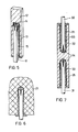
- Fig. 5 Krafteinleitungselement für einen Stab mit quadratischem Querschnitt;
- Fig. 6 Mauerwerksverankerung;
- Fig. 7 Verbindungselement für zwei Profile.
- 1 shows a force introduction element for a cylindrical rod;
- 2 shows a longitudinal section through a force application element according to FIG. 1;
- 3 shows a cross section through a force introduction element according to FIG. 1;
- Fig. 4 expansion element;
- Fig. 5 force introduction element for a rod with a square cross-section;
- Fig. 6 masonry anchorage;
- Fig. 7 connecting element for two profiles.
Der Stab 1 aus einem unidirektional verstärkten Faserverbündwerkstoff steckt in einer Ankerhülse 2, in der der Stab verankert ist und über die die Kräfte in bekannter Weise weitergeleitet werden können. Die Ankerhülse 2 ist axial aufgebohrt und mit einem Gewinde 3 versehen. Das Ende des Stabes 1 ist mit einem Kreuznagel 4 aufgeweitet. Der gesamte verbleibende freie Raum im Inneren der Ankerhülse ist lückenlos mit einer Vergußmasse 5 gefüllt.The
Die Bezugszeichen in Fig. 2 und 3 sind die gleichen wie in Fig. 1.The reference numerals in FIGS. 2 and 3 are the same as in FIG. 1.
Fig. 4 zeigt ein geeignetes Aufweitungselement.Fig. 4 shows a suitable expansion element.
Bei einem rechteckigen oder quadratischen Profil des Faserverbundwerkstoffs 11, wie in Fig. 5, ist es zweckmäßig, eine entsprechend eckig ausgebildete Ankerhülse 12 einzusetzen. Auch hier muß eine Profilierung 13 senkrecht zur Stabrichtung 11 vorhanden sein und das Stabende mit einem entsprechenden Aufweitungselement 14 versehen und alle verbleibenden Hohlräume vollständig mit Vergußmasse 15 ausgefüllt sein.In the case of a rectangular or square profile of the
In Fig. 6 ist eine Mauerwerksverankerung dargestellt. Dabei kann unter Umständen auf eine metallische Ankerhülse verzichtet werden. Eine ausreichende Profilierung der Bohrung kann beispielsweise durch Bohren in ausgehärteten Beton 20 oder durch Eingießen von Kernen, die nach Aushärtung des Betons wieder entfernt werden, hergestellt werden. In Fig. 7 ist dargestellt wie Profile miteinander verbunden werden können. Die beiden Stäbe 30,31 stecken in einer Ankerhülse 32, die von beiden Seiten her aufgebohrt und innenprofiliert 33 ist. Die Stabenden sind aufgeweitet 34 und eingegossen 35. Die Mehrfachverankerungen dienen zur Verbindung mehrere Profile mit fluchtenden und/oder senkrecht zueinander stehenden Profilachsen.In Fig. 6 a masonry anchor is shown. Under certain circumstances, a metallic anchor sleeve can be dispensed with. Adequate profiling of the bore can be produced, for example, by drilling into hardened concrete 20 or by pouring cores, which are removed again after the concrete has hardened. FIG. 7 shows how profiles can be connected to one another. The two
Ein Faserverbundwerkstoffstab auf Basis eines ungesättigten Polyesterharzes und ca. 83 Gew.-% undirektional orientierter Glasfasern, der einen runden Querschnitt mit einem Durchmesser von 8 mm hatte, wurde an beiden Enden ca. 1 cm tief kreuzförmig eingeschnitten und Kreuznägel gemäß Fig. 4 von 35 mm Länge und einem Kreuzdurchmesser von 6 mm mit der Spitze soweit in das Profil eingedrückt, daß sie durch die elastische Klemmkraft des Profilsegmentes fixiert wurden.A fiber composite rod based on an unsaturated polyester resin and approx. 83% by weight of non-directionally oriented glass fibers, which had a round cross section with a diameter of 8 mm, was cut approximately 1 cm deep in a cross shape at both ends and cross nails according to FIG. 4 of 35 mm length and a cross diameter of 6 mm with the tip pressed so far into the profile that they were fixed by the elastic clamping force of the profile segment.
Die Ankerhülsen bestanden aus dem Werkstoff St 52, hatten einen Außendurchmesser von 25 mm, waren 80 mm lang und wurden mit einer durchgehenden Bohrung, in der M 14-Gewinde geschnitten waren, versehen.The anchor sleeves were made of St 52 material, had an outer diameter of 25 mm, were 80 mm long and were provided with a through hole in which M 14 threads were cut.
Die Hülsen wurden einseitig temporär verschlossen und zu ca. 3/4 ihrer Länge mit einem füllstoff-freien kalthärtenden Epoxidharz gefüllt und die Profilenden mit den Kreuznägeln fest hineingedrückt, so daß das Harz alle Zwischenräume zwischen den Gewindebohrungen, den Stabsegmenten und den Kreuznägeln vollständig ausfüllte. Die so hergestellten Verankerungen versagten im Zugversuch bei einer Belastung von 65 300 N.The sleeves were temporarily closed on one side and filled to about 3/4 of their length with a filler-free cold-curing epoxy resin and the profile ends were pressed in firmly with the cross nails so that the resin completely filled all the spaces between the threaded holes, the rod segments and the cross nails. The anchorages thus produced failed in the tensile test at a load of 65,300 N.
Ein Faserverbundwerkstoffstab mit 8 mm 0 und verankert gemäß Beispiel 1, der drei Monate lang dem Einfluß natürlicher Wirkung unter einer Belastung von 42 000 N ausgesetzt wurde, erreichte im anschließenden Zugversuch eine Bruchkraft von 66 100 N.A fiber composite rod with 8 mm 0 and anchored according to Example 1, the influence of natural effects under a load of 42,000 N for three months was subjected to a breaking force of 66 100 N in the subsequent tensile test.
Ein Rundstab mit einem Durchmesser von 7,5 mm aus einem Faserverbundwerkstoff auf Basis eines ungesättigten Polyesterharzes und ca. 80 Gew.-% unidirektional orientierter Glasfasern wurde an beiden Ende ca. 1 cm tief kreuzförmig eingeschnitten und Kreuznägel, wie in Fig. 4 dargestellt, von 35 mm Länge und einem Kreuzdurchmesser von 6 mm wurden mit der Spitze soweit in das Profil eingedrückt, daß sie durch die elastische Klemmkraft der Profilsegmente fixiert wurden. Die Ankerhülsebestand aus dem Werkstoff St 52 und hatte einen Außendurchmesser von 20 mm. In die Sacklochbohrung von 65 mm Tiefe wurde ein M 12-Gewinde geschnitten. In das Sackloch wurden etwa 50 g einer schnell härtenden Vergußmasse eingefüllt und das Profilende mit dem Kreuznagel fest hineingedrückt. Die Vergußmasse bestand aus 20 Gew.-Teilen eines ungesättigten Polyesterharzes und je 40 Gew.-Teilen Quarzsand (1 mm Korndurchmesser) und Quarzmehl (Korndurchmesser = 200um). Die Vergußmasse füllte alle Zwischenräume zwischen der Gewindebohrung, dem Stab und den Kreuznägeln vollständig aus. So hergestellte Krafteinleitungselemente versagten im Zugversuch bei einer Belastung von 58 600 N.A round rod with a diameter of 7.5 mm made of a fiber composite material based on an unsaturated polyester resin and approx. 80% by weight of unidirectionally oriented glass fibers was cut in a cruciform shape at both ends by approx. 35 mm in length and a cross diameter of 6 mm were pressed into the profile with the tip to such an extent that they were fixed by the elastic clamping force of the profile segments. The anchor sleeve stock was made of St 52 material and had an outer diameter of 20 mm. An
Claims (7)
Applications Claiming Priority (2)
| Application Number | Priority Date | Filing Date | Title |
|---|---|---|---|
| DE3118492 | 1981-05-09 | ||
| DE3118492A DE3118492A1 (en) | 1981-05-09 | 1981-05-09 | FORCE INITIAL ELEMENT FOR FIBER COMPOSITES |
Publications (3)
| Publication Number | Publication Date |
|---|---|
| EP0064652A2 true EP0064652A2 (en) | 1982-11-17 |
| EP0064652A3 EP0064652A3 (en) | 1985-12-27 |
| EP0064652B1 EP0064652B1 (en) | 1988-09-14 |
Family
ID=6131919
Family Applications (1)
| Application Number | Title | Priority Date | Filing Date |
|---|---|---|---|
| EP82103491A Expired EP0064652B1 (en) | 1981-05-09 | 1982-04-24 | Anchoring element for fibre-compound materials |
Country Status (3)
| Country | Link |
|---|---|
| US (1) | US4526492A (en) |
| EP (1) | EP0064652B1 (en) |
| DE (2) | DE3118492A1 (en) |
Cited By (1)
| Publication number | Priority date | Publication date | Assignee | Title |
|---|---|---|---|---|
| DE3707292A1 (en) * | 1987-03-06 | 1988-09-15 | Korte Jungermann Hans Werner | Process for anchoring an anchor bolt |
Families Citing this family (6)
| Publication number | Priority date | Publication date | Assignee | Title |
|---|---|---|---|---|
| GB2364756B8 (en) * | 2000-07-14 | 2017-06-14 | Vitec Group Plc | Improvements in or relating to methods of forming joints between elongate members and sockets |
| DE10232762A1 (en) * | 2002-07-18 | 2004-02-12 | Kew Kunststofferzeugnisse Gmbh Wilthen | Fastening compound for fixing a fastening element and method |
| DE102007011987A1 (en) * | 2007-03-09 | 2008-09-18 | Technische Universität Chemnitz | Tension rod system for building and hall girder, has metal casings connected with tension rod in force fit, form fit and material fit manner, where metal casings exhibit fire-retardant enclosure including internal teeth |
| US11391312B2 (en) * | 2012-06-19 | 2022-07-19 | Megalex Joint, Llc | Method for creating a high tensile strength joint for connecting rods and fittings |
| US10132343B2 (en) * | 2012-06-19 | 2018-11-20 | Megalex Joint, Llc | High tensile strength joint for connecting rods and fittings |
| HU231446B1 (en) * | 2020-08-26 | 2023-11-28 | Pauger Kft. | Method for fixing end-terminal and splitting device |
Citations (4)
| Publication number | Priority date | Publication date | Assignee | Title |
|---|---|---|---|---|
| FR2138796A1 (en) * | 1971-05-20 | 1973-01-05 | Celmac Ag | |
| FR2234480A1 (en) * | 1973-06-22 | 1975-01-17 | Ici Ltd | |
| EP0014426A1 (en) * | 1979-01-31 | 1980-08-20 | GEBIRGSSICHERUNG Ges.m.b.H. | Rock anchor |
| US4247224A (en) * | 1978-12-14 | 1981-01-27 | Ppg Industries, Inc. | Method for installing a mine roof bolt |
Family Cites Families (11)
| Publication number | Priority date | Publication date | Assignee | Title |
|---|---|---|---|---|
| US87778A (en) * | 1869-03-16 | of titusville | ||
| US52793A (en) * | 1866-02-20 | Improved pipe-coupling | ||
| US90935A (en) * | 1869-06-08 | Improved coupling for pump-rods | ||
| US974719A (en) * | 1910-03-30 | 1910-11-01 | Charles Stevenson | Wire cable, socket, and coupling. |
| US1381779A (en) * | 1919-09-25 | 1921-06-14 | Thomas M Williams | Dead-end clamp for cables |
| US2426920A (en) * | 1942-08-20 | 1947-09-02 | Wilhelm B Bronander | Method of forming and applying cooling fins to tubular members |
| US2874937A (en) * | 1955-11-25 | 1959-02-24 | Edward F Higgins | Corrosion-resistant sucker rod and method of constructing same |
| US3129282A (en) * | 1962-08-23 | 1964-04-14 | Anderson Electric Corp | Strain insulators |
| US3328229A (en) * | 1963-11-06 | 1967-06-27 | Dow Chemical Co | Method and apparatus for attaching load bearing members to low strength bodies |
| US3552787A (en) * | 1968-10-28 | 1971-01-05 | Alfred A Yee | Wire cage-type splice sleeve for reinforcing bars |
| GB1524469A (en) * | 1976-08-13 | 1978-09-13 | Ici Ltd | Dowel device for grouting in a drillhole |
-
1981
- 1981-05-09 DE DE3118492A patent/DE3118492A1/en not_active Withdrawn
-
1982
- 1982-04-22 US US06/371,028 patent/US4526492A/en not_active Expired - Fee Related
- 1982-04-24 EP EP82103491A patent/EP0064652B1/en not_active Expired
- 1982-04-24 DE DE8282103491T patent/DE3279034D1/en not_active Expired
Patent Citations (4)
| Publication number | Priority date | Publication date | Assignee | Title |
|---|---|---|---|---|
| FR2138796A1 (en) * | 1971-05-20 | 1973-01-05 | Celmac Ag | |
| FR2234480A1 (en) * | 1973-06-22 | 1975-01-17 | Ici Ltd | |
| US4247224A (en) * | 1978-12-14 | 1981-01-27 | Ppg Industries, Inc. | Method for installing a mine roof bolt |
| EP0014426A1 (en) * | 1979-01-31 | 1980-08-20 | GEBIRGSSICHERUNG Ges.m.b.H. | Rock anchor |
Cited By (1)
| Publication number | Priority date | Publication date | Assignee | Title |
|---|---|---|---|---|
| DE3707292A1 (en) * | 1987-03-06 | 1988-09-15 | Korte Jungermann Hans Werner | Process for anchoring an anchor bolt |
Also Published As
| Publication number | Publication date |
|---|---|
| EP0064652B1 (en) | 1988-09-14 |
| DE3279034D1 (en) | 1988-10-20 |
| EP0064652A3 (en) | 1985-12-27 |
| DE3118492A1 (en) | 1982-12-02 |
| US4526492A (en) | 1985-07-02 |
Similar Documents
| Publication | Publication Date | Title |
|---|---|---|
| EP2817465B1 (en) | Device for the application of force to tension members from fiber-reinforced plastic plates | |
| EP2606185B1 (en) | Device for introducing a force into tension members made of fiber-reinforced plastic flat strip lamella | |
| WO2014154207A1 (en) | Structural arrangement and method for securing scaffolding to a building wall | |
| EP0064652B1 (en) | Anchoring element for fibre-compound materials | |
| EP1397601B1 (en) | Shear connector | |
| EP1259679B1 (en) | Anchoring for a pre-tensioned and/or loaded strength member and anchor sleeve | |
| EP0188174A1 (en) | Anchor for wall consolidation in cavity structures | |
| DE102007057291A1 (en) | Edge connection producing method for precast concrete walls in e.g. industrial building construction, involves tightening clamp bolt and reinforcement plate in such manner that concrete walls are connected by pre-stressing | |
| EP0319736B1 (en) | Method of fixing anchoring bolts in concrete and compounds mass | |
| EP0015895A1 (en) | Tension bolt for anchoring construction elements in a foundation body | |
| DE102009022828B4 (en) | Trussed girder including an underframe and a related method of manufacture | |
| WO2005035892A1 (en) | Device comprising a rod made of fiber-reinforced plastic for transferring a load through a heat-insulating layer | |
| EP2977528B1 (en) | Reinforcement assembly for a structure and method of reinforcing a structure having such a reinforcement assembly | |
| EP0739442B1 (en) | Tensionable gfp rock anchor | |
| WO1999004116A1 (en) | Component | |
| DE19958375A1 (en) | System for transferring force, especially in aircraft construction, consists of tubes connected by coaxial sleeve, first tube being glued to sleeve and gap between second tube and sleeve containing pressure medium | |
| EP3135861B1 (en) | Attachment device | |
| WO2015197441A1 (en) | Anchor dowel | |
| EP3578832B1 (en) | Method for assembling a screw for porous concrete, use and assembly | |
| EP0697530A1 (en) | Anchoring bolt for concrete or similar | |
| DE7630026U1 (en) | CONNECTOR AND SEALING DEVICE FOR REPAIRING UNWANTED CAVITIES IN PREFERRED MASONRY OR CONCRETE | |
| DE3631653C1 (en) | Anchorage for a rock bolt | |
| DE3124544A1 (en) | Sleeve for sheathing bars, reinforced-concrete piles or the like | |
| EP3757404A1 (en) | Insulating body for a fixing device for fastening an object without heat bridges to a substrate having an insulating layer, and fixing device comprising such an insulating body | |
| AT514173A1 (en) | Structure |
Legal Events
| Date | Code | Title | Description |
|---|---|---|---|
| PUAI | Public reference made under article 153(3) epc to a published international application that has entered the european phase |
Free format text: ORIGINAL CODE: 0009012 |
|
| 17P | Request for examination filed |
Effective date: 19820424 |
|
| AK | Designated contracting states |
Designated state(s): BE CH DE FR GB IT NL |
|
| PUAL | Search report despatched |
Free format text: ORIGINAL CODE: 0009013 |
|
| AK | Designated contracting states |
Designated state(s): BE CH DE FR GB IT LI NL |
|
| 17Q | First examination report despatched |
Effective date: 19870311 |
|
| R17C | First examination report despatched (corrected) |
Effective date: 19870527 |
|
| GRAA | (expected) grant |
Free format text: ORIGINAL CODE: 0009210 |
|
| ITF | It: translation for a ep patent filed |
Owner name: SOCIETA' ITALIANA BREVETTI S.P.A. |
|
| AK | Designated contracting states |
Kind code of ref document: B1 Designated state(s): BE CH DE FR GB IT LI NL |
|
| REF | Corresponds to: |
Ref document number: 3279034 Country of ref document: DE Date of ref document: 19881020 |
|
| ET | Fr: translation filed | ||
| GBT | Gb: translation of ep patent filed (gb section 77(6)(a)/1977) | ||
| PLBE | No opposition filed within time limit |
Free format text: ORIGINAL CODE: 0009261 |
|
| STAA | Information on the status of an ep patent application or granted ep patent |
Free format text: STATUS: NO OPPOSITION FILED WITHIN TIME LIMIT |
|
| 26N | No opposition filed | ||
| PGFP | Annual fee paid to national office [announced via postgrant information from national office to epo] |
Ref country code: DE Payment date: 19930317 Year of fee payment: 12 |
|
| PGFP | Annual fee paid to national office [announced via postgrant information from national office to epo] |
Ref country code: GB Payment date: 19930419 Year of fee payment: 12 |
|
| PGFP | Annual fee paid to national office [announced via postgrant information from national office to epo] |
Ref country code: BE Payment date: 19930427 Year of fee payment: 12 |
|
| PGFP | Annual fee paid to national office [announced via postgrant information from national office to epo] |
Ref country code: FR Payment date: 19930428 Year of fee payment: 12 |
|
| ITTA | It: last paid annual fee | ||
| PGFP | Annual fee paid to national office [announced via postgrant information from national office to epo] |
Ref country code: NL Payment date: 19930430 Year of fee payment: 12 Ref country code: CH Payment date: 19930430 Year of fee payment: 12 |
|
| PG25 | Lapsed in a contracting state [announced via postgrant information from national office to epo] |
Ref country code: GB Effective date: 19940424 |
|
| PG25 | Lapsed in a contracting state [announced via postgrant information from national office to epo] |
Ref country code: LI Effective date: 19940430 Ref country code: CH Effective date: 19940430 Ref country code: BE Effective date: 19940430 |
|
| BERE | Be: lapsed |
Owner name: BAYER A.G. Effective date: 19940430 |
|
| PG25 | Lapsed in a contracting state [announced via postgrant information from national office to epo] |
Ref country code: NL Effective date: 19941101 |
|
| NLV4 | Nl: lapsed or anulled due to non-payment of the annual fee | ||
| GBPC | Gb: european patent ceased through non-payment of renewal fee |
Effective date: 19940424 |
|
| PG25 | Lapsed in a contracting state [announced via postgrant information from national office to epo] |
Ref country code: FR Effective date: 19941229 |
|
| REG | Reference to a national code |
Ref country code: CH Ref legal event code: PL |
|
| PG25 | Lapsed in a contracting state [announced via postgrant information from national office to epo] |
Ref country code: DE Effective date: 19950103 |
|
| REG | Reference to a national code |
Ref country code: FR Ref legal event code: ST |