EP0064576A1 - Transmission à courroie dentée et procédé pour la production d'une telle courroie - Google Patents
Transmission à courroie dentée et procédé pour la production d'une telle courroie Download PDFInfo
- Publication number
- EP0064576A1 EP0064576A1 EP81302003A EP81302003A EP0064576A1 EP 0064576 A1 EP0064576 A1 EP 0064576A1 EP 81302003 A EP81302003 A EP 81302003A EP 81302003 A EP81302003 A EP 81302003A EP 0064576 A1 EP0064576 A1 EP 0064576A1
- Authority
- EP
- European Patent Office
- Prior art keywords
- belt
- pulley
- teeth
- discontinuities
- surface discontinuities
- Prior art date
- Legal status (The legal status is an assumption and is not a legal conclusion. Google has not performed a legal analysis and makes no representation as to the accuracy of the status listed.)
- Granted
Links
Images


Classifications
-
- F—MECHANICAL ENGINEERING; LIGHTING; HEATING; WEAPONS; BLASTING
- F16—ENGINEERING ELEMENTS AND UNITS; GENERAL MEASURES FOR PRODUCING AND MAINTAINING EFFECTIVE FUNCTIONING OF MACHINES OR INSTALLATIONS; THERMAL INSULATION IN GENERAL
- F16H—GEARING
- F16H55/00—Elements with teeth or friction surfaces for conveying motion; Worms, pulleys or sheaves for gearing mechanisms
- F16H55/02—Toothed members; Worms
- F16H55/17—Toothed wheels
- F16H55/171—Toothed belt pulleys
-
- B—PERFORMING OPERATIONS; TRANSPORTING
- B29—WORKING OF PLASTICS; WORKING OF SUBSTANCES IN A PLASTIC STATE IN GENERAL
- B29D—PRODUCING PARTICULAR ARTICLES FROM PLASTICS OR FROM SUBSTANCES IN A PLASTIC STATE
- B29D29/00—Producing belts or bands
- B29D29/08—Toothed driving belts
-
- F—MECHANICAL ENGINEERING; LIGHTING; HEATING; WEAPONS; BLASTING
- F16—ENGINEERING ELEMENTS AND UNITS; GENERAL MEASURES FOR PRODUCING AND MAINTAINING EFFECTIVE FUNCTIONING OF MACHINES OR INSTALLATIONS; THERMAL INSULATION IN GENERAL
- F16G—BELTS, CABLES, OR ROPES, PREDOMINANTLY USED FOR DRIVING PURPOSES; CHAINS; FITTINGS PREDOMINANTLY USED THEREFOR
- F16G1/00—Driving-belts
- F16G1/28—Driving-belts with a contact surface of special shape, e.g. toothed
-
- F—MECHANICAL ENGINEERING; LIGHTING; HEATING; WEAPONS; BLASTING
- F16—ENGINEERING ELEMENTS AND UNITS; GENERAL MEASURES FOR PRODUCING AND MAINTAINING EFFECTIVE FUNCTIONING OF MACHINES OR INSTALLATIONS; THERMAL INSULATION IN GENERAL
- F16H—GEARING
- F16H7/00—Gearings for conveying rotary motion by endless flexible members
- F16H7/02—Gearings for conveying rotary motion by endless flexible members with belts; with V-belts
- F16H7/023—Gearings for conveying rotary motion by endless flexible members with belts; with V-belts with belts having a toothed contact surface or regularly spaced bosses or hollows for slipless or nearly slipless meshing with complementary profiled contact surface of a pulley
Definitions
- This invention relates to positive drive power transmission systems composed of toothed belts in combination with toothed pulleys and methods for making such toothed belts. More particularly, the invention is directed to positive drive power transmission systems in which the operating noise resulting from the impact of the toothed belts against their corresponding toothed pulleys is reduced substantially.
- U.S. Patent No. 2,507,852 issued on May 16, 1952 to R. Y. Case, describes in detail a power transmission belt comprising an inextensible tensile member having teeth bonded to it on one side.
- a protective jacket fabric covers the teeth.
- the teeth are made of an elastomeric material, such as rubber.
- the belt is designed to mesh with one or more toothed pulleys that are constructed of material having a higher Young's modulus than the elastomeric material of the belt teeth.
- Such toothed belts have been constructed with teeth of various cross-sectional configurations.
- the tooth cross-sectional configuration shown in the Case patent is trapezoidal, similar to that of a conventional rack gear tooth.
- U.S. Patent No. 3,756,091, issued on September 4, 1973 to H. F. Miller describes in detail a similar power transmission belt where the tooth cross-sectional configuration is substantially curvilinear being partially composed of two intersecting arcs.
- Different tooth cross-sectional configurations have been described in patents such as U.S. Patent No. 3,924,481, issued on December 9, 1975 to M.J.W. Gregg; U.S. Patent No. 4,037,485, issued July 26, 1977 to R.D. Hoback; U.S. Patent No.
- Toothed power transmission belts having cross-sectional configurations as described in the patents to Case and Miller, as well as belts having teeth of other configurations, are used throughout industry.
- the characteristic sound of such a positive drive power transmission system in operation is a loud "whine".
- the whine is comprised primarily of the meshing frequency of the system i.e. the frequency of collisions or impact contacts between the toothed belt and its pulleys and the integer harmonics of the meshing frequency.
- the meshing frequency is calculated by multiplying the number of grooves in the pulley by the pulley's speed of rotation. For example, a belt running on a 30-groove pulley turning at 40 revolutions per second would generate a noise composed of a 1200 Hz fundamental frequency and its integer harmonics, i.e. 2400 Hz, 3600 Hz, etc.
- noise levels in excess of 80dB normally result. It is not uncommon for noise to be generated in excess of 90dB.
- Noise reduction is achieved by the placing of surface discontinuities on the belt, the pulley, or both wherever noise generating impact contact takes place between the belt and the pulleys. These discontinuities act to modify the impact contact between the belt and pulley and thus reduce the resulting noise.
- the term "surface discontinuities” means a series of raised or recessed portions on the working surface of the belt or pulley.
- the surface discontinuities can be uniform or non-uniform in shape and distributions. They may be straight or curved. They may have any vertical and horizontal cross-sectional contours or combinations of contours. They may be continuous or discontinuous or any combination thereof.
- the dimensions of individual elements forming the surface discontinuities may be equal or unequal in height, depth, width or diameter.
- the surface discontinuities may be regularly or randomly spaced across the width of the belt or pulley.
- noise generating impact contact takes place where the pulley teeth engage and compress the flank of the belt tooth and the belt land area.
- noise generating impact contact occurs where the belt teeth tips compressively engage the bottoms of the pulley cavities or grooves.
- the surface discontinuities must be placed where impact contact takes place.
- the surface discontinuities may be at different locations.
- the surface discontinuities may be positioned over all areas where contact may possibly take place, i.e. over the entire working surface of the belt or pulley. Methods of manufacturing belts with such surface discontinuities are also disclosed.
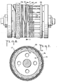
- a positive drive power transmission system is shown composed of an endless toothed belt 10 and two toothed pulleys 11 and 12.
- the belt 10 transmits power from the driving pulley 11 to the driven pulley 12.
- the belt 10 is provided with a tensile member 13 formed from a plurality of turns of a continuous strand of filamentary material.
- the tensile member 13 carries substantially the entire working load imposed upon the belt 10.
- the pulleys 11 and 12 have teeth 14 made of relatively rigid material, such as metal or hard plastic.
- the belt 10 has teeth 15 made of somewhat yieldable resilient elastomer or plastic material which is sufficiently firm to substantially maintain its shape under the load imposed on it.
- Figs. 2 and 3 illustrate belts 10 having teeth with different cross-sectional configurations, i.e. trapezoidal and curvilinear, respectively.
- the belt shown in Fig. 2 is of the type disclosed in the Case patent and the belt shown in Fig. 3 is of the type disclosed in the Miller patent.
- Belts with these cross-sectional configurations, as well as belts with other cross-sectional configurations such as those previously described, are commonly used to form one of the components of positive drive power transmission systems.
- the belts 10 shown in Figs. 2 and 3 have their teeth 15 on one side of the belt. Teeth may, however, be positioned on two or more sides of the belt 10. The teeth on different sides of the belt need not have the same cross-sectional configurations.
- the Case and Miller patents may be consulted for a more detailed description of their respective positive drive power transmission systems.
- Figs. 14, 16 and 17 disclose belts in accordance with the present invention having teeth with trapezoidal cross-sectional configurations in accordance with the Case patent and Figs. 4, 5 and 15 disclose belts with teeth having curvilinear cross-sectional configurations in accordance with the Miller patent.
- the present invention is equally applicable to these belts as well as belts having teeth with different cross-sectional configurations such as those disclosed in the Gregg, Hoback, Redmond and Gregg et. al. patents.
- the positive drive belt 10 has teeth 15 bonded to the body 16 of the belt.
- the tensile member 13 is embedded in the body 16.
- the inner or working surface of the belt can be divided into three areas: teeth flanks 17, teeth tips 18 and land surfaces 19 between adjacent teeth 15.
- Each pulley 11 and 12 is composed of a body portion 40 with teeth 14 formed thereon.
- the outer or working surface of the pulley 11 and 12 is composed of two areas: pulley teeth tips 33 and the pulley cavities or grooves 34.
- the pulley cavities or grooves 34 may be considered to have flank portions and land portions separating the flank portions of adjacent teeth.
- any toothed positive drive power transmission system produces a noise when working surfaces of the the belt and pulleys collide or have impact contact with each other as they work.
- the level of the noise depends on a number of parameters including tension, horsepower, torque and speed of operation.
- the sound is characteristically that of a whine comprised primarily of the meshing frequency and its integer harmonics.
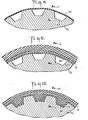
- Figs. 4, 5 show a belt 10 in accordance with the teachings of the Miller patent having the preferred embodiment of surface discontinuities formed on its working surface. While the surface discontinuities are shown on a belt having teeth with a curvilinear configuration, the invention works with the teeth of other cross-sectional configurations.
- the surface discontinuities of this embodiment are in the form of longitudinal ridges 21 spaced transversely across the entire working surface of the belt 10, i.e. teeth flanks 17, teeth tips 18 and land surfaces 19.
- the ridges 21 extend parallel to each other in the longitudinal operating direction of the belt. As shown there are seven ridges 21. There may, however, be more or less than this number.
- Figs. 6-14 illustrate the method of placing ridges of one preferred embodiment of surface discontinuities on a trapezoidal tocthed belt.
- the elements of the belt 10 are built upon a mold 22 having axially extending trapezoidal grooves 23 which grooves constitute molds for the formation of the belt teeth 15.
- extensible thread 24 is spirally wound around the mold 22.
- the thread is made from a material, such as a cured rubber which is treated or selected so as not to bond to the belt 10 during its vulcanization.
- a series of spaced bands may be used.
- the cross-sectional configuration of the thread 24 may be square, rectangular, circular, trapezoidal or any other suitable configuration, as will become readily apparent hereinafter.
- the dimensions of the thread cross-section will control the height, the shape of the flanks and the width of the space between the surface discontinuities.
- the spacing of the thread winding will control the width of the surface discontinuities.
- one or more layers of stretchable fabric 25 is then applied around the mold 22 over the thread 24.
- the tensile member 13 is then spirally wound around the fabric 25.
- An elastomer layer 26 is positioned around the tensile member 13.
- a curing bag or wrap 27 for applying pressure to the belt parts 13, and 24-26 is positioned around the elastomer layer 26. The entire assembly is heated and pressure is applied to curing bag or wrap 27 to force. the elastomer 26 between spaces in the tension member 13 as shown in Figs. 9 and 10 to form and vulcanize the belt 10. See the Skura patent for details of the molding and curing process.
- the thread 24 may be substantially inextensible and frangible. The force and pressure exerted would then cause the portion of the thread between the raised ribs on the mold to break. Thus, the thread would result only in creating surface discontinuities on portions of the belt teeth flanks 17 and the land surfaces 19.
- an inextensible thread may be applied over the surface of the grooved mold by use of adherents or by preforming the required contours in a rigid thread.
- surface discontinuity dimensions length, width, height, and spacing
- the selection of surface discontinuity dimensions will be influenced by the size of the teeth of the belt as well as by the compressibility of the surface discontinuities in relation to the loads to be encountered by the belt. Larger surface discontinuities having dimensions such as 1 . 27 mm for height, width, and spacing, were found useful in the large pitch belt such as 14mm belts while smaller dimensions such as 0.7 6 mm were advantageous in the smaller belts such as one-half inch pitch belts.
- Belt tooth sizes and pitches cover a wide range for applications from fractional horsepower to hundreds of horsepower. Experiments have shown that the most useful range of dimensions for the surface discontinuities lies between 0.4 and 3 . 18 mm
- Figs. 15, 16 & 17 show alternate embodiments of belt 10 having surface discontinuites in accordance with the present invention.
- surface discontinuities are discontinuous across the surface of the belt and extend less than the distance between adjacent teeth.
- the belt 10 is of the type disclosed in the Miller patent.
- noise generating impact contact occurs in the area of the juncture of the belt teeth flanks 17 and the belt land areas 19.
- the surface discontinuities 40 may accordingly be placed only in this impact contact area, i.e. on the land areas 19 and teeth flanks 17 of the belt tooth, but need not be placed on the teeth tips 18. Alternatively, they may be placed over the entire working surface of the belt 10. If impact contact occured only in the belt tooth tip area, the surface discontinuities could be confined to that area.
- a belt 10 has the surface discontinuities 29 in the form of circular raised portions, equally recessed portions may be used. These surface discontinuities 29 are shown as cylindrical. As noted previously alternate shapes, such as hemispherical protuberances, may be used.
- the raised portions may be in a random or uniform pattern but arranged such that one-quarter to three-quarters of the impact contact area is raised. The surface discontinuities may be confined to the impact contact area or cover the entire working surface of the belt 10.
- Fig. 17 discloses a belt having teeth where the surface discontinuities are on the entire working surface 17, 18 and 19 of the belt 10.
- the surface discontinuities are a plurality of parallel, uniformly spaced discontinuous ridge-like projections 30 placed in a "herringbone” or zig-zag pattern.
- the surface discontinuities may be oriented at any angle to the tensile member, including perpendicular to the operating directions of the belt.
- Figs. 15, 16 and 17 disclose just some of the possible shapes of the surface discontinuities which discontinuities may be positioned over the entire working surface of the belt or be confined to the impact contact area.
- Belts such as shown in these figures may be manufactured by the same method as that of the , preferred embodiment except that instead of winding thread 24 around the mold 22, a sheet 31 of cured extensible material with holes, cavities, or raised portions corresponding to the desired surface discontinuities positioned thereon.
- the material forming sheet 31 is selected or is treated so as not to bond to the belt 10 during its vulcanization.
- Such a sheet 31 is being shown removed from the belt of Fig. 16 after vulcanization of the belt.
- the sheet 31 may be formed from an inextensible frangible material which is positioned around the mold 22 but not in the mold grooves 23. The sheet 31 will break during molding, creating surface discontinuities on only a portion of the belt 10.
- an inextensible sheet may be positioned around the mold 22 and in grooves 23 by means of an adherent or by pre-shaping of the sheet 31 to the contours of the mold 22.
- the mold 22 can be made with surface discontinuities formed in its surface. This may require that the mold 22 be collapsible radially inwardly for belt slab removal. This latter method would however eliminate the need for use of a thread 24, or sheet 31. ⁇
- the surface discontinuity can be provided through the use of a jacket fabric 25 having surface discontinuities formed therein.
- the jacket must be of such a tight weave, or precoated, to prevent rubber strike-through during the belt curing process.
- the surface of the jacket 25 which would face the mold would be of such a material as would not flatten out during the belt fabrication and curing process.
- the surface discontinuities could be obtained by a pronounced weave in the jacket fabric 25, and by the application of a high-melting or non- thermoplastic material attached to the fabric by molding or by other means.
- the fabric 25 may be extensible or inextensible depending on its method of application.
- the belt 10 can be manufactured by methods other than that shown in the Skura patent, such as by step cures in which belt materials are progressively advanced between flat molding plates or by continuous molding techniques where the belt elements are advanced between a heated grooved cylindrical mold and a pressure band. Using such systems, the surface discontinuities can be formed directly in the mold surfaces. Finally a belt 10 in accordance with the present invention can be made by using substantially liquid elastomer introduced into a cavity between a mold and an external cylinder. The mold could be prepared with thread 24 or sheet 31 as previously discussed.
- Figs. 18 and 19 show a pulley 11 having surface discontinuities in the pulley teeth tips 32 in the form of parallel serrations 33.
- the cross sectional configuration of the surface discontinuities is shown as semi-circular. Alternate cross sectional contours can also produce noise reduction.
- the surface discontinuities may be regularly or randomly spaced. They may be positioned at an angle to the pulley. If the area of impact contact between the belt and pulleys occur in the pulley cavities or grooves 34, the surface discontinuities should be located in this area. Alternatively the entire working surface, i.e. tooth tips 32 and cavities 34, could have surface discontinuities thereon.
- Figs. 20 through 33 are graphs of test results showing noise produced by positive drive power transmission systems with and without surface discontinuities. These and similar tests have shown that surface discontinuities with dimensions between
- dB decible
- the decible (dB) scale has been adopted internationally for use with sound level metering testing.
- the dB ratings are sometimes weighted to correspond with the subjective response of the ear.
- the weighted dB readings are known as dB(A).
- the overall dB(A) value was recorded and is plotted on each graph above the notation "A".
- a 1/3-octave spectrum analyzer was used to evaluate the unweighted values at the frequencies making up the sound produced by the belt and pulley.
- the spectrum analyzer divides the range of frequencies audible to humans into 30 bands, each designated by its center frequency such as 2,000, 2,500, 3,150, 4,000 Hz, etc. If a sound has a particularly high component around 3,000 Hz, it will be indicated as a high reading of the 3,125 Hz center-frequency band.
- Figs. 20 through 31 utilize jacketed 14 mm pitch belts with 100 curvilinear teeth having cross-sectional configurations in accordance with the Miller patent. Each belt was 40mm wide. The running condition was selected to produce a noise level such as encountered in normal operation of such positive drive power transmission systems. The tests were run at 1875 RPM using 32-groove pulleys to produce a meshing frequency of belt tooth with pulley groove of 1000 impact contacts per second.
- This frequency is shown as F 1 on the horizontal axis -of each graph, and F Z , F3 and F4 represent the integer harmonic center-frequency values of 2000, 3125, and 4000 Hz.
- the lower noise levels observed at intermediate frequencies between F 1 , F 2 , F 31 and F 4 are omitted from the graphs for easier interpretation.
- Fig. 20 the results are shown of running the positive drive power transmission system without surface discontinuities.
- the system had an overall noise reading of 93dB(A) and a range of 78 to 90 dB for the meshing frequency and its harmonics.
- Figs. 21 through 29 surface discontinuities of the type shown in the preferred embodiment manufactured by the preferred method were used.
- Precured rubber threads of various sizes were wound on the mold surface at various turns-per-cm of application, the resulting ridges had specific dimensions of height, spacing between adjacent ridges, and width, so that the effect of such dimensions on noise could be demonstrated.
- Fig. 23 80 dB(A) and 68 dB at F 3 .
- the belt of Fig. 22 which showed the lowest noise level had 50 percent of its area composed of the raised discontinuities.
- Fig. 21 was 67 percent raised and Fig. 23 was 33 percent raised.
- Figs. 24, 25 and 26 smaller 1.07mm square cross-section cured rubber thread was used at 20.32, 30.48 and 40.64 turns-per-cm, producing surface discontinuities having height and spacing of 1 .02 mm, widths of 2.03 mm , 1.02 mm , and 0.51 mm and raised portions covering 67, 50, and 33 percent of the area respectively.
- the noise levels were all lower than that using the plain belt of Fig. 20 but not quite as effective as the discontinuities of Fig. 22.
- Figs. 27, 28, and 29 utilized an even finer 0 . 84 mm square cross-section cured rubber thread applied at 20.32, 30. 48 and 40.64 turns /cm to provide surface discontinuities having height and spacing of 0..76 mm and widths of 2.39 mm 1.27 mm , and 0. 7 6 cm ; and covering 73, 60 and 40 percent of the area respectively.
- noise levels were reduced from those of the plain belt of Fig. 20, but not to the extent experienced in Fig. 22.
- noise levels are reduced by the presence of the surface discontinuities on not only the belt alone, or the pulley alone, but when situated on both the belt and pulley.
Priority Applications (2)
| Application Number | Priority Date | Filing Date | Title |
|---|---|---|---|
| EP19810302003 EP0064576B1 (fr) | 1981-05-07 | 1981-05-07 | Transmission à courroie dentée et procédé pour la production d'une telle courroie |
| DE8181302003T DE3172811D1 (en) | 1981-05-07 | 1981-05-07 | Positive drive power transmission system, belts and pulleys therefor, and method of making such belts |
Applications Claiming Priority (1)
| Application Number | Priority Date | Filing Date | Title |
|---|---|---|---|
| EP19810302003 EP0064576B1 (fr) | 1981-05-07 | 1981-05-07 | Transmission à courroie dentée et procédé pour la production d'une telle courroie |
Publications (2)
| Publication Number | Publication Date |
|---|---|
| EP0064576A1 true EP0064576A1 (fr) | 1982-11-17 |
| EP0064576B1 EP0064576B1 (fr) | 1985-11-06 |
Family
ID=8188293
Family Applications (1)
| Application Number | Title | Priority Date | Filing Date |
|---|---|---|---|
| EP19810302003 Expired EP0064576B1 (fr) | 1981-05-07 | 1981-05-07 | Transmission à courroie dentée et procédé pour la production d'une telle courroie |
Country Status (2)
| Country | Link |
|---|---|
| EP (1) | EP0064576B1 (fr) |
| DE (1) | DE3172811D1 (fr) |
Cited By (4)
| Publication number | Priority date | Publication date | Assignee | Title |
|---|---|---|---|---|
| WO1998007561A1 (fr) * | 1996-08-22 | 1998-02-26 | The Goodyear Tire And Rubber Company | Procede et dispositif de production de courroies synchrones comportant au moins deux voies de crantage helicoidales |
| EP0928908A1 (fr) * | 1998-01-12 | 1999-07-14 | ContiTech Antriebssysteme GmbH | Roue utilisée dans un entraínement à courroie et entraínement à courroie |
| WO2007120417A1 (fr) * | 2006-03-29 | 2007-10-25 | The Gates Corporation | Roue dentee de courroie synchrone |
| WO2012099604A1 (fr) * | 2011-01-21 | 2012-07-26 | Otis Elevator Company | Système et procédé pour réduire un bruit de courroie |
Families Citing this family (2)
| Publication number | Priority date | Publication date | Assignee | Title |
|---|---|---|---|---|
| DE19908672C1 (de) * | 1999-02-26 | 2001-02-15 | Peter Baeumler | Zahnriementriebelement |
| DE102004055127A1 (de) * | 2004-11-16 | 2006-06-29 | Volkswagen Ag | Zahnriemen |
Citations (12)
| Publication number | Priority date | Publication date | Assignee | Title |
|---|---|---|---|---|
| GB189514849A (en) * | 1895-08-06 | 1895-10-12 | Henry Harris Lake | Improvements in Pulleys. |
| US1959972A (en) * | 1931-08-27 | 1934-05-22 | Wanamaker Ernest | Pulley |
| FR1210936A (fr) * | 1958-03-24 | 1960-03-11 | Goodyear Tire & Rubber | Procédé et appareillage pour la fabrication de courroies et courroies en résultant |
| US3404576A (en) * | 1965-11-12 | 1968-10-08 | Pirelli | Belt and gear drive |
| US3464875A (en) * | 1966-08-26 | 1969-09-02 | Dayco Corp | Method of making endless v-type transmission belts having inwardly disposed transverse teeth |
| DE2115843A1 (de) * | 1971-04-01 | 1972-10-12 | Wandrey, Karl, Dipl Ing , 7157Murrhardt | Riemenscheibe fur gerauscharmen Betrieb |
| DE2333006A1 (de) * | 1972-08-21 | 1974-03-07 | Uniroyal Inc | Endloser treibriemen fuer riementriebe |
| US4037485A (en) * | 1975-12-18 | 1977-07-26 | The Goodyear Tire & Rubber Company | Belt drive and belts and pulleys therefor |
| US4066732A (en) * | 1976-11-19 | 1978-01-03 | The Gates Rubber Company | Toothed belt making |
| GB1497422A (en) * | 1974-04-26 | 1978-01-12 | Pirelli | Manufacture of toothed belts |
| GB1570714A (en) * | 1975-12-18 | 1980-07-09 | Goodyear Tire & Rubber | Beltd drive including toothed bels and toothed pulleys of tooth configurations |
| DE3009468A1 (de) * | 1979-03-16 | 1980-09-25 | Pirelli | Zahnriemen |
-
1981
- 1981-05-07 DE DE8181302003T patent/DE3172811D1/de not_active Expired
- 1981-05-07 EP EP19810302003 patent/EP0064576B1/fr not_active Expired
Patent Citations (13)
| Publication number | Priority date | Publication date | Assignee | Title |
|---|---|---|---|---|
| GB189514849A (en) * | 1895-08-06 | 1895-10-12 | Henry Harris Lake | Improvements in Pulleys. |
| US1959972A (en) * | 1931-08-27 | 1934-05-22 | Wanamaker Ernest | Pulley |
| FR1210936A (fr) * | 1958-03-24 | 1960-03-11 | Goodyear Tire & Rubber | Procédé et appareillage pour la fabrication de courroies et courroies en résultant |
| US3404576A (en) * | 1965-11-12 | 1968-10-08 | Pirelli | Belt and gear drive |
| GB1143269A (en) * | 1965-11-12 | 1969-02-19 | Pirelli | A belt and gear drive |
| US3464875A (en) * | 1966-08-26 | 1969-09-02 | Dayco Corp | Method of making endless v-type transmission belts having inwardly disposed transverse teeth |
| DE2115843A1 (de) * | 1971-04-01 | 1972-10-12 | Wandrey, Karl, Dipl Ing , 7157Murrhardt | Riemenscheibe fur gerauscharmen Betrieb |
| DE2333006A1 (de) * | 1972-08-21 | 1974-03-07 | Uniroyal Inc | Endloser treibriemen fuer riementriebe |
| GB1497422A (en) * | 1974-04-26 | 1978-01-12 | Pirelli | Manufacture of toothed belts |
| US4037485A (en) * | 1975-12-18 | 1977-07-26 | The Goodyear Tire & Rubber Company | Belt drive and belts and pulleys therefor |
| GB1570714A (en) * | 1975-12-18 | 1980-07-09 | Goodyear Tire & Rubber | Beltd drive including toothed bels and toothed pulleys of tooth configurations |
| US4066732A (en) * | 1976-11-19 | 1978-01-03 | The Gates Rubber Company | Toothed belt making |
| DE3009468A1 (de) * | 1979-03-16 | 1980-09-25 | Pirelli | Zahnriemen |
Cited By (10)
| Publication number | Priority date | Publication date | Assignee | Title |
|---|---|---|---|---|
| WO1998007561A1 (fr) * | 1996-08-22 | 1998-02-26 | The Goodyear Tire And Rubber Company | Procede et dispositif de production de courroies synchrones comportant au moins deux voies de crantage helicoidales |
| US6183582B1 (en) | 1996-08-22 | 2001-02-06 | The Goodyear Tire & Rubber Company | Method and apparatus for producing synchronous belts with two or more tracks of helical teeth |
| EP0928908A1 (fr) * | 1998-01-12 | 1999-07-14 | ContiTech Antriebssysteme GmbH | Roue utilisée dans un entraínement à courroie et entraínement à courroie |
| WO2007120417A1 (fr) * | 2006-03-29 | 2007-10-25 | The Gates Corporation | Roue dentee de courroie synchrone |
| WO2012099604A1 (fr) * | 2011-01-21 | 2012-07-26 | Otis Elevator Company | Système et procédé pour réduire un bruit de courroie |
| CN103328368A (zh) * | 2011-01-21 | 2013-09-25 | 奥的斯电梯公司 | 用于减少带的噪声的系统和方法 |
| RU2596043C2 (ru) * | 2011-01-21 | 2016-08-27 | Отис Элевэйтор Компани | Система и способ уменьшения шума от ремня |
| CN103328368B (zh) * | 2011-01-21 | 2016-09-28 | 奥的斯电梯公司 | 用于减少带的噪声的系统和方法 |
| RU2596043C9 (ru) * | 2011-01-21 | 2016-12-20 | Отис Элевэйтор Компани | Система и способ уменьшения шума от ремня |
| US10336581B2 (en) | 2011-01-21 | 2019-07-02 | Otis Elevator Company | System and method for reducing belt noise |
Also Published As
| Publication number | Publication date |
|---|---|
| DE3172811D1 (en) | 1985-12-12 |
| EP0064576B1 (fr) | 1985-11-06 |
Similar Documents
| Publication | Publication Date | Title |
|---|---|---|
| US4416649A (en) | Reduced noise positive drive power transmission system | |
| US2507852A (en) | Transmission belt and drive | |
| EP0588971B1 (fr) | Structure de courroie | |
| EP0010919B1 (fr) | Courroie de transmission sans fin | |
| DE2660998C2 (fr) | ||
| US4514179A (en) | Power transmission belt with fabric cover | |
| US4512834A (en) | Method of making reduced noise positive drive power transmission system | |
| US4392842A (en) | Toothed positive drive power transmission belt with a fabric reinforcement suspended within the belt teeth | |
| US4011766A (en) | Endless power transmission belt | |
| US4177688A (en) | Endless power transmission belt and method for making same | |
| US4305714A (en) | Heavy duty laminated cogged belt | |
| US2941413A (en) | Power transmission belts | |
| DE112013003955T5 (de) | Zahnriemen und diesen umfassendes Riemenuntersetzungsgetriebe | |
| EP0064576B1 (fr) | Transmission à courroie dentée et procédé pour la production d'une telle courroie | |
| US5382198A (en) | Helically grooved multi-ribbed power transmission belt | |
| JPS63246532A (ja) | 伝動ベルト | |
| AU672258B2 (en) | Belt, belt/pulley combination and method of making | |
| US4884998A (en) | Endless power transmission belt construction and method of making the same | |
| US4976662A (en) | Endless power transmission belt construction and method of making the same | |
| US4617075A (en) | Method of making a belt | |
| US4931118A (en) | Method of manufacturing multiribbed belts | |
| US20030017901A1 (en) | Reduced noise multi-ribbed power transmission belt | |
| JPH0115736B2 (fr) | ||
| KR850000353B1 (ko) | 저소음 적극구동 전동장치 | |
| US4722721A (en) | Synchronous drive system and method of making the same |
Legal Events
| Date | Code | Title | Description |
|---|---|---|---|
| PUAI | Public reference made under article 153(3) epc to a published international application that has entered the european phase |
Free format text: ORIGINAL CODE: 0009012 |
|
| AK | Designated contracting states |
Designated state(s): DE FR GB IT |
|
| 17P | Request for examination filed |
Effective date: 19830428 |
|
| ITF | It: translation for a ep patent filed |
Owner name: DE DOMINICIS & MAYER S.R.L. |
|
| GRAA | (expected) grant |
Free format text: ORIGINAL CODE: 0009210 |
|
| AK | Designated contracting states |
Designated state(s): DE FR GB IT |
|
| REF | Corresponds to: |
Ref document number: 3172811 Country of ref document: DE Date of ref document: 19851212 |
|
| ET | Fr: translation filed | ||
| PLBE | No opposition filed within time limit |
Free format text: ORIGINAL CODE: 0009261 |
|
| STAA | Information on the status of an ep patent application or granted ep patent |
Free format text: STATUS: NO OPPOSITION FILED WITHIN TIME LIMIT |
|
| 26N | No opposition filed | ||
| PGFP | Annual fee paid to national office [announced via postgrant information from national office to epo] |
Ref country code: GB Payment date: 19900427 Year of fee payment: 10 |
|
| PGFP | Annual fee paid to national office [announced via postgrant information from national office to epo] |
Ref country code: FR Payment date: 19900510 Year of fee payment: 10 |
|
| ITTA | It: last paid annual fee | ||
| PGFP | Annual fee paid to national office [announced via postgrant information from national office to epo] |
Ref country code: DE Payment date: 19900629 Year of fee payment: 10 |
|
| PG25 | Lapsed in a contracting state [announced via postgrant information from national office to epo] |
Ref country code: GB Effective date: 19910507 |
|
| GBPC | Gb: european patent ceased through non-payment of renewal fee | ||
| PG25 | Lapsed in a contracting state [announced via postgrant information from national office to epo] |
Ref country code: FR Effective date: 19920131 |
|
| PG25 | Lapsed in a contracting state [announced via postgrant information from national office to epo] |
Ref country code: DE Effective date: 19920303 |
|
| REG | Reference to a national code |
Ref country code: FR Ref legal event code: ST |