EP0064567B1 - Car loader with hydraulically tiltable tailboard - Google Patents
Car loader with hydraulically tiltable tailboard Download PDFInfo
- Publication number
- EP0064567B1 EP0064567B1 EP81103544A EP81103544A EP0064567B1 EP 0064567 B1 EP0064567 B1 EP 0064567B1 EP 81103544 A EP81103544 A EP 81103544A EP 81103544 A EP81103544 A EP 81103544A EP 0064567 B1 EP0064567 B1 EP 0064567B1
- Authority
- EP
- European Patent Office
- Prior art keywords
- rear wall
- lever
- driver
- frame
- pressure cylinder
- Prior art date
- Legal status (The legal status is an assumption and is not a legal conclusion. Google has not performed a legal analysis and makes no representation as to the accuracy of the status listed.)
- Expired
Links
Images


Classifications
-
- B—PERFORMING OPERATIONS; TRANSPORTING
- B60—VEHICLES IN GENERAL
- B60P—VEHICLES ADAPTED FOR LOAD TRANSPORTATION OR TO TRANSPORT, TO CARRY, OR TO COMPRISE SPECIAL LOADS OR OBJECTS
- B60P1/00—Vehicles predominantly for transporting loads and modified to facilitate loading, consolidating the load, or unloading
- B60P1/04—Vehicles predominantly for transporting loads and modified to facilitate loading, consolidating the load, or unloading with a tipping movement of load-transporting element
- B60P1/26—Means for controlling movement of tailboards or sideboards
-
- A—HUMAN NECESSITIES
- A01—AGRICULTURE; FORESTRY; ANIMAL HUSBANDRY; HUNTING; TRAPPING; FISHING
- A01D—HARVESTING; MOWING
- A01D90/00—Vehicles for carrying harvested crops with means for selfloading or unloading
- A01D90/10—Unloading means
Landscapes
- Engineering & Computer Science (AREA)
- Life Sciences & Earth Sciences (AREA)
- Environmental Sciences (AREA)
- Transportation (AREA)
- Mechanical Engineering (AREA)
- Agricultural Machines (AREA)
- Types And Forms Of Lifts (AREA)
- Shovels (AREA)
Abstract
Description
Die Erfindung betrifft einen Ladewagen mit einem Roll- oder Kratzboden, einen über einem festen Aufbau angeordneten erhöhbaren Aufbau, sowie einer am Entladeende mittels mindestens eines einseitig am festen Aufbau angelenkten Druckzylinders über einen Aushebemechanismus ausschwenkbare Rückwand, die über eine Drehachse am freien Ende eines am festen Aufbau schwenkbar angelenkten Bügels, der in seiner untersten Stellung eine etwa horizontale Lage einnimmt, schwenkbar angelenkt ist und über wenigstens einen federbelasteten Riegel am festen Aufbau verriegelbar ist.The invention relates to a loading wagon with a rolling or scraper floor, a height-adjustable structure arranged above a fixed structure, and a rear wall which can be pivoted out at the unloading end by means of at least one pressure cylinder articulated on one side on the fixed structure via a lifting mechanism and which has an axis of rotation at the free end of a fixed structure Structure pivotally hinged bracket, which occupies an approximately horizontal position in its lowest position, is pivotally hinged and can be locked to the fixed structure via at least one spring-loaded latch.
Zweck der Verschwenkung der Rückwand eines Ladewagens mittels Druckzylindern ist es, Erleichterungen für die Bedienungsperson zu schaffen, welche somit vom Schleppersitz aus und ohne Kraftaufwand das Schwenken der Rückwand vornehmen kann.The purpose of pivoting the rear wall of a loading wagon by means of pressure cylinders is to make it easier for the operator, who can thus pivot the rear wall from the tractor seat and without effort.
Aus dem DE-U- 6929397 ist eine Ausführung bekannt, wobei eine Rückwand frei pendelnd an einem schwenkbeweglichen Hebelarm angelenkt ist. Das Ausschwenken der Rückwand wird hier ebenfalls mittels eines Hydraulikzylinders vorgenommen, wobei der Hydraulikzylinder über einen Seilzug den schwenkbeweglichen Hebelarm nach oben verschwenkt und somit die am Hebelarm angelenkte Rückwand mit hochzieht. Auf dem ersten Verschwenkweg des Hydraulikzylinders wird ein federbelasteter Riegel angehoben, womit die Rückwand nach hinten auspendeln kann. Die ausgependelte Stellung ist dabei die Stellung zum «Grünfutterentladen».From DE-U- 6929397 an embodiment is known, wherein a rear wall is freely pivoted on a pivotable lever arm. The swiveling out of the rear wall is also carried out here by means of a hydraulic cylinder, the hydraulic cylinder swiveling the pivoting lever arm upwards by means of a cable pull and thus pulling up the rear wall hinged to the lever arm. A spring-loaded latch is raised on the first swivel path of the hydraulic cylinder, allowing the rear wall to swing backwards. The balanced position is the position for «unloading green fodder».
Nachteilig bei der genannten Anordnung ist das umständliche Wiedereinrasten der Rückwand wobei mehrere Bremsmanöver erforderlich sein können, bis die Rückwand wieder in Verriegelungsstellung kommt. Beim Abbremsen aus höherer Geschwindigkeit kann zwar sicher eingerastet werden, jedoch gehen die dabei entstehenden Schläge auf die Verriegelungseinrichtung zu Lasten der Standzeit dieser Elemente, wobei Beschädigungen nicht ausgeschlossen sind. Durch die nicht sehr weite Auspendelung der Rückwand in «Grünfutterentladestellung» kann es zu Behinderungen durch das querstehende Rahmenteil der Rückwand kommen. Beim Verschwenken des Hebels zum Erreichen der Dürrfutter-Entladestellung, schwenkt die Rückwand infolge der Veränderung ihrer Schwerpunktlage in Bezug auf ihre Schwenkachse in ihre Ausgangslage zurück, bis sie am Hebel zum Anliegen kommt. Durch das Zurückschwenken der Rückwand ist ein unbehindertes Entladen nicht möglich, da ein Teil der benötigten Entladefläche durch die Rückwand abgedeckt wird.A disadvantage of the arrangement mentioned is the cumbersome re-engagement of the rear wall, and several braking maneuvers may be required until the rear wall comes back into the locking position. When braking from a higher speed, it can be securely engaged, but the resulting blows on the locking device are detrimental to the service life of these elements, and damage is not excluded. Due to the not very wide swinging out of the rear wall in “green fodder unloading position”, the transverse frame part of the rear wall can cause disabilities. When the lever is pivoted to reach the dry forage unloading position, the rear wall swivels back into its starting position as a result of the change in its center of gravity with respect to its pivot axis until it comes to rest on the lever. Unwindered unloading is not possible by swiveling back the rear wall, since part of the required unloading area is covered by the rear wall.
Einstellbare Zwischenstellungen der Rückwand im Grünfutterbereich sind in der gezeigten Anordnung nicht möglich.Adjustable intermediate positions of the rear wall in the green forage area are not possible in the arrangement shown.
Weiterhin ist eine Ausführung aus dem DE-U-6601 710 bekannt, wobei eine mittels Hydraulikzylinder hochklappbare Rückwand verwendet wird. Der Ladewagen weist im gezeigten Beispiel zwar einen Aufbau für Dürrfutter bzw. für Heu auf, jedoch ist dieser nicht klappbar ausgebildet. Für niedere Stallungen bzw. niedere Stalleinfahrten kann man, beim Grünfuttereinbringen, wobei das Ladegut bis zur Oberkante der festen Seitenwände geladen wird, auf einen abklappbaren bzw. abnehmbaren Dürrfutteraufbau, welcher hierbei nicht benötigt wird, nicht verzichten. Geht man von der Annahme aus, dass im gezeigten Beispiel der Dürrfutteraufbau abnehmbar ausgebildet ist, so ist diese Anordnung dennoch für das Entladen von Grünfutter in niederen Stallungen ungeeignet, da die hochschwenkbare Rückwand bereits in geschlossener Stellung über die Oberkante der festen Seitenwände hinwegragt, wobei beim Ausheben der Rückwand die obere Kante der Rückwand die Oberkante der festen Seitenwände noch weiter überragt.Furthermore, an embodiment is known from DE-U-6601 710, wherein a rear wall which can be folded up by means of a hydraulic cylinder is used. In the example shown, the loading wagon has a structure for dry forage or for hay, but it is not designed to be foldable. For low stables or low barn entrances, when introducing green fodder, the load being loaded up to the upper edge of the fixed side walls, one cannot do without a foldable or removable dry forage construction, which is not required here. Assuming that in the example shown the dry forage structure is removable, this arrangement is still unsuitable for unloading green fodder in low stables, since the swiveling rear wall already protrudes above the upper edge of the fixed side walls in the closed position, with the Lifting out the rear wall, the upper edge of the rear wall extends beyond the upper edge of the fixed side walls.
Der Erfindung liegt nunmehr die Aufgabe zugrunde, die genannten Nachteile zu vermeiden und eine vom Schleppersitz aus bedienbare Rückwand derart auszubilden, wobei ein problemloses Entladen von Grünfutter in niederen Stallungen ermöglicht wird, sowie ein ungehinderter Durchgang beim Dürrfutterentladen gewährleistet ist.The invention is based on the object of avoiding the disadvantages mentioned and of designing a rear wall which can be operated from the tractor seat in such a way that problem-free unloading of green fodder in low-sized stables is made possible and unhindered passage during unloading of dry fodder is ensured.
Diese Aufgabe wird gemäss der Erfindung dadurch gelöst, dass ein Aushebemechanismus der ausschwenkbaren Rückwand aus einem mit radialem Abstand zu der Schwenkachse der Rückwand drehbar gelagerten Hebel gebildet wird, dessen freies Ende durch den am festen Aufbau angelenkten Druckzylinder beaufschlagt wird und einen Mitnehmer, der in den Schwenkbereich der Rückwand bringbar ist, aufweist, sowie aus einer am Hebel angelenkten und zum Riegel geführten Entriegelungseinrichtung und einem weiteren, in den Schwenkbereich des Bügels bringbaren Mitnehmer.This object is achieved according to the invention in that a lifting mechanism of the swing-out rear wall is formed from a lever which is rotatably mounted at a radial distance from the pivot axis of the rear wall, the free end of which is acted upon by the pressure cylinder articulated on the fixed structure and a driver which moves into the The rear wall can be pivoted, has an unlocking device that is articulated on the lever and leads to the bolt, and a further driver that can be brought into the pivoting region of the bracket.
Vorteilhafterweise wird vorgeschlagen, den Mitnehmer für den Bügel durch eine Anschlagfläche am Hebel oder durch einen an der beweglichen Rückwand angebrachten Anschlag, welcher bei einem bestimmten Verschwenkwinkel der Rückwand auf dem Bügel aufsitzt, auszubilden.It is advantageously proposed to design the driver for the bracket by means of a stop surface on the lever or by means of a stop attached to the movable rear wall, which is seated on the bracket at a certain pivoting angle of the rear wall.
Um ein sicheres Verriegeln der Rückwand zu gewährleisten ist es vorteilhaft zwischen dem Bügel und der Rückwand eine Zugfeder anzubringen, welche entgegen Kraftrichtung des Druckzylinders wirkt, womit das Einrasten des Riegels gewährleistet wird.In order to ensure a secure locking of the rear wall, it is advantageous to install a tension spring between the bracket and the rear wall, which acts counter to the direction of force of the pressure cylinder, thus ensuring that the latch is locked into place.
In einer weiteren Ausgestaltung der Erfindung wird vorgeschlagen, den Anlenkpunkt des Druckzylinders am festen Aufbau, bezogen auf die Fahrtrichtung, hinter und unterhalb der Schwenkachse des Bügels anzubringen und den Anlenkpunkt des Hebles derart zuzuordnen, dass der lotrechte Abstand "L" der Wirkungslinie "W" des Druckzylinders zur Schwenkachse des Bügels in unterster Stellung der Rückwand annähernd "Null" beträgt und mit dem Anheben anwächst. Dadurch wird sichergestellt, dass bis zum Erreichen der «Grünfutterstellung» der Rückwand, keine nach oben gerichtete Kraftkomponente auftritt, welche ein unbeabsichtigtes Anheben des Bügels hervorruft.In a further embodiment of the invention it is proposed to attach the articulation point of the pressure cylinder to the fixed structure, relative to the direction of travel, behind and below the pivot axis of the bracket and to assign the articulation point of the lever in such a way that the vertical distance "L" corresponds to the line of action "W" of the pressure cylinder to the swivel axis of the bracket in the lowest position of the rear wall is approximately "zero" and increases with lifting. This ensures that there is no upward force component until the “green fodder position” of the rear wall is reached occurs, which causes an unintentional lifting of the bracket.
Um ein folgerichtiges Anheben des Bügels erst nach Erreichen der Grünfutterentlade-Stellung der Rückwand zu gewährleisten wird vorgeschlagen, dass der Mitnehmer für den Bügel erst bei der genannten Stellung wirksam wird.In order to ensure a consequent lifting of the bracket only after the green forage unloading position of the rear wall has been reached, it is proposed that the driver for the bracket only become effective in the position mentioned.
In einer weiteren Ausgestaltung der Erfindung wird vorgeschlagen, dass beim Verschwenken des Hebles aus der Verriegelungsstellung auf seinem ersten Schwenkweg, bevor der Mitnehmer für die Rückwand zum Anliegen kommt, die Entriegelungseinrichtung für den Riegel betätigt.In a further embodiment of the invention it is proposed that when the lever is pivoted out of the locking position on its first pivoting path before the driver for the rear wall comes to rest, the unlocking device for the bolt is actuated.
Um ein Verwinden der Rückwand beim Ausheben zu vermeiden und somit Beschädigungen auszuschliessen, wird weiter vorgeschlagen den Aushebemechanismus sowie die Verriegelungseinheit beidseitig des Ladewagens anzubringen.In order to avoid twisting of the rear wall when lifting out and thus to prevent damage, it is further proposed to attach the lifting mechanism and the locking unit on both sides of the loading wagon.
Vorteilhafterweise wird weiter vorgeschlagen in den Aushebemechanismus Schaltelemente einzubauen, welche steuernd in den Stromkreis eingreifen, über welchen ein Wegeventil beaufschlagt wird, das einen Druckzylinder zum Ausheben der Rückwand ansteuert.Advantageously, it is further proposed to install switching elements in the lifting mechanism, which control elements in the circuit, via which a directional valve is actuated, which controls a pressure cylinder for lifting the rear wall.
Das absatzweise Anheben der Rückwand bzw. des Bügels bringt den Vorteil mit sich, dass beim Grünfutterladen nur ein Teil der hinteren Verschlusswand angehoben werden muss, womit der Energiebedarf zum Anheben auf ein Minimum gesenkt wird, im Gegensatz zu einstückigen Verschlusswänden.The incremental lifting of the rear wall or bracket has the advantage that only a part of the rear closing wall has to be raised when loading green forage, which means that the energy required for lifting is reduced to a minimum, in contrast to one-piece closing walls.
Ein Ausführungsbeispiel der Erfindung wird in den nachfolgenden Zeichnungen dargestellt und im folgenden näher beschrieben.An embodiment of the invention is shown in the following drawings and described in more detail below.
Es zeigen:
- Fig. 1: Eine erfindungsgemässe Rückwand eines Ladewagens in Verriegelungsstellung in Seitenansicht gesehen.
- Fig. 2: Eine Rückwand nach Fig. 1 in ausgehobener «Grünfutterentladestellung».
- Fig. 3: Eine Rückwand nach Fig. 1 in ausgehobener «Dürrfutterentladestellung».
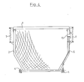
- Fig. 4: Eine Rückwand nach Fig. 1 in Hinteransicht.
- Fig. 5: Schematisch einen Stromversorgungs-und Funktionsplan zur Ausführungsform nach Fig. 1 bis 4.
- Fig. 1: An inventive rear wall of a loading wagon seen in the locked position in side view.
- Fig. 2: A rear wall according to Fig. 1 in the raised "green fodder unloading position".
- Fig. 3: A rear wall according to Fig. 1 in the raised "dry forage unloading position".
- Fig. 4: A rear wall of FIG. 1 in a rear view.
- 5: Schematic of a power supply and functional diagram for the embodiment according to FIGS. 1 to 4.
Figur 1 zeigt eine Teilansicht eines Ladewagens. Über einem nicht näher dargestellten Kratzboden sind feste Seitenwände A angebracht. Im oberen Bereich der festen Seitenwände A ist ein klappbarer Aufbau B angelenkt. Ebenfalls im oberen Bereich der festen Seitenwand ist in der Drehachse 1a ein etwa horizontal ausgerichteter Bügel 1 angelenkt, welcher eine Schwenkachse 2a aufweist, in welcher eine Rückwand 2 schwenkbar gelagert ist. Die Rückwand 2 nimmt dabei in der gezeigten Stellung eine etwa vertikale Verriegelungsstellung ein.Figure 1 shows a partial view of a loading wagon. Fixed side walls A are attached above a scraper floor, not shown. A foldable structure B is articulated in the upper region of the fixed side walls A. Also in the upper region of the fixed side wall, an approximately horizontally
Über einen Riegel 4 der einen am festen Aufbau angebrachten Bolzen 9 übergreift und um die Achse 4a an der Rückwand 2 schwenkbar gelagert ist, wird die Rückwand 2 mit dem festen Aufbau A verriegelt.The
Ein Seilzug 6, welcher an der Rückwand 2 geführt wird, ist einenends mit dem freien Ende des Riegels 4 verbunden und anderenends an einem an der Rückwand 2 um eine Schwenkachse 3a drehbar gelagerten Hebel 3. Der Seilzug ist dabei an einem Bolzen 14 des Hebels 3 befestigt, an welchem ebenfalls eine Zugfeder 8 angreift, die an der Rückwand 2 angelenkt ist. Durch die Zugfeder 8 resultiert eine Kraft, welche den Hebel 3 nach vorne drückt.A
Ein einfach wirkender Hydraulikzylinder 5 ist am festen Aufbau A über die Achse 5a und am Hebel 3 über die Achse 5b angelenkt.A single-acting
Der Hebel 3 weist einen Mitnehmer 10 auf, der in den Schwenkbereich des Bügels 1 geführt werden kann. Ausserdem weist der Hebel im Bereich der Achse 5b des Hydraulikzylinders einen Mitnehmer 11 auf, der in den Schwenkbereich der Rückwand 2 ragt. Zwischen dem Bügel 1 und der Rückwand 2 ist eine Zugfeder 7 angebracht, welche entgegen der Wirkungslinie "W" des Hydraulikzylinders 5 gerichtet ist. Die gestrichelte Darstellung des Riegels 4 in Figur 1 zeigt ihn in der Verriegelungsstellung, wobei sich der Hydraulikzylinder in seiner eingefahrenen Stellung befindet und der Mitnehmer 11 noch nicht an der Rückwand 2 anliegt. Zwischen dem rückwärtigen Teil des Bügels 1 und der Rückwand 2 ist eine rucksackartige Netzbespannung D angebracht. Von der äusseren Begrenzung des freien Schenkels des Bügels 1 und über den höchsten Punkt des klappbaren Aufbaus B sind Seile C gespannt, welche eine obere flexible Begrenzung des Laderaumes für Dürrfutter darstellen.The
Der Funktionsablauf des Aushebemechanismus der Rückwand 2 ist wie folgt:
- Der
Hydraulykzylinder 5, welcher über eineDruckleitung 12 mit Druckmittel beaufschlagt wird, schwenkt denHebel 3 um die Schwenkachse 3a. Auf seinem ersten Schwenkwinkel a, wo derMitnehmer 11 noch nicht wirksam ist, wird lediglich derSeilzug 6 angezogen, womit der Riegel 4, entgegen einerDrehfeder 13, angehoben wird und somit dieRückwand 2 freigibt. Bei weiterem Ausfahren desHydraulikzylinders 5 wird, infolge des Auftreffens desMitnehmers 11 auf dieRückwand 2, dieRückwand 2 um die Schwenkachse 2a nach oben verschwenkt bis die Anschlagfläche desMitnehmers 10 amBügel 1 ansteht. Diese Stellung, inFigur 2 dargestellt; reicht aus, um Grünfutter, welches bis zurOberkante 0 des festen Aufbaues A geladen werden kann, problemlos zu entladen. Um vor Erreichen der «Grünfutter-Entladestellung» (Fig.2) derRückwand 2 ein vorzeitiges Anheben desBügels 1 infolge eines Drehmomentes durch die Kraftrichtung des Druckzylinders in Bezug auf die Drehachse 1a zu verhindern, sind die Anlenkpunkte derart angeordnet, dass der Hebelarm "L" bis zum Erreichen der genannten Stellung relativ klein gehalten wird und erst beim Überschreiten dieser Stellung mehr anwächst.
- The
hydraulic cylinder 5, which is supplied with pressure medium via apressure line 12, pivots thelever 3 about the pivot axis 3a. At its first swivel angle a, where thedriver 11 is not yet effective, only thecable 6 is tightened, with which the bolt 4 is raised, counter to atorsion spring 13, and thus releases therear wall 2. When thehydraulic cylinder 5 is extended further, therear wall 2 is pivoted upward about the pivot axis 2a as a result of the impact of thedriver 11 on therear wall 2 until the stop surface of thedriver 10 abuts thebracket 1. This position, shown in Figure 2; is sufficient to unload green fodder, which can be loaded up to thetop edge 0 of the fixed structure A, without any problems. In order to prevent premature lifting of thebracket 1 as a result of a torque caused by the direction of force of the pressure cylinder with respect to the axis of rotation 1a before the “green forage unloading position” (FIG. 2) of therear wall 2, the articulation points are arranged in such a way that the lever arm " L "is kept relatively small until the said position is reached and only grows when this position is exceeded.
Ist die Rückwand 2 bis zur Entladung für Grünfutter angehoben, so liegt der Mitnehmer 1o auf dem Bügel 1 auf. Bei weiterer Beaufschlagung des Hydraulikzylinders 5 wird nun auch der Bügel 1 mit samt der Rückwand 2 bis in eine obere Stellung, wie in Figur 3 dargestellt, angehoben, in welcher der freie Durchgang zum Entladen von Dürrfutter, das in der Regel bis zur oberen Begrenzung eines klappbaren Aufbaues B geladen wird, gewährleistet ist. Die äussere Begrenzung der freien Schenkel der Rückwand 2 und des Bügels 1 befinden sich dabei etwa auf der Höhe der oberen Begrenzung des abklappbaren Aufbaues B.The back wall is 2 until the discharge for green forage raised, the driver 1o rests on the
Der Schliessvorgang der Rückwand 2 geht nun in umgekehrter Folge vor sich. Ein Steuerventil 16 des Hydraulikzylinders wird auf Senken gestellt. Infolge des Eigengewichtes des Bügels 1 und der Rückwand 2 wird der Druckzylinder 5, welcher nun nicht mehr mit Drucköl beaufschlagt ist, eingefahren. Der Bügel 1 kehrt in seine horizontale Lage zurück, bis er auf der Oberkante 0 aufliegt. Das weitere Schliessen der Rückwand besorgt die Zugfeder 7, die selbige in eine etwa vertikale Lage zurückbringt. Durch die Feder 8 wird nun der Hebel 3 in seine vorderste Ausgangsstellung zurückgezogen, womit der Seilzug 6 nachgeben kann und der Riegel 4 hinter dem Bolzen 9 einrastet.The closing process of the
Der Verriegelungs- und Aushebemechanismus kann auch beidseitig am Ladewagen angebracht sein.The locking and lifting mechanism can also be attached to the loading wagon on both sides.
In Figur 4 ist eine Rückansicht nach Figur 1 auf die Ladewagenrückwand gezeigt, bei welcher der Aushebemechanismus einseitig und die Zugfeder 7 zweiseitig angeordnet ist. Die Rückwand 2 befindet sich dabei in Verriegelungsstellung; auf die Darstellung des Fahrwerks und des klappbaren Aufbaues wurde hierbei verzichtet.FIG. 4 shows a rear view according to FIG. 1 of the loading wagon rear wall, in which the lifting mechanism is arranged on one side and the tension spring 7 is arranged on both sides. The
Figur 5 zeigt die Funktionssteuerung des Aushebemechanismusses. Dem Hebel 3 sind dabei zwei Endschalter g und d zugeordnet, welche beim Erreichen der Grünfutter- bzw. Dürrfutter- entladestellung (Fig. 2 und 3) unterbrechend in den Stromkreis einwirken können. Der einfachwirkende Hydraulikzylinder 5 wird dabei, ausgehend von einer Hydropumpe 15 über ein 3/3 Wegeventil und einem Drosselventil 17 angesteuert. Der Ölstrom wird somit im Vor- wie im Rücklauf gedrosselt, um ein zu schnelles Anheben und Senken zu vermeiden. In der Figur 5 ist das Wegeventil 16 in seiner durch die Federn F1 und F2 gehaltene Neutralstellung gezeigt, bei welcher der Füllzustand des Hydraulikzylinders aufrechterhalten und damit die Aushebehöhe der Rückwand fixiert ist, d. h. es kann jede beliebige Zwischenstellung der Rückwand eingestellt werden. Zwei elektromagnetische Ventilschalter 18 und 19 sind an Masse angeschlossen und haben je eine Speiseleitung 20 bzw. 20, 22 und 21. Je nach dem, welche der beiden Speiseleitungen an Potential gelegt sind, nimmt das Wegeventil die Stellung «Heben» bzs. «Senken» ein.FIG. 5 shows the function control of the lifting mechanism. The
Die Verbindung des Ventilschalter 18 mit der Stromquelle erfolgt nun über den vom Hebel 3 betätigbaren Schalter g und dem Handschalter 23 oder den vom Hebel 3 betätigbaren Schalter d und dem Handschalter 23, während die Verbindung des Ventilschalters 19 mit der Stromquelle nur über den Handschalter 23 erfolgt.The connection of the
In Ruhestellung sind die beiden Schalter d und g geschlossen.In the rest position, the two switches d and g are closed.
Der Handschalter 23 weist eine wirkungslose Schaltstellung "0" auf, die gerastet ist, sowie weitere gerastete Stellungen "G" und "D" in welchen der Hebekontakt mit der Speiseleitung 24 verbunden ist, sowie schliesslich eine getastete Schaltstellung S in der der Senkkontakt über die Speiseleitung 24 an die Stromquelle angeschlossen ist.The
Die Funktionsweise der elektrohydraulischen Steuerung erfolgt wie nachstehend beschrieben:The electrohydraulic control works as follows:
Wird der Handhebel des Handschalters 23, bei über den Zündkontakt geschlossenen Schalter 25, auf "G" eingerastet, was gleichbedeutend mit Grünfutter-Entladestellung ist, so wird der Elektromagnet 18 über den geschlossenen Schalter g angesteuert. Dadurch wird das Wegeventil 16 auf "H" gleich Heben verschoben, womit der Hydraulikzylinder mit Druckmittel über die hydraulische Leitung 12 beaufschlagt wird und ausfährt. Der Hebel 3 wird dadurch verschwenkt, womit der bereits beschriebene Aushebevorgang der Rückwand 2 vorgenommen wird, bis die Entladestellung für Grünfutter erreicht ist. Beim Erreichen dieser Stellung wird der Schalter "g" durch den Hebel 3 beaufschlagt, womit dieser öffnet und somit die Stromzufuhr zum Elektromagnet 18 unterbricht. Das Wegeventil wird durch die Feder F2 wieder in die Neutralstellung "N" zurückgebracht womit die Zufuhr von Druckmittel zum Hydraulikzylinder unterbrochen ist. Die Rückführung von Druckmittel vom Hydraulikzylinder ist gesperrt, so dass der Hydraulikzylinder bzw. die Rückwand in dieser Lage verbleibt.If the hand lever of the
Will man die Rückwand 2 wieder schliessen, so wird der Handschalter 23 auf "S" gleich Senken gestellt. Es erfolgt eine Beaufschlagung des Elektromagneten 19, welcher das Wegeventil 16 auf Senken S verschiebt, womit der Rückfluss des Druckmittels erfolgt und die Rückwand 2 infolge ihres Eigengewichtes unter Einwirkung der Federn 7 in ihrer Verriegelungsstellung zurückkehrt. Mit dem Absenken der Rückwand 2 wird der Hebel 3 ebenfalls wieder zurückgeschwenkt, womit der Schalter "g" wieder seine Schliesstellung einnimmt und somit ein erneuter «Hebe-Befehl» ausgeführt werden kann.If you want to close the
Will man die Dürrfutterentladestellung erreichen, so stellt man den Handhebel 23 auf D womit ebenfalls das Magnetventil 18 über die Leitungen 22 und 20 angesteuert wird und das Wegeventil 16 auf Heben "H" verschiebt. Der Hydraulikzylinder wird nun solange mit Druckmittel beaufschlagt bis die Stellung für Dürrfutterentladung Figur 3 erreicht ist, wobei der Schalter "d" durch den Hebel 3 geöffnet wird und somit die Stromzufuhr zum Elektromagnet 18 unterbricht. Durch die Feder F2 wird das Wegeventil wieder in Neutralstellung N gebracht, das den Rückfluss des Druckmittels verhindert und somit die angehobene Rückwand 2 und den Bügel 1 in ihrer obersten Lage hält. Das Schliessen der Rückwand auf dieser Stellung erfolgt gleich wie das Schliessen aus der Grünfutterentladestellung, indem der Handschalter 23 auf Senken "S" gestellt wird und somit der Rücklauf des Druckmittels durch Verschieben des Wegeventils, durch Beaufschlagung des Elektromagnetes 19 geöffnet ist.If you want to reach the dry forage unloading position, you set the
Vorteilhafterweise kann mit dieser Steuerung jede Zwischenstellung der Rückwand bzw. des Bügels eingestellt werden.Advantageously, any intermediate position of the rear wall or bracket can be set with this control.
Claims (9)
Priority Applications (3)
| Application Number | Priority Date | Filing Date | Title |
|---|---|---|---|
| EP81103544A EP0064567B1 (en) | 1981-05-09 | 1981-05-09 | Car loader with hydraulically tiltable tailboard |
| AT81103544T ATE8318T1 (en) | 1981-05-09 | 1981-05-09 | LOADER WAGON WITH HYDRAULICALLY SWINGING REAR PANEL. |
| DE8181103544T DE3164698D1 (en) | 1981-05-09 | 1981-05-09 | Car loader with hydraulically tiltable tailboard |
Applications Claiming Priority (1)
| Application Number | Priority Date | Filing Date | Title |
|---|---|---|---|
| EP81103544A EP0064567B1 (en) | 1981-05-09 | 1981-05-09 | Car loader with hydraulically tiltable tailboard |
Publications (2)
| Publication Number | Publication Date |
|---|---|
| EP0064567A1 EP0064567A1 (en) | 1982-11-17 |
| EP0064567B1 true EP0064567B1 (en) | 1984-07-11 |
Family
ID=8187706
Family Applications (1)
| Application Number | Title | Priority Date | Filing Date |
|---|---|---|---|
| EP81103544A Expired EP0064567B1 (en) | 1981-05-09 | 1981-05-09 | Car loader with hydraulically tiltable tailboard |
Country Status (3)
| Country | Link |
|---|---|
| EP (1) | EP0064567B1 (en) |
| AT (1) | ATE8318T1 (en) |
| DE (1) | DE3164698D1 (en) |
Families Citing this family (6)
| Publication number | Priority date | Publication date | Assignee | Title |
|---|---|---|---|---|
| GB2233938B (en) * | 1989-07-21 | 1993-10-27 | Glyndwr Shaw | Improvements in or relating to vehicle tail-gate latching mechanisms. |
| DE4205046A1 (en) * | 1992-02-19 | 1993-08-26 | Scheibenzuber Jun Josef | CLOSING MECHANISM |
| AT401135B (en) * | 1994-05-10 | 1996-06-25 | Bauer & Co Gmbh Reform Werke | Unloading device provided on a loader for cereal and/or leaf crops and metering device for the unloading material |
| DE29510800U1 (en) * | 1995-07-04 | 1996-10-31 | Kemper Gmbh Maschf | Loader wagons for the transport of crops in particular |
| FR2755075B1 (en) * | 1996-10-24 | 1998-12-04 | Bricaud Jean Paul | DUMP TYPE TIPPER |
| DE202022103972U1 (en) | 2022-07-14 | 2023-10-17 | Pöttinger Landtechnik Gmbh | Agricultural loading wagon |
Family Cites Families (3)
| Publication number | Priority date | Publication date | Assignee | Title |
|---|---|---|---|---|
| DE6601710U (en) * | 1967-12-02 | 1969-03-20 | Landmaschinenfabrik B Strautma | APPLICATION FOR A SUBSIDIARY USE MODEL |
| DE6929397U (en) * | 1969-07-23 | 1970-01-08 | Fahr A G Gottmadingen Maschf | HYDRAULIC RELEASE DEVICE AND UNLOCKING DEVICE OF THE BACK PANEL OF A TOWED OR SELF-PROPELLED LOADING TRUCK |
| DE2019055A1 (en) * | 1970-04-21 | 1971-11-11 | Gruber, Otto, Saalfelden (Österreich) | Agricultural loading wagon |
-
1981
- 1981-05-09 EP EP81103544A patent/EP0064567B1/en not_active Expired
- 1981-05-09 DE DE8181103544T patent/DE3164698D1/en not_active Expired
- 1981-05-09 AT AT81103544T patent/ATE8318T1/en not_active IP Right Cessation
Also Published As
| Publication number | Publication date |
|---|---|
| DE3164698D1 (en) | 1984-08-16 |
| ATE8318T1 (en) | 1984-07-15 |
| EP0064567A1 (en) | 1982-11-17 |
Similar Documents
| Publication | Publication Date | Title |
|---|---|---|
| DE19705010B4 (en) | Vehicle seat suspension system | |
| CH630567A5 (en) | LOADING DEVICE FOR LOAD VEHICLE BODIES. | |
| DE2458811A1 (en) | DEVICE FOR HANDLING A VEHICLE LOADING BUCKLE | |
| DE1556560B1 (en) | Ship loading device | |
| EP0064567B1 (en) | Car loader with hydraulically tiltable tailboard | |
| DE2801086A1 (en) | VEHICLE WITH A HEIGHT CONTROL FOR A TOOL | |
| DD208958A5 (en) | DEVICE FOR THE PARALLEL AXLE KINEMATIC CONTROL OF A LIFTING MACHINE JUMPER | |
| EP1055360B1 (en) | Cutting mechanism with non-blocking reel mount | |
| DE102004025928A1 (en) | Control device for controlling a hydraulic drive device of a load movement device, in particular a Schwenkarmanordnung as a lifting device for swap bodies on a load transport vehicle | |
| DE1634764A1 (en) | Device for swiveling a deep spoon that is pivotably connected to a carrier vehicle and possibly provided with an operator seat | |
| DE1781267C3 (en) | Hydraulic control device for a shovel loader arranged on a tractor | |
| EP0176084B1 (en) | Apparatus for distributing granular material laterally | |
| DE10063610B4 (en) | Control device for controlling a hydraulic rotary drive device | |
| DE1932040A1 (en) | Weight transmission coupling | |
| DE2627535C3 (en) | Loading pipe for bulk goods | |
| DE1482916B2 (en) | MAWING MACHINE WITH A MAWING TABLE | |
| DE4016789A1 (en) | Safety rail for vehicle tailgate hoist - has servo cylinder drive to erect rail or raise it for loading access | |
| DE1634804A1 (en) | Automatic shovel or bucket excavator for industrial trucks and tractors | |
| DE1949438U (en) | CONTROL DEVICE FOR A HYDRAULICALLY SWIVELING COUPLING ROD FOR AN AGRICULTURAL EQUIPMENT ON A TRACTOR. | |
| DE2951579A1 (en) | Self-propelled sugar cane harvester - has spring supporting cutting and chopping device adjusted to match ground irregularities by piston-cylinder device | |
| DE4004960A1 (en) | Loading platform with railing for heavy goods vehicle - has intermediate position of deployment of railing which allows loading or unloading by pork lift truck | |
| DE3838424A1 (en) | Tractor having a tiltable driver's cab | |
| CH328999A (en) | Reclining furniture with adjustable part | |
| WO2022218474A1 (en) | Reversible plow | |
| DE877838C (en) | Tractor with a hydraulically controlled device jack that automatically regulates the tensile load, especially for agricultural devices |
Legal Events
| Date | Code | Title | Description |
|---|---|---|---|
| PUAI | Public reference made under article 153(3) epc to a published international application that has entered the european phase |
Free format text: ORIGINAL CODE: 0009012 |
|
| AK | Designated contracting states |
Designated state(s): AT CH DE FR GB IT NL |
|
| 17P | Request for examination filed |
Effective date: 19821203 |
|
| ITF | It: translation for a ep patent filed |
Owner name: ING. C. GREGORJ S.P.A. |
|
| GRAA | (expected) grant |
Free format text: ORIGINAL CODE: 0009210 |
|
| AK | Designated contracting states |
Designated state(s): AT CH DE FR GB IT LI NL |
|
| REF | Corresponds to: |
Ref document number: 8318 Country of ref document: AT Date of ref document: 19840715 Kind code of ref document: T |
|
| REF | Corresponds to: |
Ref document number: 3164698 Country of ref document: DE Date of ref document: 19840816 |
|
| ET | Fr: translation filed | ||
| PLBE | No opposition filed within time limit |
Free format text: ORIGINAL CODE: 0009261 |
|
| STAA | Information on the status of an ep patent application or granted ep patent |
Free format text: STATUS: NO OPPOSITION FILED WITHIN TIME LIMIT |
|
| 26N | No opposition filed | ||
| PG25 | Lapsed in a contracting state [announced via postgrant information from national office to epo] |
Ref country code: FR Free format text: LAPSE BECAUSE OF NON-PAYMENT OF DUE FEES Effective date: 19880129 |
|
| GBPC | Gb: european patent ceased through non-payment of renewal fee | ||
| REG | Reference to a national code |
Ref country code: FR Ref legal event code: ST |
|
| PG25 | Lapsed in a contracting state [announced via postgrant information from national office to epo] |
Ref country code: GB Free format text: LAPSE BECAUSE OF NON-PAYMENT OF DUE FEES Effective date: 19881121 |
|
| REG | Reference to a national code |
Ref country code: CH Ref legal event code: PUE Owner name: GREENLAND GMBH & CO. KG |
|
| NLS | Nl: assignments of ep-patents |
Owner name: GREENLAND GMBH & CO. KG TE GOTTMADINGEN, BONDSREPU |
|
| PGFP | Annual fee paid to national office [announced via postgrant information from national office to epo] |
Ref country code: CH Payment date: 19950418 Year of fee payment: 15 |
|
| PGFP | Annual fee paid to national office [announced via postgrant information from national office to epo] |
Ref country code: AT Payment date: 19950426 Year of fee payment: 15 |
|
| PGFP | Annual fee paid to national office [announced via postgrant information from national office to epo] |
Ref country code: NL Payment date: 19950531 Year of fee payment: 15 |
|
| PGFP | Annual fee paid to national office [announced via postgrant information from national office to epo] |
Ref country code: DE Payment date: 19950630 Year of fee payment: 15 |
|
| PG25 | Lapsed in a contracting state [announced via postgrant information from national office to epo] |
Ref country code: AT Effective date: 19960509 |
|
| PG25 | Lapsed in a contracting state [announced via postgrant information from national office to epo] |
Ref country code: LI Effective date: 19960531 Ref country code: CH Effective date: 19960531 |
|
| PG25 | Lapsed in a contracting state [announced via postgrant information from national office to epo] |
Ref country code: NL Effective date: 19961201 |
|
| REG | Reference to a national code |
Ref country code: CH Ref legal event code: PL |
|
| PG25 | Lapsed in a contracting state [announced via postgrant information from national office to epo] |
Ref country code: DE Effective date: 19970201 |
|
| NLV4 | Nl: lapsed or anulled due to non-payment of the annual fee |
Effective date: 19961201 |