EP0064566A1 - Metal detector apparatus in crop harvesters - Google Patents
Metal detector apparatus in crop harvesters Download PDFInfo
- Publication number
- EP0064566A1 EP0064566A1 EP81103543A EP81103543A EP0064566A1 EP 0064566 A1 EP0064566 A1 EP 0064566A1 EP 81103543 A EP81103543 A EP 81103543A EP 81103543 A EP81103543 A EP 81103543A EP 0064566 A1 EP0064566 A1 EP 0064566A1
- Authority
- EP
- European Patent Office
- Prior art keywords
- bearing
- machine frame
- drive
- feed roller
- ball bearing
- Prior art date
- Legal status (The legal status is an assumption and is not a legal conclusion. Google has not performed a legal analysis and makes no representation as to the accuracy of the status listed.)
- Granted
Links
Images
Classifications
-
- G—PHYSICS
- G01—MEASURING; TESTING
- G01V—GEOPHYSICS; GRAVITATIONAL MEASUREMENTS; DETECTING MASSES OR OBJECTS; TAGS
- G01V3/00—Electric or magnetic prospecting or detecting; Measuring magnetic field characteristics of the earth, e.g. declination, deviation
- G01V3/08—Electric or magnetic prospecting or detecting; Measuring magnetic field characteristics of the earth, e.g. declination, deviation operating with magnetic or electric fields produced or modified by objects or geological structures or by detecting devices
- G01V3/10—Electric or magnetic prospecting or detecting; Measuring magnetic field characteristics of the earth, e.g. declination, deviation operating with magnetic or electric fields produced or modified by objects or geological structures or by detecting devices using induction coils
- G01V3/104—Electric or magnetic prospecting or detecting; Measuring magnetic field characteristics of the earth, e.g. declination, deviation operating with magnetic or electric fields produced or modified by objects or geological structures or by detecting devices using induction coils using several coupled or uncoupled coils
-
- A—HUMAN NECESSITIES
- A01—AGRICULTURE; FORESTRY; ANIMAL HUSBANDRY; HUNTING; TRAPPING; FISHING
- A01D—HARVESTING; MOWING
- A01D75/00—Accessories for harvesters or mowers
- A01D75/18—Safety devices for parts of the machines
- A01D75/187—Removing foreign objects
-
- A—HUMAN NECESSITIES
- A01—AGRICULTURE; FORESTRY; ANIMAL HUSBANDRY; HUNTING; TRAPPING; FISHING
- A01F—PROCESSING OF HARVESTED PRODUCE; HAY OR STRAW PRESSES; DEVICES FOR STORING AGRICULTURAL OR HORTICULTURAL PRODUCE
- A01F29/00—Cutting apparatus specially adapted for cutting hay, straw or the like
- A01F29/09—Details
- A01F29/16—Safety devices, e.g. emergency brake arrangements
Definitions
- the invention relates to a device for recognizing ferrous material in forage harvesters with the features of the preamble of the main claim.
- a device for detecting ferrous material in forage harvesters has become known, for example, from DE-OS 25 So 8o5.
- the forage harvester itself is constructed in a conventional manner.
- the chopping elements consisting of a revolving knife drum and a shear bar, are preceded by a feed device, which consists of two lower, fixedly arranged in the machine frame and two upper, for the purpose of adaptation to different thickness crop mats pivotally mounted upper feed rollers. These paired lower and upper feed rollers have the task of compacting the harvested crop and feeding it to the chopping organs.
- a signal generating device is installed in the front, lower feed roller.
- the well-known signal Generator device comprises a signal generator for a constant signal and a magnetic coil device which is able to interrupt the signal generator if undesired objects get into the area of the feed rollers.
- the signal generating device which itself is not the subject of the request for protection, has a plurality of coil windings which enclose a stationary magnetic field. As soon as a ferromagnetic body reaches the area of the stationary magnetic field, a voltage is induced. This signal is used to actuate a reversing device for the feed device so that the undesired ferromagnetic body cannot reach the chopping organs.
- the effective range of the magnetic field for example, must be chosen so large that the maximum possible thickness of the supplied crop mat is penetrated in order to also be able to detect ferromagnetic parts which are carried on the top of this layer.
- care must be taken to ensure that faults which result from rotating iron parts of the machine itself are switched off.
- it has been proposed to manufacture the components rotating in the vicinity of the magnetic field from non-magnetizable material.
- Such changes in shape cause interference signals to be triggered, provided they are used to change the shape or position of the signal generation direction. It has been found that even slight changes in shape or position of the signal generating device lead to such interference signals. Conversely, such signals can also be triggered by the fact that the feed roller surrounding the signal generator device is not mounted without feedback with respect to the signal generator device, so that elastic deformations of this roller lead to an elastic deformation of the signal generator device or that at least its position relative to the frame of the machine is such is changed that such an undesirable interference signal occurs.
- the present invention is based on the object of eliminating unwanted interference signals in a device of the type in question by means of a signal generator device which is practically non-reactive from external influences.
- the invention solves this problem by the measures specified in the characterizing part of the main claim.
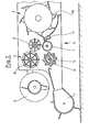
- Fig. 1 the basic structure of a forage harvester is shown schematically in longitudinal section. It is irrelevant to the invention whether it is an attached or self-propelled chopper.
- a screw 2 with opposite screw flights brings the crop together towards the center and transfers it to a feed device 3, from where it is passed on to the chopping elements 4.
- a feed device 3 from where it is passed on to the chopping elements 4.
- other attachments such as. B. find a device for harvesting row maize, use.
- the feed device 3 is made of lower, drivable and stationary in the machine frame 5 mounted feed rollers 6 and 7 and upper, with respect to the machine frame 5 pivotally mounted feed rollers 8 and 9 are formed. These feed rollers are pulled towards the lower rollers 6 and 7 by tension springs (not shown) and have the task of compacting the crop in addition to conveying in the direction of the chopping elements 4 to form a mat.
- the chopping organs 4 consist in a known manner of a revolving knife drum 1 0 , which cooperates with a stationary shearbar 11.
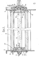
- a signal generator device 12 is preferably fixed in position in the front, lower feed roller 6 with respect to the machine frame 5. In order to ensure a trouble-free function of the signal generator device, external influences that would lead to a change in position and / or shape of the signal generator device are of to keep the latter away. In order to achieve this goal, the signal generator device according to FIG. 2 is mounted as follows.
- the signal generator device 12 consists of several permanent magnets, to which several induction coils are assigned.
- the connections of these induction coils, which are connected to a signal processing device, not shown, are designated by the reference number 13.
- the signal generator device 12 can also be configured in any desired way, since it is only important for its intended function to detect foreign objects carried along.
- the signal generator device 12 is on the one hand with an axle stub 14 on the left in the drawing and on the other hand with one in the Drawing right stub axle 15 firmly connected. It is important that the signal generating device 12 is arranged in a stationary, fixed manner with respect to the machine frame 5.
- the front, lower feed roller 6 is designed as a hollow roller. In order to ensure the function of the device for recognizing ferrous material, it is made of non-magnetizable material, in the exemplary embodiment shown made of plastic.
- the drive shaft stub 17 has a bearing collar 18 which carries a self-aligning ball bearing 19.
- the fixed outer ring 2o of the self-aligning ball bearing 19 is held by a two-part bearing housing 21.
- the bearing housing 21 is fixed to the machine frame 5 by means of a plurality of fastening screws 22 distributed over the circumference.
- the stub axle 15 has a bearing pin 23 which is mounted in a recess 25 of the drive shaft stub 17 with the aid of a further ball bearing 24.
- the ball bearing 24 and the self-aligning ball bearing 19 are arranged such that they have a common center point 26.
- changes in shape of the machine frame 5 or changes in shape of the feed roller 6 and the drive shaft stub 17 can be absorbed in such a way that no change in shape or position of the stub axle 15 and thus the signal generator device 12 are caused. In this way, unwanted disturbance variables can be reliably eliminated.
- the end of the feed roller 6 on the left in the drawing is supported on a ring 27.
- a bearing flange 28 firmly connected to the machine frame 5 carries a self-aligning ball bearing 29, the outer ring of which is inserted in the ring 27 in a rotationally fixed manner.
- Changes in shape and position of the machine frame 5 or the left end of the feed roller 6 therefore have no influence on the position of the stub axle 14. Since the stub axle 14 must be arranged in a fixed position with respect to the machine frame 5, a securing against rotation of the stub axle 14 is necessary. To eliminate external influences here, there is a rotation of a relatively thin-walled web 3 0, on the one hand communicates with the stub shaft 14 in a rotationally fixed connection, and on the other hand fixed by fastening screws 31 to the machine frame. 5
- the web 3o only fulfills the task of securing the stub axle 14 in the position shown. Due to its elastic design, it is able to absorb deformations caused by external influences without any change in the position of the stub axle 14.
- the above-described mounting of the stub axles 14 and 15 ensures that the signal generator device 12 is arranged without any external influences. That way, how The practical use of the device designed according to the invention for detecting iron-containing material proves that undesirable sources of interference are eliminated.
Abstract
Description
Die Erfindung betrifft eine Vorrichtung zum Erkennen von eisenhaltigem Material in Feldhäckslern mit den Merkmalen des Oberbegriffs des Hauptanspruchs.The invention relates to a device for recognizing ferrous material in forage harvesters with the features of the preamble of the main claim.
Eine Vorrichtung zum Erkennen von eisenhaltigem Material in Feldhäckslern ist beispielsweise aus der DE-OS 25 So 8o5 bekannt geworden. Der Feldhäcksler selbst ist hierbei in herkömmlicher Weise aufgebaut. Den Häckselorganen, bestehend aus einer umlaufenden Messertrommel und einer Gegenschneide, ist eine Zuführungsvorrichtung vorgeschaltet, die sich aus zwei unteren, ortsfest im Maschinenrahmen angeordneten sowie zwei oberen, zum Zwecke der Anpassung an unterschiedlich dicke Erntegutmatten schwenkbeweglich gelagerten oberen Zuführungsrollen zusammensetzt. Diese paarweise zusammenwirkenden unteren und oberen Zuführungsrollen haben die Aufgabe, das aufgenommene Erntegut zu verdichten und den Häckselorganen zuzuführen. Bei der bekannten Vorrichtung ist eine Signalerzeugereinrichtung in der vorderen, unten liegenden Zuführungsrolle installiert. Die bekannte Signalerzeugereinrichtung umfaßt einen Signalerzeuger für ein konstantes Signal sowie eine Magnetspuleneinrichtung, die in der Lage ist, den Signalerzeuger zu unterbrechen, falls unerwünschte Gegenstände in den Bereich der Einzugswalzen gelangen.A device for detecting ferrous material in forage harvesters has become known, for example, from DE-OS 25 So 8o5. The forage harvester itself is constructed in a conventional manner. The chopping elements, consisting of a revolving knife drum and a shear bar, are preceded by a feed device, which consists of two lower, fixedly arranged in the machine frame and two upper, for the purpose of adaptation to different thickness crop mats pivotally mounted upper feed rollers. These paired lower and upper feed rollers have the task of compacting the harvested crop and feeding it to the chopping organs. In the known device, a signal generating device is installed in the front, lower feed roller. The well-known signal Generator device comprises a signal generator for a constant signal and a magnetic coil device which is able to interrupt the signal generator if undesired objects get into the area of the feed rollers.
Bei der erfindungsgemäßen Vorrichtung zum Erkennen von eisenhaltigem Material wird nach dem sogenannten Induktionsprinzip gearbeitet. Die Signalerzeugereinrichtung, die selbst nicht Gegenstand des Schutzbegehrens ist,weist mehrere Spulenwicklungen auf, die ein stationäres Magnetfeld umschließen. Sobald ein ferromagnetischer Körper in den Bereich des stationären Magnetfeldes gelangt, wird eine Spannung induziert. Dieses Signal wird dazu herangezogen, eine Reversiereinrichtung für die Zuführungsvorrichtung zu betätigen, sodaß der unerwünschte ferromagnetische Körper nicht zu den Häckselorganen gelangen kann.In the device according to the invention for recognizing ferrous material, the so-called induction principle is used. The signal generating device, which itself is not the subject of the request for protection, has a plurality of coil windings which enclose a stationary magnetic field. As soon as a ferromagnetic body reaches the area of the stationary magnetic field, a voltage is induced. This signal is used to actuate a reversing device for the feed device so that the undesired ferromagnetic body cannot reach the chopping organs.
Es hat sich herausgestellt, daß die praktische Anwendung einer Vorrichtung zum Erkennen von eisenhaltigem Material der in Rede stehenden Bauart eine Reihe von Problemen aufwirft. Zum Teil sind hier Forderungen zu erfüllen, die sich widersprechen. Einerseits muß beispielsweise der Wirkungsbereich des Magnetfeldes so groß gewählt werden, daß die maximal mögliche Dicke der zugeführten Erntegutmatte durchdrungen wird, um auch ferromagnetische Teile erfassen zu können, die auf der Oberseite dieser Schicht mitgeführt werden. Um unter dieser Bedingung eine sichere Funktion zu gewährleisten, muß dafür Sorge getragen werden, daß Störungen,.die aus umlaufenden Eisenteilen der Maschine selbst resultieren, ausgeschaltet werden. Hierzu wurde vorgeschlagen, die in der Nähe des Magnetfeldes umlaufenden Bauteile aus nicht-magnetisierbarem Material zu fertigen.It has been found that the practical application of a device for the detection of ferrous material of the type in question poses a number of problems. In some cases, there are requirements that contradict each other. On the one hand, the effective range of the magnetic field, for example, must be chosen so large that the maximum possible thickness of the supplied crop mat is penetrated in order to also be able to detect ferromagnetic parts which are carried on the top of this layer. In order to ensure safe functioning under this condition, care must be taken to ensure that faults which result from rotating iron parts of the machine itself are switched off. For this purpose, it has been proposed to manufacture the components rotating in the vicinity of the magnetic field from non-magnetizable material.
Da die Materialeigenschaften der zu ortenden Fremdkörper recht unterschiedlich sein können (Teile, die einen relativ hohen Eisengehalt aufweisen, wie beispielsweise Schraubenbolzen bzw. Teile, bei denen der Eisenanteil relativ gering ist wie z. B. Federstahl-Zinken von Heuwerbungsmaschinen), muß die Empfindlichkeit der Signalerzeugereinrichtung, um eben sämtliche Fremdkörper erfassen zu können, relativ hoch gewählt werden. Es hat sich herausgestellt, daß die Abschirmung rotierender Bauelemente von der Signalerzeugereinrichtung zwar grundsätzlich notwendig ist, daß jedoch hierdurch nicht sämtliche Quellen für mögliche Störsignale, die ein unbeabsichtigtes Reversieren der Einzugsorgane bewirken, ausgeschaltet sind. Beispielsweise ist der Maschinenrahmen während des normalen Betriebes des Feldhäckslers ständig wechselnden Beanspruchungen ausgesetzt, die zu wechselnden elastischen Verformungen des Rahmens führen. Derartige Formänderungen bewirken das Auslösen von Störsignalen, sofern mit ihnen eine Form- oder Lageänderung der Signalerzeugungseinrichtung einhergeht. Es hat sich herausgestellt, daß schon geringe Form- bzw. Lageveränderungen der Signalerzeugungseinrichtung zu derartigen Störsignalen führen. Umgekehrt können derartige Signale auch dadurch ausgelöst werden, daß die, die Signalerzeugereinrichtung umschließende Zuführungsrolle nicht rückwirkungsfrei in Bezug auf die Signalerzeugereinrichtung gelagert ist, sodaß elastische Verformungen dieser Rolle zu einer elastischen Verformung der Signalerzeugereinrichtung führen bzw., daß zumindest ihre Lage zum Rahmen der Maschine derart verändert wird, daß ein solches unerwünschtes Störsignal auftritt.Since the material properties of the foreign objects to be located can be quite different (Parts that have a relatively high iron content, such as bolts or parts in which the iron content is relatively low, such as spring steel tines on haymaking machines), must be sensitive to the signal generator device in order to be able to detect all foreign bodies. be chosen relatively high. It has been found that the shielding of rotating components by the signal generating device is in principle necessary, but that this does not mean that all sources of possible interference signals which cause the feed elements to be inadvertently reversed are switched off. For example, the machine frame is subjected to constantly changing stresses during normal operation of the forage harvester, which lead to changing elastic deformations of the frame. Such changes in shape cause interference signals to be triggered, provided they are used to change the shape or position of the signal generation direction. It has been found that even slight changes in shape or position of the signal generating device lead to such interference signals. Conversely, such signals can also be triggered by the fact that the feed roller surrounding the signal generator device is not mounted without feedback with respect to the signal generator device, so that elastic deformations of this roller lead to an elastic deformation of the signal generator device or that at least its position relative to the frame of the machine is such is changed that such an undesirable interference signal occurs.
Der vorliegenden Erfindung liegt die Aufgabe zugrunde, unerwünschte Störsignale bei einer Vorrichtung der in Rede stehenden Gattung durch eine praktisch von äußeren Einflüssen rückwirkungsfrei gelagerte Signalerzeugereinrichtung auszuschalten.The present invention is based on the object of eliminating unwanted interference signals in a device of the type in question by means of a signal generator device which is practically non-reactive from external influences.
Die Erfindung löst die gestellte Aufgabe durch die im Kennzeichen des Hauptanspruchs angegebenen Maßnahmen.The invention solves this problem by the measures specified in the characterizing part of the main claim.
Ein bevorzugtes Ausführungsbeispiel der Erfindung wird nachstehend anhand der Zeichnungen näher erläutert.A preferred embodiment of the invention is explained below with reference to the drawings.
Es zeigen:
- Fig. 1 einen Feldhäcksler mit einer Vorrichtung zum Erkennen von eisenhaltigen Fremdkörpern in schematischer , teils geschnittener Seitenansicht;
- Fig. 2 die Lagerung einer Signalerzeugereinrichtung innerhalb der vorderen, unteren Zuführungsrolle eines Feldhäckslers nach Fig. 1.
- Figure 1 shows a forage harvester with a device for detecting foreign bodies containing iron in a schematic, partially sectioned side view.
- 2 shows the storage of a signal generating device within the front, lower feed roller of a forage harvester according to FIG. 1.
In Fig. 1 ist der grundsätzliche Aufbau eines Feldhäckslers schematisch im Längsschnitt wiedergegeben. Für die Erfindung ist es hierbei bedeutungslos, ob es sich um einen angebauten oder selbstfahrenden Häcksler handelt.In Fig. 1 the basic structure of a forage harvester is shown schematically in longitudinal section. It is irrelevant to the invention whether it is an attached or self-propelled chopper.
Ober eine Pick-up 1 wird das am Boden liegende Erntegut aufgenommen. Eine Schnecke 2 mit entgegengesetzt gerichteten Schneckengängen führt das Erntegut zur Mitte hin zusammen und übergibt es an eine Zuführungsvorrichtung 3, von wo es an die Häckselorgane 4 weitergegeben wird. Anstelle der hier gezeigten Pick-up können selbstverständlich auch andere Vorsatzgeräte, wie z. B. eine Vorrichtung zum Ernten von in Reihe stehendem Mais, Verwendung finden.The crop lying on the ground is picked up via a pick-up 1. A screw 2 with opposite screw flights brings the crop together towards the center and transfers it to a
Die Zuführvorrichtung 3 wird aus unteren, antreibbaren und ortsfest im Maschinenrahmen 5 gelagerten Zuführungsrollen 6 und 7 sowie oberen, in Bezug auf den Maschinenrahmen 5 schwenkbeweglich gelagerten Zuführungsrollen 8 und 9 gebildet. Diese Zuführungsrollen werden durch nicht dargestellte Zugfedern in Richtung auf die unteren Rollen 6 und 7 gezogen und haben die Aufgabe, das Erntegut neben der Förderung in Richtung auf die Häckselorgane 4 zu einer Matte zu verdichten.The
Die Häckselorgane 4 bestehen in bekannter Weise aus einer umlaufenden Messertrommel 10, die mit einer ortsfesten Gegenschneide 11 zusammenwirkt.The
Vorzugsweise in der vorderen, unteren Einzugsrolle 6 ist eine Signalerzeugereinrichtung 12 in Bezug auf den Maschinenrahmen 5 ortsfest gelagert. Um eine störungsfreie Funktion der Signalerzeugereinrichtung zu gewährleisten, sind äußere Einflüsse, die zu einer Lage- und / oder Formveränderung der Signalerzeugereinrichtung führen würden, von letzterer fernzuhalten. Um dieses Ziel zu erreichen, ist die Signalerzeugereinrichtung entsprechend Fig. 2 wie folgt gelagert.A
Die Signalerzeugereinrichtung 12 besteht im dargestellten Fall aus mehreren Permanentmagneten, denen mehrere Induktionsspulen zugeordnet sind. Die Anschlüsse dieser Induktionsspulen, die mit einer nicht dargestellten Signalverarbeitungseinrichtung verbunden sind, sind mit der Bezugsziffer 13 bezeichnet. Anstelle des beschriebenen Aufbaues der Signalerzeugereinrichtung kann diese auch beliebig abweichend ausgestaltet sein, da es für ihre bestimmungsgemäße Funktion nur darauf ankommt, mitgeführte Fremdkörper zu erfassen.In the case shown, the
Die Signalerzeugereinrichtung 12 ist einerseits mit einem in der Zeichnung links liegenden Achsstummel 14 und andererseits mit einem in der Zeichnung rechts liegenden Achsstummel 15 fest verbunden. Wichtig ist, daß die Signalerzeugereinrichtung 12 ortsfest feststehend in Bezug auf den Maschinenrahmen 5 angeordnet ist. Die vordere, untere Zuführungsrolle 6 ist als Hohlwalze ausgebildet. Sie ist, um die Funktion der Vorrichtung zum Erkennen von eisenhaltigem Material zu gewährleisten, aus nicht-magnetisierbarem Werkstoff, im dargestellten Ausführungsbeispiel aus Kunststoff, gefertigt.The
Die in der Zeichnung rechts liegenden Lagerungen für den Achsstummel 15 der Signalerzeugereinrichtung 12 und der drehantreibbaren Zuführungsrolle 6 sind wie folgt vorgenommen:
- Das in der Zeichnung rechts liegende Ende der
Zuführungsrolle 6 ist über mehrere, am Umfang der Rolle verteilte, radialgerichtete Befestigungsschrauben 16 mit einem etwa glockenförmigausgebildeten Antriebswellenstummel 17 drehfest verbunden. Zum Antrieb derZuführungsrolle 6 steht das freie Ende desAntriebswellenstummels 17 mit einer nicht dargestellten Antriebswelle in drehfester Verbindung.
- The end of the
feed roller 6 on the right in the drawing is connected in a rotationally fixed manner via a plurality of radially directedfastening screws 16 distributed around the circumference of the roller to an approximately bell-shaped stub shaft 17. To drive thefeed roller 6 is the free end of theDrive shaft stub 17 with a drive shaft, not shown, in a rotationally fixed connection.
Der Antriebswellenstummel 17 weist einen Lagerbund 18 auf, der ein Pendelkugellager 19 trägt. Der feststehende Außenring 2o des Pendelkugellagers 19 wird durch ein zweiteiliges Lagergehäuse 21 gehalten. Mittels mehrerer am Umfang verteilter Befestigungsschrauben 22 ist das Lagergehäuse 21 am Maschinenrahmen 5 festgelegt.The
Der Achsstummel 15 weist einen Lagerzapfen 23 auf, der mit Hilfe eines weiteren Kugellagers 24 in einer Ausdrehung 25 des Antriebswellenstummels 17 gelagert ist.The
Das Kugellager 24 und das Pendel-Kugellager 19 sind derart angeordnet, daß sie einen gemeinsamen Mittelpunkt 26 aufweisen. Durch das Pendel-Kugellager 19 und dessen Lage zum weiteren Kugellager 24 können auftretende Formveränderungen des Maschinenrahmens 5 bzw. Formänderungen der Zuführungsrolle 6 und des Antriebswellenstummels 17 derart aufgefangen werden, daß keine Form- bzw. Lageveränderung des Achsstummels 15 und damit der Signalerzeugereinrichtung 12 hervorgerufen werden. Auf diese Weise lassen sich zuverlässig unerwünschte Störgrößen ausschalten.The ball bearing 24 and the self-aligning ball bearing 19 are arranged such that they have a
Das in der Zeichnung links liegende Ende der Zuführungsrolle 6 stützt sich auf einem Ring 27 ab. Ein mit dem Maschinenrahmen 5 fest verbundener Lagerflansch 28 trägt ein Pendelkugellager 29, dessen Außenring drehfest in den Ring 27 eingefügt ist. Auf diese Weise wird das in der Zeichnung links liegende Ende der Zuführungsrolle 6 über den Lagerflansch 28 direkt am Maschinenrahmen 5 abgestützt, ohne daß hier eine Verbindung zum Achsstummel 14 besteht. Auftretende Form- und Lageveränderungen des Maschinenrahmens 5 bzw. des linken Endes der Zuführungsrolle 6 haben daher keinen Einfluß auf die Lage des Achsstummels 14. Da der Achsstummel 14 in Bezug auf den Maschinenrahmen 5 ortsfest angeordnet sein muß, ist eine Sicherung gegen Verdrehung des Achsstummels 14 notwendig. Um hier äußere Einflüsse auszuschalten, besteht die Verdrehsicherung aus einem relativ dünnwandigen Steg 30, der einerseits mit dem Achsstummel 14 in drehfester Verbindung steht und andererseits über Befestigungsschrauben 31 am Maschinenrahmen 5 festgelegt ist.The end of the
Der Steg 3o erfüllt lediglich die Aufbabe, den Achsstummel 14 in seiner dargestellten Lage zu sichern. Durch seine elastische Ausbildung ist er in der Lage, durch äußere Einflüsse hervorgerufene Verformungen in sich selbst aufzunehmen, ohne daß hierbei eine Lageveränderung des Achsstummels 14 auftritt. Durch die vorstehend beschriebene Lagerung der Achsstummel 14 und 15 ist eine von äußeren Einflüssen rückwirkungsfreie Anordnung der Signalerzeugereinrichtung 12 gewährleistet. Auf diese Weise können, wie der praktische Einsatz der erfindungsgemäß ausgestalteten Vorrichtung zum Erkennen von eisenhaltigem Material beweist, unerwünschte Störquellen ausgeschaltet werden.The web 3o only fulfills the task of securing the
Claims (7)
Priority Applications (3)
| Application Number | Priority Date | Filing Date | Title |
|---|---|---|---|
| AT81103543T ATE18489T1 (en) | 1981-05-09 | 1981-05-09 | DEVICE FOR DETECTING FERROUS MATERIAL IN FELDHAECKSLERN. |
| DE8181103543T DE3174036D1 (en) | 1981-05-09 | 1981-05-09 | Metal detector apparatus in crop harvesters |
| EP81103543A EP0064566B1 (en) | 1981-05-09 | 1981-05-09 | Metal detector apparatus in crop harvesters |
Applications Claiming Priority (1)
| Application Number | Priority Date | Filing Date | Title |
|---|---|---|---|
| EP81103543A EP0064566B1 (en) | 1981-05-09 | 1981-05-09 | Metal detector apparatus in crop harvesters |
Publications (2)
| Publication Number | Publication Date |
|---|---|
| EP0064566A1 true EP0064566A1 (en) | 1982-11-17 |
| EP0064566B1 EP0064566B1 (en) | 1986-03-12 |
Family
ID=8187705
Family Applications (1)
| Application Number | Title | Priority Date | Filing Date |
|---|---|---|---|
| EP81103543A Expired EP0064566B1 (en) | 1981-05-09 | 1981-05-09 | Metal detector apparatus in crop harvesters |
Country Status (3)
| Country | Link |
|---|---|
| EP (1) | EP0064566B1 (en) |
| AT (1) | ATE18489T1 (en) |
| DE (1) | DE3174036D1 (en) |
Cited By (5)
| Publication number | Priority date | Publication date | Assignee | Title |
|---|---|---|---|---|
| EP0904684A1 (en) * | 1997-09-24 | 1999-03-31 | CLAAS Selbstfahrende Erntemaschinen GmbH | Reversing device of foreign objects in harvesting machines |
| BE1019497A5 (en) * | 2008-12-10 | 2012-08-07 | Deere & Co | DEVICE FOR DISTINGUISHING A FOREIGN BODY HAVING PENETRATING IN A HARVESTING MACHINE. |
| BE1021657B1 (en) * | 2012-02-09 | 2015-12-22 | Deere & Company | FEED ASSEMBLY FOR A FIELD CHECKER |
| CN109969809A (en) * | 2017-12-27 | 2019-07-05 | 中车大同电力机车有限公司 | A kind of feeding roller installation drive mechanism |
| DE102018003555A1 (en) * | 2018-05-03 | 2019-11-07 | Maschinenfabrik Bernard Krone GmbH & Co. KG | Feed roller for a harvester |
Citations (3)
| Publication number | Priority date | Publication date | Assignee | Title |
|---|---|---|---|---|
| US3972156A (en) * | 1975-02-24 | 1976-08-03 | Sperry Rand Corporation | Speed-independent static magnetic field metal detector |
| GB2013072A (en) * | 1977-12-02 | 1979-08-08 | Sperry Rand Nv | Crop harvesting machines |
| FR2466184A1 (en) * | 1979-10-04 | 1981-04-10 | Claas Ohg | HARVESTING HARVESTER WITH METAL DETECTION |
-
1981
- 1981-05-09 DE DE8181103543T patent/DE3174036D1/en not_active Expired
- 1981-05-09 AT AT81103543T patent/ATE18489T1/en active
- 1981-05-09 EP EP81103543A patent/EP0064566B1/en not_active Expired
Patent Citations (3)
| Publication number | Priority date | Publication date | Assignee | Title |
|---|---|---|---|---|
| US3972156A (en) * | 1975-02-24 | 1976-08-03 | Sperry Rand Corporation | Speed-independent static magnetic field metal detector |
| GB2013072A (en) * | 1977-12-02 | 1979-08-08 | Sperry Rand Nv | Crop harvesting machines |
| FR2466184A1 (en) * | 1979-10-04 | 1981-04-10 | Claas Ohg | HARVESTING HARVESTER WITH METAL DETECTION |
Cited By (7)
| Publication number | Priority date | Publication date | Assignee | Title |
|---|---|---|---|---|
| EP0904684A1 (en) * | 1997-09-24 | 1999-03-31 | CLAAS Selbstfahrende Erntemaschinen GmbH | Reversing device of foreign objects in harvesting machines |
| DE19742060B4 (en) * | 1997-09-24 | 2005-02-03 | Claas Selbstfahrende Erntemaschinen Gmbh | Foreign body recycling device on harvesting machines o. The like. |
| BE1019497A5 (en) * | 2008-12-10 | 2012-08-07 | Deere & Co | DEVICE FOR DISTINGUISHING A FOREIGN BODY HAVING PENETRATING IN A HARVESTING MACHINE. |
| BE1021657B1 (en) * | 2012-02-09 | 2015-12-22 | Deere & Company | FEED ASSEMBLY FOR A FIELD CHECKER |
| CN109969809A (en) * | 2017-12-27 | 2019-07-05 | 中车大同电力机车有限公司 | A kind of feeding roller installation drive mechanism |
| DE102018003555A1 (en) * | 2018-05-03 | 2019-11-07 | Maschinenfabrik Bernard Krone GmbH & Co. KG | Feed roller for a harvester |
| DE102018003555B4 (en) * | 2018-05-03 | 2020-03-12 | Maschinenfabrik Bernard Krone GmbH & Co. KG | Feed roller for a harvester |
Also Published As
| Publication number | Publication date |
|---|---|
| ATE18489T1 (en) | 1986-03-15 |
| EP0064566B1 (en) | 1986-03-12 |
| DE3174036D1 (en) | 1986-04-17 |
Similar Documents
| Publication | Publication Date | Title |
|---|---|---|
| DE2265809C2 (en) | Harvesting machine with a metal foreign body detection device | |
| DE102012223768B4 (en) | Foreign body detection device for an agricultural harvester | |
| DE2552805C2 (en) | Harvesting machine, especially forage harvester | |
| EP0408850B1 (en) | Self-propelled harvesting machine | |
| DE19524752B4 (en) | Device and method for measuring throughput in an agricultural harvesting machine | |
| DE3213713A1 (en) | DETECTING DEVICE FOR STONES IN HARVESTING MACHINES | |
| DE2430147A1 (en) | DEVICE FOR DETECTING THE CROSS-THROUGH ARTICLES MADE OF MAGNETIC MATERIAL THROUGH A ROOM ZONE AND HARVESTING MACHINE EQUIPPED WITH THE DEVICE | |
| DE2940201A1 (en) | FIELD CHOPPER WITH METAL DETECTOR | |
| DE19803336A1 (en) | Rotary conveyor with a rotary body and at least one driver and harvester with such a rotary conveyor | |
| DE3211819C2 (en) | ||
| EP0931446B1 (en) | Measuring device in a harvesting machine | |
| DE19632868C2 (en) | Processing device with electronic control device for an agricultural processing machine | |
| DE102005008448A1 (en) | Storage of a Gutförder- and / or Gutbearbeitungselements for a harvester | |
| DE102018105858A1 (en) | Attachment of an agricultural harvesting vehicle and agricultural harvesting vehicle | |
| DE19912407A1 (en) | Transporter with metal detection device for use in harvesting or chaffing machinery has a roller with magnets contained internally, the fields of which are changed by the presence of magnetic metallic parts | |
| EP0064566A1 (en) | Metal detector apparatus in crop harvesters | |
| DE102012223432B3 (en) | Arrangement for adjusting discharge accelerator gap between envelope circle of forage harvester and concave portion of rotor casing, has actuator that adjusts gap of discharge accelerator to predetermined size based on sensor signals | |
| DE10120204A1 (en) | Pick-up for agricultural harvesting machines with a hold-down device | |
| EP3449718B1 (en) | Weighing device and harvesting device | |
| EP1523876B1 (en) | Conveyor with a metal detecting device | |
| EP0153621B1 (en) | Drum chopper with a recomminution device | |
| EP1632128A1 (en) | Method and apparatus for the adjustment of the sensitivity of a foreign object detector | |
| DE3939659C2 (en) | ||
| DE10332395A1 (en) | harvester | |
| EP3706546B1 (en) | Pick-up with metal detector |
Legal Events
| Date | Code | Title | Description |
|---|---|---|---|
| PUAI | Public reference made under article 153(3) epc to a published international application that has entered the european phase |
Free format text: ORIGINAL CODE: 0009012 |
|
| AK | Designated contracting states |
Designated state(s): AT BE CH DE FR GB NL |
|
| 17P | Request for examination filed |
Effective date: 19821208 |
|
| GRAA | (expected) grant |
Free format text: ORIGINAL CODE: 0009210 |
|
| AK | Designated contracting states |
Kind code of ref document: B1 Designated state(s): AT BE CH DE FR GB LI NL |
|
| REF | Corresponds to: |
Ref document number: 18489 Country of ref document: AT Date of ref document: 19860315 Kind code of ref document: T |
|
| REF | Corresponds to: |
Ref document number: 3174036 Country of ref document: DE Date of ref document: 19860417 |
|
| RAP2 | Party data changed (patent owner data changed or rights of a patent transferred) |
Owner name: KLOECKNER-HUMBOLDT-DEUTZ AG ZWEIGNIEDERLASSUNG FAH |
|
| PGFP | Annual fee paid to national office [announced via postgrant information from national office to epo] |
Ref country code: AT Payment date: 19860509 Year of fee payment: 6 |
|
| ET | Fr: translation filed | ||
| PGFP | Annual fee paid to national office [announced via postgrant information from national office to epo] |
Ref country code: NL Payment date: 19860531 Year of fee payment: 6 |
|
| NLXE | Nl: other communications concerning ep-patents (part 3 heading xe) |
Free format text: IN PAT.BUL.11/86,PAGES 1292 AND 1351 SHOULD BE MODIFIED INTO:KLOECKNER-HUMBOLDT-DEUTZ AG ZWEIGNIEDERLASSUNG FAHR |
|
| BECN | Be: change of holder's name |
Effective date: 19860312 |
|
| PLBE | No opposition filed within time limit |
Free format text: ORIGINAL CODE: 0009261 |
|
| STAA | Information on the status of an ep patent application or granted ep patent |
Free format text: STATUS: NO OPPOSITION FILED WITHIN TIME LIMIT |
|
| 26N | No opposition filed | ||
| PG25 | Lapsed in a contracting state [announced via postgrant information from national office to epo] |
Ref country code: AT Effective date: 19870509 |
|
| PG25 | Lapsed in a contracting state [announced via postgrant information from national office to epo] |
Ref country code: LI Effective date: 19870531 Ref country code: CH Effective date: 19870531 |
|
| BERE | Be: lapsed |
Owner name: KLOCKNER-HUMBOLDT-DEUTZ A.G. ZWEIGNIEDERLASSUNG F Effective date: 19870531 |
|
| PG25 | Lapsed in a contracting state [announced via postgrant information from national office to epo] |
Ref country code: NL Effective date: 19871201 |
|
| NLV4 | Nl: lapsed or anulled due to non-payment of the annual fee | ||
| PG25 | Lapsed in a contracting state [announced via postgrant information from national office to epo] |
Ref country code: FR Free format text: LAPSE BECAUSE OF NON-PAYMENT OF DUE FEES Effective date: 19880129 |
|
| REG | Reference to a national code |
Ref country code: CH Ref legal event code: PL |
|
| PG25 | Lapsed in a contracting state [announced via postgrant information from national office to epo] |
Ref country code: DE Effective date: 19880202 |
|
| GBPC | Gb: european patent ceased through non-payment of renewal fee | ||
| REG | Reference to a national code |
Ref country code: FR Ref legal event code: ST |
|
| PG25 | Lapsed in a contracting state [announced via postgrant information from national office to epo] |
Ref country code: GB Free format text: LAPSE BECAUSE OF NON-PAYMENT OF DUE FEES Effective date: 19881121 |
|
| PG25 | Lapsed in a contracting state [announced via postgrant information from national office to epo] |
Ref country code: BE Effective date: 19890531 |