EP0063984B1 - Odometer with planetary gear reduction mechanism for a two-wheeled vehicle or the like - Google Patents
Odometer with planetary gear reduction mechanism for a two-wheeled vehicle or the like Download PDFInfo
- Publication number
- EP0063984B1 EP0063984B1 EP82400641A EP82400641A EP0063984B1 EP 0063984 B1 EP0063984 B1 EP 0063984B1 EP 82400641 A EP82400641 A EP 82400641A EP 82400641 A EP82400641 A EP 82400641A EP 0063984 B1 EP0063984 B1 EP 0063984B1
- Authority
- EP
- European Patent Office
- Prior art keywords
- teeth
- gear
- driving
- eccentric
- recorder according
- Prior art date
- Legal status (The legal status is an assumption and is not a legal conclusion. Google has not performed a legal analysis and makes no representation as to the accuracy of the status listed.)
- Expired
Links
Images
Classifications
-
- G—PHYSICS
- G01—MEASURING; TESTING
- G01C—MEASURING DISTANCES, LEVELS OR BEARINGS; SURVEYING; NAVIGATION; GYROSCOPIC INSTRUMENTS; PHOTOGRAMMETRY OR VIDEOGRAMMETRY
- G01C22/00—Measuring distance traversed on the ground by vehicles, persons, animals or other moving solid bodies, e.g. using odometers, using pedometers
-
- G—PHYSICS
- G06—COMPUTING; CALCULATING OR COUNTING
- G06M—COUNTING MECHANISMS; COUNTING OF OBJECTS NOT OTHERWISE PROVIDED FOR
- G06M1/00—Design features of general application
- G06M1/04—Design features of general application for driving the stage of lowest order
- G06M1/06—Design features of general application for driving the stage of lowest order producing continuous revolution of the stage, e.g. with gear train
- G06M1/062—Design features of general application for driving the stage of lowest order producing continuous revolution of the stage, e.g. with gear train for drum type indicating means
-
- F—MECHANICAL ENGINEERING; LIGHTING; HEATING; WEAPONS; BLASTING
- F16—ENGINEERING ELEMENTS AND UNITS; GENERAL MEASURES FOR PRODUCING AND MAINTAINING EFFECTIVE FUNCTIONING OF MACHINES OR INSTALLATIONS; THERMAL INSULATION IN GENERAL
- F16H—GEARING
- F16H1/00—Toothed gearings for conveying rotary motion
- F16H1/28—Toothed gearings for conveying rotary motion with gears having orbital motion
- F16H2001/2881—Toothed gearings for conveying rotary motion with gears having orbital motion comprising two axially spaced central gears, i.e. ring or sun gear, engaged by at least one common orbital gear wherein one of the central gears is forming the output
Definitions
- the meters usually used have, inside a housing extended by a control cable entry, a totalizing indicator system and a reduction mechanism interposed between this system and a rotary axis integral with the control cable.
- the reduction mechanism includes angle references by worm.
- the present invention therefore aims to make it simpler to produce and assemble the reduction mechanism while reducing its size.
- the object of this invention is in fact an odometer, the reduction mechanism of which comprises an eccentric satellite carrying two external teeth, coaxial and superimposed, having, different numbers of teeth, which are engaged one with a fixed teeth and the other with a free planetary in rotation, an eccentric integral with the axis of connection to the control cable which drives the satellite to cause the rotation of the planetary, the latter comprising at its upper part an axial spiral toothing driving the totalizing indicator system .
- the various organs satellite, fixed or planetary toothing, for example, consist of crowns of small axial height which are simply placed one above the other or one inside the other and must simply be arranged so as to be brought into contact without particular precision.
- the meter object of the invention also includes a magnetic tachometer, the eccentric comprising a central recess for housing a magnetic disc and a bell secured to an indicator needle.
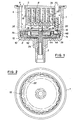
- the counter shown in FIG. 1 comprises a box 1 which is extended at one of its ends by a control cable entry 2. At its opposite end the box 1 is closed by a plate 4 which comprises on the one hand a plate 5 pierced with a reading window and on the other hand wings 6 for supporting counting members 8.
- the side wall of the housing 1 has at the bottom 3 a circular internal toothing 10 and, slightly above this toothing, an internal shoulder 12 which delimits a housing for an annular sun gear 14.
- the sun gear 14 has on the one hand an internally toothed ring 15 and on the other hand, at its upper part, a spiral toothing 16 whose teeth are axially directed.
- the sun gear 14 is free to rotate inside the cylindrical housing 1 on the shoulder 12. Its internal toothing 15 is however engaged with the upper toothing 18 of a satellite 20 mounted eccentrically in the housing 1.
- the satellite 20 rotates on the bottom 3 of the cylindrical housing and has a second external toothing 22 which engages with the internal toothing 10 of the housing.
- the two external toothing 18 and 22 are thus coaxial and superimposed although separated by a distance which corresponds substantially to the distance between the internal toothing 10 of the housing and the internally toothed ring 15 of the sun gear.
- the teeth 18 and 22 of the satellite 20, however, have different numbers of teeth, the lower teeth 22 also having a number of teeth less than that of the internal teeth 10 of the housing, while the upper teeth 18 have a similar number of teeth. to that of the inner ring 15 of the planet.
- the internal toothing of the housing has twenty-one teeth
- the lower toothing 22 of the satellite has only nineteen, the upper toothing of the satellite as well as the sun gear ring having twenty teeth.
- the internal surface 21 of the annular satellite 20 is also in contact with an eccentric 24 which is integral with an axis 26 housed in the extension 2 of the housing 1 and intended to be connected to the control cable and to rotate with the latter.
- the eccentric 24 preferably comprises two circular discs offset by 180 ° and fixed on the same axis 24 so that the maximum distance between the center of this axis and their peripheral edge corresponds to the internal diameter of the satellite 20.
- the lower disc 27 has in addition an axial thickness analogous to that of the satellite 20. As a result, this lower disc 27 is always in contact at one point with the satellite 20 while the upper disc 28 presses at an opposite point on the satellite and maintains it in position at inside the housing (Fig. 1).
- the axis 26 and the eccentric 24 are also rotated.
- the lower disc 27 of the ex centric 24 alternately pushes the satellite 20 in two opposite directions during each of its rotations and thus moves it tooth to tooth around the fixed internal toothing 10 of the housing.
- the upper teeth 18 of the satellite have a different number of teeth, it causes the planet 14 to move by a distance which is a function of this difference, and consequently that of the spiral teeth 16 of the upper part of this planet.
- the spiral toothing 16 forms an angular gear with a pinion 30 which is mounted to rotate freely on an axis 32 carried by the two opposite wings 6 of the plate 4.
- the number of teeth of the pinion 30 is preferably equal to that of spiral teeth of the toothing 16 but, on the other hand, this spiral toothing 16 has a number of teeth significantly lower than that of the toothed crown 15 of the same sun gear.
- the toothed douronne 15 has twenty teeth, while the spiral toothing 16 and the pinion 30 have thirteen.
- the rotation of the toothed pinion 30 is transmitted to the counting members because this pinion 30 is integral with a star pinion 34 in engagement with the lateral notches 35 of the first of a series of graduated wheels 36.
- All the graduated wheels 36 are free in rotation on the same axis 38 carried by the two wings 6 of the plate 4 and comprise notches 35 engaged with a star pinion 39 free in rotation on the axis 32.
- the graduated wheels 36 with the exception of the latter include a lateral drive 40 for driving the star pinion 39 in engagement with the following wheel. In this way, each wheel 36 causes the displacement of the next wheel by a graduation at each of its turns while the displacement of the first wheel 36 is a function of the speed of rotation of the control cable and the ratio of the reduction mechanism. .
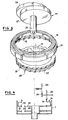
- FIG. 4 clearly shows the relative positions of the various annular members one inside the other and maintains them by simple contact with each other.
- the annular satellite 20 is introduced inside the case so as to rest on the bottom 3 of the latter, then the sun gear is introduced in its turn and placed on the shoulder 12.
- the also axial introduction of the eccentric 24 so that the control axis 26 slides in the extension 2 of the housing pushes the satellite 20 laterally and forces the lower 22 and upper 18 teeth to engage respectively with the teeth 10 of the housing and with the teeth 15 of the sun gear 14.
- the upper disc 28 of the eccentric 24 presses on the satellite 20 and blocks it axially.
- the plate 4 carrying the counting members as well as the star pinion 34 and the drive pinion 30 can then be introduced into the housing 1 so as to put the pinion 30 in engagement with the spiral toothing 16.
- the production of the various components constituted solely by planetary or satellite rings is much easier than that of the organs of the worm or similar type, used previously.
- the teeth do not have sharp edges, but a curved profile facilitating their sliding on the opposite teeth.
- the counter thus produced also includes a speed indicator device.
- the eccentric 24 is hollowed out in its central part to form an annular housing 42 around a central pin 44.
- a magnetic disc 46 pierced with an axial hole for nesting on the pin 44.
- the diameter of the disc 46 is less than that of the housing 42 so that, in the space between them, can penetrate the side skirt of a bell 48 secured to a vertical axis 49 supporting a indicator needle (not shown) which is fixed in the plate 4, and returned by a spiral spring 50.
- the magnetic disc 46 is thus driven at the same time as the eccentric 24 by the control cable fixed on the axis 26. It transmits this movement at bell 48 and therefore the speed indicator hand.
- the counter thus produced can, in the same manner as above, be mounted by a simple stacking of the various members inside the housing.
- the size of the reduction mechanism is limited to the height of the sun gear above the bottom 3 of the housing, that is to say practically the superposition of the three fixed teeth 10 and mobile 15 and 16, the others organs and in particular the satellite and the eccentric, possibly with the magnetic disc and the bell, being placed inside this space.
Description
Il est bien connu que les compteurs kilométriques destinés aux véhicules à deux roues ou analogues doivent non seulement être robustes mais également avoir des dimensions le plus faible possible et un couple élevé.It is well known that the odometers intended for two-wheeled vehicles or the like must not only be robust but also have the smallest possible dimensions and a high torque.
Les compteurs habituellement utilisés comportent à l'intérieur d'un boîtier prolongé par une entrée de câble de commande un système indicateur totalisateur et un mécanisme de démultiplication interposé entre ce système et un axe rotatif solidaire du câble de commande. Afin de permettre une démultiplication suffisamment importante et suffisamment précise, le mécanisme de démultiplication comporte des renvois d'angle par vis sans fin.The meters usually used have, inside a housing extended by a control cable entry, a totalizing indicator system and a reduction mechanism interposed between this system and a rotary axis integral with the control cable. In order to allow a sufficiently large and sufficiently precise reduction, the reduction mechanism includes angle references by worm.
La démultiplication obtenue est satisfaisante. Toutefois, la fabrication des vis sans fin est délicate et leur montage doit être effectué avec précision.The reduction obtained is satisfactory. However, the production of worms is delicate and their assembly must be carried out with precision.
La présente invention a donc pour but de rendre plus simples la réalisation et le montage du mécanisme de démultiplication tout en réduisant son encombrement.The present invention therefore aims to make it simpler to produce and assemble the reduction mechanism while reducing its size.
Cette invention a en effet pour objet un compteur kilométrique dont le mécanisme de démultiplication comporte un satellite excentré portant deux dentures extérieures, coaxiales et superposées, ayant, des nombres de dents différents, qui sont en prise l'une avec une denture fixe et l'autre avec un planétaire libre en rotation, un excentrique solidaire de l'axe de liaison au câble de commande qui entraîne le satellite pour provoquer la rotation du planétaire, ce dernier comportant à sa partie supérieure une denture spirale axiale d'entraînement du système totalisateur indicateur.The object of this invention is in fact an odometer, the reduction mechanism of which comprises an eccentric satellite carrying two external teeth, coaxial and superimposed, having, different numbers of teeth, which are engaged one with a fixed teeth and the other with a free planetary in rotation, an eccentric integral with the axis of connection to the control cable which drives the satellite to cause the rotation of the planetary, the latter comprising at its upper part an axial spiral toothing driving the totalizing indicator system .
Dans un tel mécanisme les différents organes: satellite, denture fixe ou planétaire, par exemple, sont constitués par des couronnes de faible hauteur axiale qui sont simplement disposées les unes au-dessus des autres ou les unes à l'intérieur des autres et doivent simplement être disposées de façon à être mises en contact sans précision particulière.In such a mechanism, the various organs: satellite, fixed or planetary toothing, for example, consist of crowns of small axial height which are simply placed one above the other or one inside the other and must simply be arranged so as to be brought into contact without particular precision.
Selon un mode de réalisation particulier, le compteur objet de l'invention comporte également un tachymètre magnétique, l'excentrique comportant un évidement central de logement d'un disque aimanté et d'une cloche solidaire d'une aiguille indicatrice.According to a particular embodiment, the meter object of the invention also includes a magnetic tachometer, the eccentric comprising a central recess for housing a magnetic disc and a bell secured to an indicator needle.
La description ci-dessous d'un mode de réalisation donné à titre d'exemple non limitatif fera d'ailleurs ressortir les avantages et caractéristiques de l'invention. Sur les dessins:
- la Fig. 1 est une vue en coupe axiale d'un compteur suivant l'invention;
- la Fig. 2 est une vue de dessus du boîtier de ce compteur;
- la Fig. 3 est une vue éclatée montrant les organes du mécanisme de démultiplication avant leur introduction dans le boîtier;
- la Fig. 4 est un schéma de la chaîne cinématique du mécanisme de démultiplication.
- Fig. 1 is an axial section view of a counter according to the invention;
- Fig. 2 is a top view of the housing of this counter;
- Fig. 3 is an exploded view showing the members of the reduction mechanism before their introduction into the housing;
- Fig. 4 is a diagram of the kinematic chain of the reduction mechanism.
Le compteur représenté sur la Fig. 1 comporte un boîtier 1 qui est prolongé à l'une de ses extrémités par une entrée de câble de commande 2. A son extrémité opposée le boîtier 1 est fermé par une platine 4 qui comporte d'une part une plaque 5 percée d'une fenêtre de lecture et d'autre part des ailes 6 de support d'organes de comptage 8. La paroi latérale du boîtier 1 comporte au niveau du fond 3 une denture interne circulaire 10 et, légèrement au-dessus de cette denture, un épaulement interne 12 qui délimite un logement pour un planétaire annulaire 14. Comme le montre plus particulièrement la Fig. 3, le planétaire 14 comporte d'une part une couronne dentée intérieurement 15 et d'autre part, à sa partie supérieure, une denture en spirale 16 dont les dents sont dirigées axialement.The counter shown in FIG. 1 comprises a
Le planétaire 14 est libre en rotation à l'intérieur du boîtier cylindrique 1 sur l'épaulement 12. Sa denture interne 15 est toutefois en prise avec la denture supérieure 18 d'un satellite 20 monté de manière excentrée dans le boîtier 1. Le satellite 20 tourne sur le fond 3 du boîtier cylindrique et comporte une seconde denture extérieure 22 qui est en prise avec la denture interne 10 du boîtier. Les deux dentures extérieures 18 et 22 sont ainsi coaxiales et superposées bien que séparées par une distance qui correspond sensiblement à la distance entre la denture interne 10 du boîtier et la couronne dentée intérieurement 15 du planétaire. Les dentures 18 et 22 du satellite 20 ont toutefois des nombres de dents différents, la denture inférieure 22 ayant en outre un nombre de dents inférieur à celui de la denture interne 10 du boîtier, tandis que la denture supérieure 18 a un nombre de dents analogue à celui de la couronne interne 15 du planétaire. Par exemple, la denture interne du boîtier comporte vingt-et-une dents, tandis que la denture inférieure 22 du satellite n'en comporte que dix-neuf, la denture supérieure du satellite de même que la couronne du planétaire comportant vingt dents.The
La surface interne 21 du satellite annulaire 20 est par ailleurs en contact avec un excentrique 24 qui est solidaire d'un axe 26 logé dans le prolongement 2 du boîtier 1 et destiné à être raccordé au câble de commande et à tourner avec ce dernier. L'excentrique 24 comporte de préférence deux disques circulaires décalés de 180° et fixés sur le même axe 24 de manière que la distance maximale entre le centre de cet axe et leur bord périphérique correspondent au diamètre interne du satellite 20. Le disque inférieur 27 a en outre une épaisseur axiale analogue à celle du satellite 20. Par suite, ce disque inférieur 27 est toujours en contact en un point avec le satellite 20 tandis que le disque supérieur 28 appuie en un point opposé sur le satellite et le maintient en position à l'intérieur du boîtier (Fig. 1 ).The
Lors de la rotation du câble de commande l'axe 26 et l'excentrique 24 sont également entraînés en rotation. Le disque inférieur 27 de l'excentrique 24 repousse alternativement le satellite 20 dans deux directions opposées au cours de chacune de ses rotations et le déplace ainsi dent à dent autour de la denture interne fixe 10 du boîtier. Comme la denture supérieure 18 du satellite a un nombre de dents différent, elle provoque le déplacement du planétaire 14 d'une distance qui est fonction de cette différence, et par suite celui de la denture spirale 16 de la partie supérieure de ce planétaire.During the rotation of the control cable the
La denture spirale 16 forme un renvoi d'angle avec un pignon 30 qui est monté libre en rotation sur un axe 32 porté par les deux ailes opposées 6 de la platine 4. Le nombre des dents du pignon 30 est de préférence égal à celui des dents spirales de la denture 16 mais, par contre, cette denture spirale 16 comporte un nombre de dents nettement inférieur à celui de la couronne dentée 15 du même planétaire. Par exemple, la douronne dentée 15 comporte vingt dents, tandis que la denture spirale 16 et le pignon 30 en comportent treize.The spiral toothing 16 forms an angular gear with a
La rotation du pignon denté 30 est transmise aux organes de comptage car ce pignon 30 est solidaire d'un pignon étoile 34 en prise avec les crans latéraux 35 de la première d'une série de roues graduées 36. Toutes les roues graduées 36 sont libres en rotation sur un même axe 38 porté par les deux ailes 6 de la platine 4 et comportent des crans 35 en prise avec un pignon étoile 39 libre en rotation sur l'axe 32. Par ailleurs, les roues graduées 36 à l'exception de la dernière comportent un toc latéral 40 d'entraînement du pignon étoile 39 en prise avec la roue suivante. De cette manière, chaque roue 36 provoque le déplacement de la roue suivante d'une graduation à chacun de ses tours tandis que le déplacement de la première roue 36 est fonction de la vitesse de rotation du câble de commande et du rapport du mécanisme de démultiplication. Il est clair que ce rapport peut varier en fonction du nombre de dents des différents organes et notamment des dentures du planétaire et/ou du satellite. Ceci apparaît plus clairement sur le schéma de la Fig. 4 qui montre la chaîne cinématique du mécannisme de démultiplication entraînant la première roue graduée 36.The rotation of the
Cette Fig. 4, comme d'ailleurs la Fig. 1, fait apparaître clairement les positions relatives des différents organes annulaires les uns à l'intérieur des autres et leur maintient par simple contact les uns avec les autres. En effet, lors de l'assemblage du compteur, le satellite annulaire 20 est introduit à l'intérieur du boîtier de façon à reposer sur le fond 3 de celui-ci, puis le planétaire est introduit à son tour et placé sur l'épaulement 12. L'introduction également axiale de l'excentrique 24 de manière que l'axe de commande 26 glisse dans le prolongement 2 du boîtier repousse le satellite 20 latéralement et oblige les dentures inférieure 22 et supérieure 18 à entrer en prise respectivement avec la denture 10 du boîtier et avec la denture 15 du planétaire 14. En même temps, le disque supérieur 28 de l'excentrique 24 appuie sur le satellite 20 et le bloque axialement. La platine 4 portant les organes de comptage ainsi que le pignon étoile 34 et le pignon d'entraînement 30, peut alors être introduite dans le boîtier 1 de façon à mettre le pignon 30 en prise avec la denture spirale 16. Aucune précision de centrage nést nécessaire puisque les positions angulaires relatives initiales des différents organes n'ont pas d'importance. Leur déplacement angulaire sous l'effet de la rotation du câble de commande sera le même quelles que soient les dents des organes qui sont primitivement en contact. Le montage du compteur est par suite extrêmement simple.This Fig. 4, as moreover FIG. 1, clearly shows the relative positions of the various annular members one inside the other and maintains them by simple contact with each other. Indeed, during the assembly of the counter, the
En outre, la réalisation des différents composants constitués uniquement par des couronnes planétaires ou satellites est nettement plus facile que celle des organes du type vis sans fin ou analogue, utilisés antérieurement. De préférence d'ailleurs, les dents ne présentent pas d'arêtes vives, mais un profil incurvé facilitant leur glissement sur la denture opposée.In addition, the production of the various components constituted solely by planetary or satellite rings is much easier than that of the organs of the worm or similar type, used previously. Preferably, moreover, the teeth do not have sharp edges, but a curved profile facilitating their sliding on the opposite teeth.
De préférence, le compteur ainsi réalisé comporte également un dispositif indicateur de vitesse. Dans ce but, l'excentrique 24 est évidé dans sa partie centrale pour former un logement annulaire 42 autour d'un pion central 44. Dans le logement 42 est monté un disque aimanté 46 percé d'un trou axial d'emboîtement sur le pion 44. Le diamètre du disque 46 est inférieur à celui du logement 42 de sorte que, dans l'espace entre eux, peut pénétrer la jupe latérale d'une cloche 48 solidaire d'un axe vertical 49 de support d'une aiguille indicatrice (non représentée) qui est fixée dans la platine 4, et rappelée par un ressort spirale 50. Le disque aimanté 46 est ainsi entraîné en même temps que l'excentrique 24 par le câble de commande fixé sur l'axe 26. Il transmet ce mouvement à la cloche 48 et par suite à l'aiguille indicatrice de vitesse.Preferably, the counter thus produced also includes a speed indicator device. For this purpose, the eccentric 24 is hollowed out in its central part to form an
Le compteur ainsi réalisé peut, de la même manière que précédemment, être monté par un simple empilage des différents organes à l'intérieur du boîtier. En outre, l'encombrement du mécanisme de démultiplication se limite à la hauteur du planétaire au-dessus du fond 3 du boîtier, c'est-à-dire pratiquement à la superposition des trois dentures fixe 10 et mobiles 15 et 16, les autres organes et notamment le satellite et l'excentrique, avec éventuellement le disque aimanté et la cloche, étant placés à l'intérieur de cet espace. Il en résulte un compteur de dimensions nettement plus réduites que les compteurs habituels, qui présente en outre l'avantage de pouvoir être monté facilement sans exigences particulières de précision.The counter thus produced can, in the same manner as above, be mounted by a simple stacking of the various members inside the housing. In addition, the size of the reduction mechanism is limited to the height of the sun gear above the
Claims (9)
Applications Claiming Priority (2)
| Application Number | Priority Date | Filing Date | Title |
|---|---|---|---|
| FR8107997 | 1981-04-22 | ||
| FR8107997A FR2504707A1 (en) | 1981-04-22 | 1981-04-22 | KILOMETER COUNTER WITH PLANETARY DEMULTIPLICATION MECHANISM FOR TWO-WHEELED VEHICLE OR THE LIKE |
Publications (2)
| Publication Number | Publication Date |
|---|---|
| EP0063984A1 EP0063984A1 (en) | 1982-11-03 |
| EP0063984B1 true EP0063984B1 (en) | 1985-01-23 |
Family
ID=9257656
Family Applications (1)
| Application Number | Title | Priority Date | Filing Date |
|---|---|---|---|
| EP82400641A Expired EP0063984B1 (en) | 1981-04-22 | 1982-04-07 | Odometer with planetary gear reduction mechanism for a two-wheeled vehicle or the like |
Country Status (5)
| Country | Link |
|---|---|
| US (1) | US4431910A (en) |
| EP (1) | EP0063984B1 (en) |
| JP (1) | JPS57204353A (en) |
| DE (1) | DE3262012D1 (en) |
| FR (1) | FR2504707A1 (en) |
Family Cites Families (5)
| Publication number | Priority date | Publication date | Assignee | Title |
|---|---|---|---|---|
| FR471890A (en) * | 1914-05-06 | 1914-11-13 | Norton Harding Van Sicklen | Improvements made to devices that can be used as odometers, revolution counters, etc. |
| FR1341951A (en) * | 1962-12-22 | 1963-11-02 | Borletti Spa | Improvements to kilometer-counter tachometers, particularly for motor vehicles |
| US3812331A (en) * | 1972-12-05 | 1974-05-21 | Ford Motor Co | Transmission mounted speed sensor with odometer switch |
| US4354097A (en) * | 1978-07-20 | 1982-10-12 | Societe Internationale De Mecanique Industrielle S.A. | Odometers |
| US4350880A (en) * | 1980-10-08 | 1982-09-21 | Quintilian Bartholomew F | Automatic fuel-cost monitoring system |
-
1981
- 1981-04-22 FR FR8107997A patent/FR2504707A1/en active Granted
-
1982
- 1982-04-07 EP EP82400641A patent/EP0063984B1/en not_active Expired
- 1982-04-07 DE DE8282400641T patent/DE3262012D1/en not_active Expired
- 1982-04-12 US US06/367,745 patent/US4431910A/en not_active Expired - Fee Related
- 1982-04-20 JP JP57065996A patent/JPS57204353A/en active Pending
Also Published As
| Publication number | Publication date |
|---|---|
| DE3262012D1 (en) | 1985-03-07 |
| FR2504707A1 (en) | 1982-10-29 |
| EP0063984A1 (en) | 1982-11-03 |
| US4431910A (en) | 1984-02-14 |
| FR2504707B1 (en) | 1983-07-22 |
| JPS57204353A (en) | 1982-12-15 |
Similar Documents
| Publication | Publication Date | Title |
|---|---|---|
| EP0663717B1 (en) | Magnetic coupling system for driving two rotating elements and fluid meter comprising such a system | |
| EP0484194A1 (en) | Detector of angle of rotation | |
| FR2568484A1 (en) | DEVICE FOR DISPLAYING THE DEGREE OF CLAMPS OF ASPIRE AIR FILTERS | |
| WO2021001570A1 (en) | Transformable wheel suitable for climbing stairs and autonomous robot equipped with at least one such wheel | |
| EP0063984B1 (en) | Odometer with planetary gear reduction mechanism for a two-wheeled vehicle or the like | |
| EP2313812A1 (en) | Movement for a timepiece with an onboard automatic winding device | |
| EP2919077A2 (en) | Device for driving an analogue indicator, in particular a date ring | |
| CH519742A (en) | Timer mechanism for timepiece | |
| FR2783483A1 (en) | ANGLE SENSOR SYSTEM, IN PARTICULAR FOR A MOTOR VEHICLE STEERING COLUMN | |
| FR2790552A1 (en) | Indicator for speed and/or engine revolution instruments on a vehicles instrument panel | |
| FR2706690A1 (en) | Rotating electrical contactor. | |
| EP0060156B1 (en) | Counter for two-wheel vehicle or similar vehicle | |
| EP0834426B1 (en) | Assembly for top of steering column defining an assembly position for the steering wheel | |
| FR2472867A1 (en) | ELECTRIC MOTOR WITH STEPPING ADVANCE AND MOTOREDUCTING ASSEMBLY EMPLOYING THE SAME | |
| EP0363245B1 (en) | Device for the control of the angular position of a member entraining a rotating drive shaft | |
| EP0753431A1 (en) | Device for storing objects, in particular in motor vehicles | |
| FR2709795A1 (en) | Non-permanent drive device for transmission reduction mechanism | |
| FR3089587A1 (en) | REDUCER FOR A THERMAL ENGINE STARTER | |
| CH297476A (en) | Automatic watch winding mechanism. | |
| EP0094857A1 (en) | Sensor apparatus, especially for driving a cycle odometer | |
| FR2778759A1 (en) | TIME INDICATION DEVICE FOR MULTIPLE TIME ZONES | |
| CH380474A (en) | Device for driving in one direction or the other of a driven shaft from a driving shaft rotating in a determined direction | |
| CH715245A2 (en) | Display device comprising a movable indicator moving along a slide. | |
| EP0813756A1 (en) | Improved rotary electrical contactor | |
| FR2701143A1 (en) | Device for remote reading of fluid consumption recorded by a meter |
Legal Events
| Date | Code | Title | Description |
|---|---|---|---|
| PUAI | Public reference made under article 153(3) epc to a published international application that has entered the european phase |
Free format text: ORIGINAL CODE: 0009012 |
|
| AK | Designated contracting states |
Designated state(s): BE DE GB IT LU NL |
|
| 17P | Request for examination filed |
Effective date: 19830405 |
|
| ITF | It: translation for a ep patent filed |
Owner name: BARZANO' E ZANARDO MILANO S.P.A. |
|
| GRAA | (expected) grant |
Free format text: ORIGINAL CODE: 0009210 |
|
| AK | Designated contracting states |
Designated state(s): BE DE GB IT LU NL |
|
| REF | Corresponds to: |
Ref document number: 3262012 Country of ref document: DE Date of ref document: 19850307 |
|
| PG25 | Lapsed in a contracting state [announced via postgrant information from national office to epo] |
Ref country code: LU Free format text: LAPSE BECAUSE OF NON-PAYMENT OF DUE FEES Effective date: 19850430 |
|
| PLBE | No opposition filed within time limit |
Free format text: ORIGINAL CODE: 0009261 |
|
| STAA | Information on the status of an ep patent application or granted ep patent |
Free format text: STATUS: NO OPPOSITION FILED WITHIN TIME LIMIT |
|
| 26N | No opposition filed | ||
| PGFP | Annual fee paid to national office [announced via postgrant information from national office to epo] |
Ref country code: LU Payment date: 19900320 Year of fee payment: 9 |
|
| PGFP | Annual fee paid to national office [announced via postgrant information from national office to epo] |
Ref country code: DE Payment date: 19900323 Year of fee payment: 9 |
|
| PGFP | Annual fee paid to national office [announced via postgrant information from national office to epo] |
Ref country code: GB Payment date: 19900402 Year of fee payment: 9 |
|
| ITTA | It: last paid annual fee | ||
| PGFP | Annual fee paid to national office [announced via postgrant information from national office to epo] |
Ref country code: NL Payment date: 19900430 Year of fee payment: 9 |
|
| PGFP | Annual fee paid to national office [announced via postgrant information from national office to epo] |
Ref country code: BE Payment date: 19900515 Year of fee payment: 9 |
|
| PG25 | Lapsed in a contracting state [announced via postgrant information from national office to epo] |
Ref country code: GB Effective date: 19910407 |
|
| PG25 | Lapsed in a contracting state [announced via postgrant information from national office to epo] |
Ref country code: BE Effective date: 19910430 |
|
| BERE | Be: lapsed |
Owner name: HURET ET SES FILS Effective date: 19910430 |
|
| PG25 | Lapsed in a contracting state [announced via postgrant information from national office to epo] |
Ref country code: NL Effective date: 19911101 |
|
| GBPC | Gb: european patent ceased through non-payment of renewal fee | ||
| NLV4 | Nl: lapsed or anulled due to non-payment of the annual fee | ||
| PG25 | Lapsed in a contracting state [announced via postgrant information from national office to epo] |
Ref country code: DE Effective date: 19920201 |