EP0063487A2 - Electromagnetic relay - Google Patents
Electromagnetic relay Download PDFInfo
- Publication number
- EP0063487A2 EP0063487A2 EP82301984A EP82301984A EP0063487A2 EP 0063487 A2 EP0063487 A2 EP 0063487A2 EP 82301984 A EP82301984 A EP 82301984A EP 82301984 A EP82301984 A EP 82301984A EP 0063487 A2 EP0063487 A2 EP 0063487A2
- Authority
- EP
- European Patent Office
- Prior art keywords
- spring
- electromagnetic relay
- restoring spring
- base block
- protrusion
- Prior art date
- Legal status (The legal status is an assumption and is not a legal conclusion. Google has not performed a legal analysis and makes no representation as to the accuracy of the status listed.)
- Granted
Links
Images


Classifications
-
- H—ELECTRICITY
- H01—ELECTRIC ELEMENTS
- H01H—ELECTRIC SWITCHES; RELAYS; SELECTORS; EMERGENCY PROTECTIVE DEVICES
- H01H50/00—Details of electromagnetic relays
- H01H50/54—Contact arrangements
- H01H50/56—Contact spring sets
-
- H—ELECTRICITY
- H01—ELECTRIC ELEMENTS
- H01H—ELECTRIC SWITCHES; RELAYS; SELECTORS; EMERGENCY PROTECTIVE DEVICES
- H01H50/00—Details of electromagnetic relays
- H01H50/02—Bases; Casings; Covers
- H01H50/04—Mounting complete relay or separate parts of relay on a base or inside a case
- H01H50/041—Details concerning assembly of relays
- H01H50/042—Different parts are assembled by insertion without extra mounting facilities like screws, in an isolated mounting part, e.g. stack mounting on a coil-support
-
- H—ELECTRICITY
- H01—ELECTRIC ELEMENTS
- H01H—ELECTRIC SWITCHES; RELAYS; SELECTORS; EMERGENCY PROTECTIVE DEVICES
- H01H50/00—Details of electromagnetic relays
- H01H50/64—Driving arrangements between movable part of magnetic circuit and contact
- H01H50/641—Driving arrangements between movable part of magnetic circuit and contact intermediate part performing a rectilinear movement
- H01H50/642—Driving arrangements between movable part of magnetic circuit and contact intermediate part performing a rectilinear movement intermediate part being generally a slide plate, e.g. a card
Definitions
- the present invention relates to an electromagnetic relay, particularly to the structure for the fixing of a spring member of the electromagnetic relay to the base block of the housing of the electromagnetic relay.
- the electromagnetic relay of the present invention is of a small size, for example 32 x 35 x 32 mm, wherein an assembly of elements of the electromagnetic relay, such as an electromagnet, an armature, a card, a movable contact carried on a movable contact spring, a fixed contact carried on a fixed contact spring, and a restoring spring, is encased in a housing formed by a plastic base block and a plastic cover.
- elements of the electromagnetic relay such as an electromagnet, an armature, a card, a movable contact carried on a movable contact spring, a fixed contact carried on a fixed contact spring, and a restoring spring
- FIG. 1 A prior art structure for fixing one of the springs of the electromagnetic relay, for example, the restoring spring, to the base block is illustrated in Fig. 1.
- the electromagnetic relay of Fig. 1 comprises a plastic base block 1', a restoring spring 2', a movable contact spring 3', a fixed contact spring 4', a card 5', an armature 6' and an electromagnet 7'.
- the electromagnet 7' comprises a core 73', a bobbin 72', a coil 71' and a yoke 74'.
- the two terminal conductors (not shown) of the coil 71', the terminal conductor 32' of the movable contact spring 3', and the terminal conductor 42' of the fixed contact spring 4' penetrate through the corresponding apertures of the base block 1' so that the structure of the electromagnet is coupled to the base block 1'. Also, in order to ensure the fixing of the restoring spring 2' to the base block 1', one end of the restoring spring 2' is pressed into a slot 111'in a rectangular corner protrusion 11' of the base block 1'.
- the thickness of the restoring spring 2' cannot be thicker than a predetermined thickness, due to the design requirements of the electromagnetic relay, while the gap length of the slot 111 * cannot be smaller than a predetermined length due to the plastic moulding process requirements.
- a restoring spring is constructed in which the thickness of the end portion corresponding to the slot of the corner protrusion is larger than the thickness of the rest of the restoring spring or in which a depression is formed by a shock--pressing process near the end portion of the restoring spring corresponding to the slot of the corner protrusion causing the effective thickness of the end portion to be increased, so as to make the thickness of the end portion of the restoring spring match the width of the gap of the slot in the corner protrusion.
- the object of the present invention is to provide an improved structure of the electromagnetic relay of the type described above, wherein the above described problem is solved and a satisfactorily firm fixing between an element of the electromagnetic relay and the base block of the housing is. achieved, so that a satisfactory structure and a reliable operation of an electromagnetic relay are ensured.
- an electromagnetic relay comprising a base block, an electromagnet, an armature, a card and a plurality of spring means, wherein a spring-supporting protrusion is formed on a predetermined portion of the base block and a slot is formed in the protrusion, characterised in that a plurality of side projections are formed in a portion of at least one of the spring means, and the portion of the spring means having the plurality of side projections is inserted into the slot of the protrusion in such a manner that the side projections are inserted into deep holes adjoining slot.
- FIG. 2 The structure of an electromagnetic relay in accordance with an embodiment of the present invention is illustrated in Figs. 2 through 8.
- a perspective view of the electromagnetic relay is illustrated in Fig. 2.
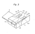
- a perspective view of the important portion of Fig. 2 is illustrated in Fig. 3.
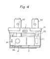
- the detailed structure of the electromagnetic relay of Fig. 2 is illustrated in Figs. 4, 5, 6, 7A, 7B . and 8.
- the electromagnetic relay of Fig. 2 comprises a plastic base block 1, a restoring spring 2, a movable contact spring 3, a fixed contact spring 4, a card 5, and armature 6 and an electromagnet 7.
- the electromagnet 7 comprises a core 73, a bobbin 72, a coil 71 and a yoke 74.
- the fixed contact spring 4, the movable contact spring terminal 32 and the two terminal conductors of the coil 71 penetrate through the apertures 12, 13, 14 and 15, respectively.
- the assembly of the electromagnet 7, the armature 6, the card 5, the fixed contact spring 4, the movable contact spring 3 and the restoring spring 2 is encased in a housing consisting of the base block 1 and a cover (not shown).
- the restoring spring 2 is fixed at its right end to a corner protrusion 11 of the base block 1, as illustrated in Figs. 2, 3, 4 and 5.
- the fixing structure will be described with reference to Figs. 6, 7A, 7B and 8.
- the corner protrusion 11 of the base block 1 has a horizontal slot 111 in the direction parallel with the surface of the restoring spring 2. At the bottom of the horizontal slot 111, there are provided a plurality of deep holes llla, lllb. Between these deep holes llla and lllb, a cubic column 111m is formed.
- the restoring spring 2 has, in general, a rectangular shape, except that towards one end thereof a plurality of side projections 21 and 22 is provided.
- the width w a of the deep hole llla illustrated in Fig. 7A is a little less than the width w b of each of the side projections 21, 22.
- the restoring spring 2 is provided at one end, opposite to that on which the projections are located with a rectangular hole 24 into which the upper end of the card 5 is fitted.
- a downward depression 25 of the restoring spring 2 is provided, said depression 25 being formed by a shock--pressing process or the like.
- the restoring spring 2 may be provided with a circular hole 26, shown in broken lines, through which the upper portion of the fixed contact spring 4 is allowed to penetrate. It is possible to provide depressions 211 and 221 in the side projections 21, 22, said depressions 211 and 221 being formed by a shock--pressing process or the like.
- the fixing of the restoring spring 2 to the rectangular corner protrusion 11 of the base block 1 is carried out by inserting one end of the restoring spring 2 into the slot 111 of the corner protrusion 11.
- the side projections 21 and 22 are inserted into the deep holes llla and lllb, respectively.
- the top of the cubic column lllm abuts against the side edge portion 23 of the restoring spring 2 between the side projections 21 and 22.
- the end portion of the restoring spring 2 including the side projections 21 and 22 is firmly fixed to the corner protrusion 11 of the base block 1, as illustrated in Figures 2, 3 and 6.
Abstract
Description
- The present invention relates to an electromagnetic relay, particularly to the structure for the fixing of a spring member of the electromagnetic relay to the base block of the housing of the electromagnetic relay.
- The electromagnetic relay of the present invention is of a small size, for example 32 x 35 x 32 mm, wherein an assembly of elements of the electromagnetic relay, such as an electromagnet, an armature, a card, a movable contact carried on a movable contact spring, a fixed contact carried on a fixed contact spring, and a restoring spring, is encased in a housing formed by a plastic base block and a plastic cover.
- A prior art structure for fixing one of the springs of the electromagnetic relay, for example, the restoring spring, to the base block is illustrated in Fig. 1. The electromagnetic relay of Fig. 1 comprises a plastic base block 1', a restoring spring 2', a movable contact spring 3', a fixed contact spring 4', a card 5', an armature 6' and an electromagnet 7'. The electromagnet 7' comprises a core 73', a bobbin 72', a coil 71' and a yoke 74'.
- The two terminal conductors (not shown) of the coil 71', the terminal conductor 32' of the movable contact spring 3', and the terminal conductor 42' of the fixed contact spring 4' penetrate through the corresponding apertures of the base block 1' so that the structure of the electromagnet is coupled to the base block 1'. Also, in order to ensure the fixing of the restoring spring 2' to the base block 1', one end of the restoring spring 2' is pressed into a slot 111'in a rectangular corner protrusion 11' of the base block 1'.
- However, in the prior art structure of Fig. 1, there is a problem in that the restoring spring 2' is not sufficiently firmly fixed to the corner protrusion 11', because such a mere pressing of the restoring spring 2' into the slot 111' cannot achieve a firm holding of the restoring spring 2' by the corner protrusion 11'. This is because, when the restoring spring 2' is subjected to frequent spring action or is subjected to vibrations, the restoring spring inevitably becomes loosened from the corner protrusion 111'.
- In the structure of Fig. 1, the thickness of the restoring spring 2' cannot be thicker than a predetermined thickness, due to the design requirements of the electromagnetic relay, while the gap length of the slot 111* cannot be smaller than a predetermined length due to the plastic moulding process requirements. Under these circumstances, in the prior art structure, a restoring spring is constructed in which the thickness of the end portion corresponding to the slot of the corner protrusion is larger than the thickness of the rest of the restoring spring or in which a depression is formed by a shock--pressing process near the end portion of the restoring spring corresponding to the slot of the corner protrusion causing the effective thickness of the end portion to be increased, so as to make the thickness of the end portion of the restoring spring match the width of the gap of the slot in the corner protrusion.
- However, there is also another problem in that the manufacture of such a restoring spring, consisting of portions having different thicknesses, increases the cost of the production of the device and in that the fixing of the restoring spring, having such a depression in the end portion, to the slot of the corner protrusion does not provide a completely firm fixing there between. 4
- The object of the present invention is to provide an improved structure of the electromagnetic relay of the type described above, wherein the above described problem is solved and a satisfactorily firm fixing between an element of the electromagnetic relay and the base block of the housing is. achieved, so that a satisfactory structure and a reliable operation of an electromagnetic relay are ensured.
- According to the present invention, there is provided an electromagnetic relay comprising a base block, an electromagnet, an armature, a card and a plurality of spring means, wherein a spring-supporting protrusion is formed on a predetermined portion of the base block and a slot is formed in the protrusion, characterised in that a plurality of side projections are formed in a portion of at least one of the spring means, and the portion of the spring means having the plurality of side projections is inserted into the slot of the protrusion in such a manner that the side projections are inserted into deep holes adjoining slot.
- The invention will now be described in more detail, solely by way of example, with reference to the accompanying drawings, in which:-
- Figure 1 illustrates a structure of a prior art electromagnetic relay;
- Figure 2 illustrates a perspective view of the structure of an electromagnetic relay according to an embodiment of the present invention;
- Figure 3 illustrates an enlarged view of the fixing structure in the device of Figure 2;
- Figure 4 illustrates the top view of the device of Figure 2;
- Figure 5 illustrates the front view of the device of Figure 2;
- Figure 6 illustrates the top view of the fixing structure of Figure 3;
- Figures 7A and 7B illustrate, respectively, the top views of the structure of the base block and the restoring spring for the fixing structure of Figure 6; and
- Figure 8 illustrates the front view of the base block with the assembly of the electromagnetic of the electromagnetic relay being removed.
- The structure of an electromagnetic relay in accordance with an embodiment of the present invention is illustrated in Figs. 2 through 8. A perspective view of the electromagnetic relay is illustrated in Fig. 2. A perspective view of the important portion of Fig. 2 is illustrated in Fig. 3. The detailed structure of the electromagnetic relay of Fig. 2 is illustrated in Figs. 4, 5, 6, 7A, 7B.and 8.
- The electromagnetic relay of Fig. 2 comprises a plastic base block 1, a
restoring spring 2, amovable contact spring 3, afixed contact spring 4, acard 5, andarmature 6 and anelectromagnet 7. Theelectromagnet 7 comprises acore 73, abobbin 72, acoil 71 and ayoke 74. The fixedcontact spring 4, the movablecontact spring terminal 32 and the two terminal conductors of thecoil 71 penetrate through theapertures electromagnet 7, thearmature 6, thecard 5, thefixed contact spring 4, themovable contact spring 3 and therestoring spring 2 is encased in a housing consisting of the base block 1 and a cover (not shown). - When the
coil 71 of theelectromagnet 7 is energized, the lower portion of thearmature 6 is attracted by thecore 73 to effect a pivoted motion of thearmature 6, and hence the upper portion of thearmature 6 pushes thecard 5 upwardly. The free end of themovable contact spring 3 is pushed upwardly by the upward motion of thecard 5 to cause the fixed contact 41 to come in contact with the movable contact 31. At the same time, the left end of the restoringspring 2 connected to thecard 5 is pushed upwardly by the upward motion of thecard 5 against the resilient force of the restoringspring 2. - When the
coil 71 of theelectromagnet 7 is deenergized, the resilient force of the restoringspring 2 causes thecard 5 to move downward, and hence the free end of themovable contact spring 3 is pushed downward by the downward motion of thecard 5 to cause the movable contact 31 to become disengaged from the fixed contact 41. - The restoring
spring 2 is fixed at its right end to a
corner protrusion 11 of the base block 1, as illustrated in Figs. 2, 3, 4 and 5. The fixing structure will be described with reference to Figs. 6, 7A, 7B and 8. - The
corner protrusion 11 of the base block 1 has a horizontal slot 111 in the direction parallel with the surface of therestoring spring 2. At the bottom of the horizontal slot 111, there are provided a plurality of deep holes llla, lllb. Between these deep holes llla and lllb, a cubic column 111m is formed. - The restoring
spring 2 has, in general, a rectangular shape, except that towards one end thereof a plurality ofside projections side projections spring 2 is provided at one end, opposite to that on which the projections are located with arectangular hole 24 into which the upper end of thecard 5 is fitted. At the end portion where theside projections downward depression 25 of the restoringspring 2 is provided, saiddepression 25 being formed by a shock--pressing process or the like. The restoringspring 2 may be provided with acircular hole 26, shown in broken lines, through which the upper portion of the fixedcontact spring 4 is allowed to penetrate. It is possible to providedepressions side projections depressions - The fixing of the
restoring spring 2 to therectangular corner protrusion 11 of the base block 1 is carried out by inserting one end of the restoringspring 2 into the slot 111 of thecorner protrusion 11. When the end portion of therestoring spring 2 is inserted into the slot 111 of thecorner protrusion 11, theside projections restoring spring 2 between theside projections restoring spring 2, including theside projections corner protrusion 11 of the base block 1, as illustrated in Figures 2, 3 and 6. - According to the fixing structure illustrated in Figures 2, 3 and 6, even when the restoring
spring 2 is frequently subjected to a spring action and vibrations, the
corner protrusion 11- and the restoringspring 2 remain firmly fixed, so that no loosening of the restoringspring 2 from thecorner protrusion 11 takes place. - It will be observed from Figures 2 to 8 that the external shape of the
protrusion 11 of the preferred embodiment is that of a rectangular parallelepiped. - Although a preferred embodiment has been described hereinbefore with reference to Figures 2 through 8, various modifications are possible in the embodiments of the present invention. For example, it is possible to form the
side projections restoring spring 2, although in the embodiment of Figure 7B theside projections restoring spring 2. - Also, it is possible to form the side projections with a tapered edge in order to make the insertion of the side projection into the deep holes easy. Also, it is possible to increase the number of the side projections, although the restoring spring having two side projections as illustrated in Figure 7B. Also, although the structure illustrated in Figures 2 through 8 relates to the fixing structure of the restoring spring, it is possible to adopt this fixing structure for the fixing of the fixed contact sprang or the movable contact spring to the base block.
Claims (4)
Applications Claiming Priority (2)
| Application Number | Priority Date | Filing Date | Title |
|---|---|---|---|
| JP1981054587U JPS57168152U (en) | 1981-04-17 | 1981-04-17 | |
| JP54587/81U | 1981-04-17 |
Publications (3)
| Publication Number | Publication Date |
|---|---|
| EP0063487A2 true EP0063487A2 (en) | 1982-10-27 |
| EP0063487A3 EP0063487A3 (en) | 1983-08-31 |
| EP0063487B1 EP0063487B1 (en) | 1986-09-17 |
Family
ID=12974842
Family Applications (1)
| Application Number | Title | Priority Date | Filing Date |
|---|---|---|---|
| EP82301984A Expired EP0063487B1 (en) | 1981-04-17 | 1982-04-16 | Electromagnetic relay |
Country Status (4)
| Country | Link |
|---|---|
| US (1) | US4516099A (en) |
| EP (1) | EP0063487B1 (en) |
| JP (1) | JPS57168152U (en) |
| DE (1) | DE3273281D1 (en) |
Cited By (2)
| Publication number | Priority date | Publication date | Assignee | Title |
|---|---|---|---|---|
| EP0308819A2 (en) * | 1987-09-24 | 1989-03-29 | Siemens Aktiengesellschaft | Electromagnetic relay |
| EP1732099A2 (en) * | 2005-06-07 | 2006-12-13 | Omron Corporation | Electromagnetic relay |
Families Citing this family (2)
| Publication number | Priority date | Publication date | Assignee | Title |
|---|---|---|---|---|
| KR101888275B1 (en) * | 2016-12-23 | 2018-08-14 | 엘에스오토모티브테크놀로지스 주식회사 | Relay device |
| JP2018170241A (en) * | 2017-03-30 | 2018-11-01 | 富士通コンポーネント株式会社 | Electromagnetic relay |
Citations (5)
| Publication number | Priority date | Publication date | Assignee | Title |
|---|---|---|---|---|
| US3824511A (en) * | 1972-04-17 | 1974-07-16 | Siemens Ag | Electromagnetic relay |
| DE7909179U1 (en) * | 1979-03-30 | 1979-07-05 | Siemens Ag, 1000 Berlin Und 8000 Muenchen | Electromagnetic relay with clamped contact elements |
| DE2900306A1 (en) * | 1979-01-05 | 1980-07-17 | Rausch & Pausch | Mounting for relay contact spring sets - has narrowed connection tail and recesses either side for support pins |
| DD150671A1 (en) * | 1980-05-15 | 1981-09-09 | Manfred Ehrenberg | MOUNTING OF RELAY CONTACT SPRING |
| EP0049088A2 (en) * | 1980-09-26 | 1982-04-07 | Fujitsu Limited | Electromagnetic relay |
Family Cites Families (4)
| Publication number | Priority date | Publication date | Assignee | Title |
|---|---|---|---|---|
| US3626339A (en) * | 1970-04-20 | 1971-12-07 | Heinemann Electric Co | Electromagnetic relay |
| DE2217218C2 (en) * | 1972-04-10 | 1982-09-02 | Siemens AG, 1000 Berlin und 8000 München | Contact spring set for an electromagnetic card relay in flat design and method for manufacturing the same |
| DE2536706C2 (en) * | 1975-08-18 | 1982-10-21 | Siemens AG, 1000 Berlin und 8000 München | Contact spring set for electromagnetic relays |
| US4128784A (en) * | 1977-09-22 | 1978-12-05 | Rca Corporation | Beam guide for display device with beam injection means |
-
1981
- 1981-04-17 JP JP1981054587U patent/JPS57168152U/ja active Pending
-
1982
- 1982-04-15 US US06/368,584 patent/US4516099A/en not_active Expired - Lifetime
- 1982-04-16 EP EP82301984A patent/EP0063487B1/en not_active Expired
- 1982-04-16 DE DE8282301984T patent/DE3273281D1/en not_active Expired
Patent Citations (5)
| Publication number | Priority date | Publication date | Assignee | Title |
|---|---|---|---|---|
| US3824511A (en) * | 1972-04-17 | 1974-07-16 | Siemens Ag | Electromagnetic relay |
| DE2900306A1 (en) * | 1979-01-05 | 1980-07-17 | Rausch & Pausch | Mounting for relay contact spring sets - has narrowed connection tail and recesses either side for support pins |
| DE7909179U1 (en) * | 1979-03-30 | 1979-07-05 | Siemens Ag, 1000 Berlin Und 8000 Muenchen | Electromagnetic relay with clamped contact elements |
| DD150671A1 (en) * | 1980-05-15 | 1981-09-09 | Manfred Ehrenberg | MOUNTING OF RELAY CONTACT SPRING |
| EP0049088A2 (en) * | 1980-09-26 | 1982-04-07 | Fujitsu Limited | Electromagnetic relay |
Cited By (4)
| Publication number | Priority date | Publication date | Assignee | Title |
|---|---|---|---|---|
| EP0308819A2 (en) * | 1987-09-24 | 1989-03-29 | Siemens Aktiengesellschaft | Electromagnetic relay |
| EP0308819A3 (en) * | 1987-09-24 | 1990-07-18 | Siemens Aktiengesellschaft | Electromagnetic relay |
| EP1732099A2 (en) * | 2005-06-07 | 2006-12-13 | Omron Corporation | Electromagnetic relay |
| EP1732099A3 (en) * | 2005-06-07 | 2009-03-04 | Omron Corporation | Electromagnetic relay |
Also Published As
| Publication number | Publication date |
|---|---|
| JPS57168152U (en) | 1982-10-22 |
| EP0063487B1 (en) | 1986-09-17 |
| EP0063487A3 (en) | 1983-08-31 |
| US4516099A (en) | 1985-05-07 |
| DE3273281D1 (en) | 1986-10-23 |
Similar Documents
| Publication | Publication Date | Title |
|---|---|---|
| EP0043165B1 (en) | Box connector | |
| US5411408A (en) | Electrical connector for printed circuit boards | |
| JPS635868B2 (en) | ||
| US2882514A (en) | Electric circuit connector | |
| US4597625A (en) | Electrical connector | |
| US20100109821A1 (en) | Assembly of electromagnetic relay and circuit board | |
| US4887347A (en) | Method of producing a contact spring structure of an electromagnetic relay | |
| US4477133A (en) | Miniature cam driven connector for a circuit board edge | |
| US3157751A (en) | Sliding switch construction | |
| US4519660A (en) | Electrical connectors with quasi-terminal pins | |
| US5575663A (en) | Electrical connector for mounting to an edge of a circuit board | |
| US3020510A (en) | Electrical connector for preformed panel circuit arrangements | |
| JP3948091B2 (en) | Electromagnetic relay | |
| US6149468A (en) | Card edge connector | |
| EP0063487B1 (en) | Electromagnetic relay | |
| KR101053753B1 (en) | connector | |
| US5387112A (en) | Versatile terminal members for ribbon cable connectors | |
| US5883372A (en) | Smart card system with slide contact protection | |
| US4616201A (en) | Electromagnetic relay | |
| US4542953A (en) | Wire connection terminal stage for electric apparatus | |
| GB2080032A (en) | A plug for masking switching contacts | |
| US4488766A (en) | High density zero insertion force connector | |
| US6716060B2 (en) | Electrical connector with solder plate and pegs for PC board mounting | |
| US4314118A (en) | Switch having a coil spring and method of assembling | |
| JP2000200652A (en) | Ic card connector |
Legal Events
| Date | Code | Title | Description |
|---|---|---|---|
| PUAI | Public reference made under article 153(3) epc to a published international application that has entered the european phase |
Free format text: ORIGINAL CODE: 0009012 |
|
| 17P | Request for examination filed |
Effective date: 19820506 |
|
| AK | Designated contracting states |
Designated state(s): BE DE FR GB IT NL |
|
| PUAL | Search report despatched |
Free format text: ORIGINAL CODE: 0009013 |
|
| AK | Designated contracting states |
Designated state(s): BE DE FR GB IT NL |
|
| GRAA | (expected) grant |
Free format text: ORIGINAL CODE: 0009210 |
|
| ITF | It: translation for a ep patent filed |
Owner name: BUGNION S.P.A. |
|
| AK | Designated contracting states |
Kind code of ref document: B1 Designated state(s): BE DE FR GB IT NL |
|
| ET | Fr: translation filed | ||
| REF | Corresponds to: |
Ref document number: 3273281 Country of ref document: DE Date of ref document: 19861023 |
|
| PLBE | No opposition filed within time limit |
Free format text: ORIGINAL CODE: 0009261 |
|
| STAA | Information on the status of an ep patent application or granted ep patent |
Free format text: STATUS: NO OPPOSITION FILED WITHIN TIME LIMIT |
|
| 26N | No opposition filed | ||
| ITTA | It: last paid annual fee | ||
| PGFP | Annual fee paid to national office [announced via postgrant information from national office to epo] |
Ref country code: FR Payment date: 20010308 Year of fee payment: 20 |
|
| PGFP | Annual fee paid to national office [announced via postgrant information from national office to epo] |
Ref country code: BE Payment date: 20010313 Year of fee payment: 20 |
|
| PGFP | Annual fee paid to national office [announced via postgrant information from national office to epo] |
Ref country code: GB Payment date: 20010411 Year of fee payment: 20 |
|
| PGFP | Annual fee paid to national office [announced via postgrant information from national office to epo] |
Ref country code: DE Payment date: 20010427 Year of fee payment: 20 |
|
| PGFP | Annual fee paid to national office [announced via postgrant information from national office to epo] |
Ref country code: NL Payment date: 20010430 Year of fee payment: 20 |
|
| BE20 | Be: patent expired |
Free format text: 20020416 *TAKAMISAWA ELECTRIC CO. LTD |
|
| REG | Reference to a national code |
Ref country code: GB Ref legal event code: IF02 |
|
| PG25 | Lapsed in a contracting state [announced via postgrant information from national office to epo] |
Ref country code: GB Free format text: LAPSE BECAUSE OF EXPIRATION OF PROTECTION Effective date: 20020415 |
|
| PG25 | Lapsed in a contracting state [announced via postgrant information from national office to epo] |
Ref country code: NL Free format text: LAPSE BECAUSE OF EXPIRATION OF PROTECTION Effective date: 20020416 |
|
| REG | Reference to a national code |
Ref country code: GB Ref legal event code: PE20 Effective date: 20020415 |
|
| NLV7 | Nl: ceased due to reaching the maximum lifetime of a patent |
Effective date: 20020416 |