EP0062452A2 - Gehängeeinheiten für Hängebahnsysteme - Google Patents
Gehängeeinheiten für Hängebahnsysteme Download PDFInfo
- Publication number
- EP0062452A2 EP0062452A2 EP82301546A EP82301546A EP0062452A2 EP 0062452 A2 EP0062452 A2 EP 0062452A2 EP 82301546 A EP82301546 A EP 82301546A EP 82301546 A EP82301546 A EP 82301546A EP 0062452 A2 EP0062452 A2 EP 0062452A2
- Authority
- EP
- European Patent Office
- Prior art keywords
- suspension
- suspension device
- rollers
- rail
- roller
- Prior art date
- Legal status (The legal status is an assumption and is not a legal conclusion. Google has not performed a legal analysis and makes no representation as to the accuracy of the status listed.)
- Granted
Links
Images

Classifications
-
- B—PERFORMING OPERATIONS; TRANSPORTING
- B65—CONVEYING; PACKING; STORING; HANDLING THIN OR FILAMENTARY MATERIAL
- B65G—TRANSPORT OR STORAGE DEVICES, e.g. CONVEYORS FOR LOADING OR TIPPING, SHOP CONVEYOR SYSTEMS OR PNEUMATIC TUBE CONVEYORS
- B65G9/00—Apparatus for assisting manual handling having suspended load-carriers movable by hand or gravity
- B65G9/002—Load-carriers, rollers therefor
-
- B—PERFORMING OPERATIONS; TRANSPORTING
- B65—CONVEYING; PACKING; STORING; HANDLING THIN OR FILAMENTARY MATERIAL
- B65G—TRANSPORT OR STORAGE DEVICES, e.g. CONVEYORS FOR LOADING OR TIPPING, SHOP CONVEYOR SYSTEMS OR PNEUMATIC TUBE CONVEYORS
- B65G2201/00—Indexing codes relating to handling devices, e.g. conveyors, characterised by the type of product or load being conveyed or handled
- B65G2201/02—Articles
- B65G2201/0229—Clothes, clothes hangers
Definitions
- This invention relates to suspension units for suspension conveyor systems.
- Suspension conveyors system are used for example, in clothing factories in order on the one hand to move groups of garment pieces between different sections in a manufacturing plant, and on the other hand to move completely or partly finished garments to intermediate storage stations or a storage area.
- the suspension conveyor systems may be used for transporting the finished garments from storage to intermediate storage stations or to a despatch location.
- the vehicles which collect the completed garments from the despatch stations are provided with means adapted to the suspension conveyor systems, whereby the suspended garments may be conveyed directly into position inside the transportation vehicles.
- hook suspension units being units which are adapted to receive for example the hooks of coat hangers, and these units are of the "hook-on" variety, in that they are adapted to be mounted on the conveying rail, which is in the form of a round sectioned tube, by hooking on in a direction laterally of the tube length.
- roller bearings comprising in fact two roller bearings arranged spaced and with their axes parallel.
- the outer races of the roller bearings are recessed so that in fact the rollers are known as diablo rollers, and the guide rail of the system engages in the recess in each of the diablo rollers.
- the bracket which is a rod in the shape of a question mark, and the bracket is swivelably mounted in a rod or bar on which for example, garment hangers may be suspended.
- These known suspension units are approximately 2 to 3 feet long and are used mainly for the transportation of partly completed garments between work stations in the manufacturing plant, and for delivering the finished or partly finished garments to the storage area.
- the individual orders may be in any event hung on suspension units, and the suspension units moved along the suspension conveyor system to the discharge point, where they are either loaded directly into the vehicles if the vehicle is appropriately adapted, or the individual orders are then suspended on the sets, which are manually carried into the vehicle and are placed in position therein.
- the present invention was conceived from the point of view of providing modified sets in order to overcome the shortcomings of the suspension conveyor systems currently used, but in the realisation of the invention, it has become apparent that the concept has wider application, and can be used in adaptation in the currently employed suspension unit.
- suspension conveyor system may be powered or free, or may be partly powered and partly free, or may be convertable from powered to free and vice versa.
- powered is meant that the suspension units can be driven by an overhead drive conveyor with drive flights, and by free is meant that the units are adapted to be moved manually along the conveyor rail.
- the conveyor may be powered or free by selection, there may be an automatic catch arrangement whereby the powered conveyor can pick up suspension units on appropriate instruction.
- the present invention provides a suspension device for a suspension conveyor system, such device being of the type which is adapted to be hooked onto a suspension rail, laterally of the rail longitudinal axis, the suspension device including at least two independently rotatable roller means which form bearings, of which the axes of rotation are arranged so as in use to define an inverted v-shaped whereby the unit will be suspended from the rail by virtue of the outer surfaces of the roller means engaging the rail on the opposite sides of a central vertical plane thereof.
- each of said roller means comprises a roller bearing with inner and outer races with rolling elements therebetween.
- pairs of these said roller bearings there are two pairs of these said roller bearings, each defining an inverted v-shape, the pairs of roller bearings being mounted on and spaced along a support bar forming part of the suspension device, the pairs of rollers being set at the same angle, and being of the same size.
- Each pair of rollers may be mounted on a mounting enabling the pair of rollers to swivel about an axis which, in the in use position, will be vertical and will lie in the central vertical plane of the guide rail, whereby each pair of rollers will "steer" as the suspension unit travels round curved portions of the guide rail.
- the individual rollers can rotate differentially, or at different speeds when the unit travels along curved portions of the guide rail.
- the invention can be applied to the known suspension units using diablo rollers, in that the or each diablo roller or one of the diablo rollers will be replaced by at least a pair of independently rotatable roller bearings arranged with their axes at an angle, so as to define a downwardly open V when the units are in the hooked on in use position.
- the invention has particular application in relation to the "sets" as used currently in the garment industry, because by using individually rotatable roller bearings, these can be made much smaller than the diablo rollers, and can be much more easily accommodated within the size requirements of the sets. These size requirements are a standard throughout the industry, and must be complied with if sets for one consumer are to be interchangeably usable with sets of another consumer, which conditions do prevail in the United Kingdom at this time.
- the set when the invention is applied to a set, the set may be adapted by having a cross bar extending between the hook portions, the cross bar carrying two pairs of independently rotatable roller bearings, in accordance with the present invention.
- the said pairs of rollers will be independently steerable, as hereinbefore described.
- the sets as they have been made mobile in an effective manner, by virtue of the invention, can be used for moving loads between a storage or warehouse area direct to the discharge point, and, where appropriate, directly into the transportation vehicle, whereby considerable manual time will be saved.
- the said sets according to the invention may well be usable throughout the entire suspension conveyor system. That is to say, such sets may be usable for transporting partly completed goods between various work stations, and for transporting such goods to storage or warehousing, and for transporting such goods to the despatch point and into transportation vehicles.
- the suspension unit is fabricated as far as possible from plastics material components, which may for example be injection moulded.
- plastics material components which may for example be injection moulded.
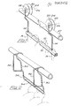
- Fig. 1 there is shown a conventional suspension unit for a suspension conveyor system.
- the unit which is sometimes referred to as a trolley, comprises a rod or bar 10, having a zig zag shaped wire 12 welded to the top surface thereof, in order to provide a plurality of recesses and grooves for receiving individual coat hangers as indicated in dotted lines.
- the rod At each end the rod is provided with a swivel bracket 14, and each bracket is pivotable about the vertical axis indicated in the drawing by reference 16.
- Each bracket 14 is somewhat in the shape of a question mark, and at its upper end carries a diablo roller bearing 20 of which the outer race 22 is provided with a v-shaped groove 24, and which outer race is freely rotatable about a horizontal axis 26.
- To position the trolley on a circular sectioned conveyor rail 27 of the suspension conveyor system it is simply hooked on so that the rail engages between the faces of the groove of each diablo roller as shown in Fig. 1.
- the pivoting of the bracket 16 enables the unit to "steer” as it travels round curves in the suspension system. These units have a tendency to derail, especially when unloaded, and it is believed that it is because of the manner by which the units are suspended from the rail using the individual diablo rollers.
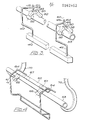
- the set which is illustrated in Fig. 2 is intended simply to be a hook on unit, and although these units are some times pushed along the guide rail, they are not specifically designed for this purpose.
- Each unit comprises a metal framework being in the form of a pair of hooks 30, handle portions 32, and the handle portions are connected by a suspension bar portion 34.
- the additional rod 36 serves the purpose of keeping hangers on the set during transit in transportation vehicles. These sets are usually man handled from place to place, although sometimes they are suspended from the bars 10 of the mobile suspension unit such as illustrated in Fig. 1.
- the present invention is concerned with the utilisation of individual roller bearings defining a V suspension arrangement, and Figs. 3 and 4 show how suspension units or trolleys and sets can be constructed in accordance with the present invention.
- the trolley illustrated again comprises a bar 40 similar to bar 10, but this time it is provided with brackets 42 which are fixed to bar 40. At their upper ends, the brackets 42 are provided with sleeves 44 swiveably to receive pins 46 of mounting brackets 48.
- the mounting brackets 48 carry stub axles 50 on which are mounted roller bearings 52. The outer races of these bearings 52 engage the opposite sides of the guide rail 53 of the conveyor suspension system when in use, and the said outer races 54 are slightly waisted for this purpose.
- the axis of swivelling of the mounting is indicated by reference 60, and it will therefore be seen quite clearly that this unit can steer and in addition has the advantage that the individual roller bearings associated with each mounting can rotate differentially in that each is independently rotatable, and this is of advantage when the unit is travelling around curved portions of the guide rail.
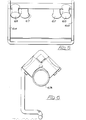
- the set 61 is essentially of the same overall dimensions as the set shown in Fig. 2, but in addition there is provided a mounting bar 62 extending between the end hooked portion 64, and the mounting bar carries two pairs of roller bearings 65,67.
- the pairs of roller bearings 65,67 are symmetrically arranged in relation to a central plane bisecting the set as shown in the side elevation of Fig. 5 and each roller bearing pair comprises an inner roller bearing 67 and an outer roller bearing 65, the expressions inner and outer being applied to the position in relation to the central plane of the set.
- the inner and outer roller bearings 67,65 of each pair are arranged on stub axles projecting from the mounting bar 60 so as to define a downwardly open v-shape, as shown clearly in Fig. 6, and the outer races of the roller bearings are waisted, also shown clearly in Fig. 6, so as to ensure a neater engagement on the circular sectioned guide bar, with which the sets will be used, all as shown in Fig. 6.
- Fig. 4 shows how the set is mounted on the guide rail 63, and also shows how the guide rail itself is suspended by means of hook shaped brackets (70).
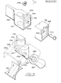
- each bracket 72 has a connector block 76 for connection to a top rail 78 which has V notches for engagement by overhead dogs when the carrier is power driven and carries the pairs of roller bearings 80 and 82 which function identically to the rollers 65 and 67 of the Figs. 4 to 6 embodiments.
- each bracket 72 has a second mounting block 84 for connection to the lower cross bar 86.
- the lower cross bar 86 has a curved upper edge 88 with grooves 90 therein for receiving coat hangers in much the same manner as illustrated in Fig. 1.
- connection blocks 92 and 94 The ends of the cross bars 78 and 86 have corresponding connection blocks 92 and 94 and the connections between the respective blocks 76 and 94 and 84 and 92 are made in the same fashion as illustrated clearly in Fig. 8 which shows a connecting block 94 of upper cross bar 78, and an upper connecting block 76 of a bracket 72. It will be seen that on the end face of connecting block 94 there is a square locating projection 96 of tapered configuration, and this projection locates in corresponding recess or socket on the opposing face of the block 76, such socket being in fact of the same configuration as the recess 98 illustrated in Fig. 8, so that the blocks accurately register and interfit.
- a screw or bolt 100 connects the blocks by passing through a bore 102 in block 76 and a bore 104 in block 96, and securement is achieved by placing a nut 106 in a reception slot 108 in block 94.
- the reception slot 108 is dimensioned so as to receive nut 106 slidably therein, but prevents the nut 106 from rotating when the screw or bolt 100 is screwed thereinto, and this feature can be achieved easily by moving the bar 78 from plastics material. All connections of the blocks 76, 94 and 84 and 92 are achieved in this fashion, the reception slots for the nuts being indicated in bar 86 by numeral 110.
- Fig. 8 also shows how the pairs of rollers 80 and 82 are mounted on the upper bar 78.
- each block 94 has a recess 112 therein, which opens to the underside of the block 94, and a corresponding peg 114 of a bearing support fixed neatly into such recess 112, the peg having a tapered end 116 to facilitate the insertion.
- the mounting 114 has a body 118 provided with a pair of mutually inclined faces 120 and 124 through which respectively are formed reception bores 126 and 128 for receiving the ends of spindles 130 and 132 which carry the inner races of the roller bearings or in fact form the said inner races.
- the said spindle ends 130 and 132 are push fitted into the bores 126 and 128, so as to lie at the appropriate angle as defined by the angle between the faces 120 and 124, as indicated more clearly in Fig. 6.
- a shroud or cover 134 which fits over the body 118 of the mounting, the peg in fact projecting through the shroud or cover, the said shroud or cover extending over the roller bearings 80 and 82 when in position, so as to protect same from damage in the event that the set falls to the ground.
- the shroud or cover may be in a plastics material which is more flexible than that of the other components
- the set constructed according to this embodiment can be fabricated quickly and easily making effective use of injection moulded components. All components of this set can be of plastics material, apart perhaps from the rolling elements of the roller bearings.
- the set With the arranyement described, the set becomes completely mobile on the guiderail and can be transported from for example a warehousing or storage department to a discharge point, and where approriate directly into the transportation vehicle.
- Such sets can therefore be used on an interchanged basis as the sets are used currently, so as the sets in fact circulate between different users.
- the time saved by using sets according to the invention, can be considerable.
- the invention can also be applied to replace the diablo in the single suspension units, being units in which a single diablo is used.
- roller bearings which are used in connection with the invention may be any suitable, in that the races may be constructed from metal and/or plastics, and the rolling elements may be balls and/or rollers, and whilst it is preferred that waisted or diablo type roller bearings be used, it is to be pointed out that this is not essential. Furthermore, it is possible to use rollers which are not roller bearings, rollers simply being rotatable on spindle means, but it is believed that the friction loading with such arrangements may make them commercially unattractive.
- the bottom rail (34 in Fig. 2 and equivalent in Figs. 4 to 8) may be in the form of a shallow V to ensure that the hangers gravitate to the centre of the rail, and/or the bottom rail may have individual hangers apertures to receive individual hangers.
Landscapes
- Engineering & Computer Science (AREA)
- Mechanical Engineering (AREA)
- Vehicle Body Suspensions (AREA)
- Chain Conveyers (AREA)
- Carriers, Traveling Bodies, And Overhead Traveling Cranes (AREA)
Priority Applications (1)
| Application Number | Priority Date | Filing Date | Title |
|---|---|---|---|
| AT82301546T ATE25648T1 (de) | 1981-04-02 | 1982-03-24 | Gehaengeeinheiten fuer haengebahnsysteme. |
Applications Claiming Priority (2)
| Application Number | Priority Date | Filing Date | Title |
|---|---|---|---|
| GB8110361 | 1981-04-02 | ||
| GB8110361 | 1981-04-02 |
Publications (3)
| Publication Number | Publication Date |
|---|---|
| EP0062452A2 true EP0062452A2 (de) | 1982-10-13 |
| EP0062452A3 EP0062452A3 (en) | 1983-01-19 |
| EP0062452B1 EP0062452B1 (de) | 1987-03-04 |
Family
ID=10520859
Family Applications (1)
| Application Number | Title | Priority Date | Filing Date |
|---|---|---|---|
| EP82301546A Expired EP0062452B1 (de) | 1981-04-02 | 1982-03-24 | Gehängeeinheiten für Hängebahnsysteme |
Country Status (3)
| Country | Link |
|---|---|
| EP (1) | EP0062452B1 (de) |
| AT (1) | ATE25648T1 (de) |
| DE (1) | DE3275533D1 (de) |
Cited By (6)
| Publication number | Priority date | Publication date | Assignee | Title |
|---|---|---|---|---|
| FR2720763A1 (fr) * | 1994-06-03 | 1995-12-08 | Sabim | Rail pour le transport de charges suspendues. |
| FR2782328A1 (fr) | 1998-08-12 | 2000-02-18 | Normandie Manutention | Systeme de rail destine au support, au roulement et/ou glissement d'un chariot, pour l'industrie agro-alimentaire |
| ES2168965A1 (es) * | 2000-06-09 | 2002-06-16 | Llados Albert Mimo | Instalacion de transporte por guias, en especial para el transporte aereo de prendas de vestir. |
| WO2008098596A1 (de) * | 2007-02-16 | 2008-08-21 | Rsl Logistik Gmbh & Co. Kg | Fördermittel für eine hängefördereinrichtung |
| NL1034835C2 (nl) * | 2007-12-18 | 2009-06-19 | Baggermans Holding B V | Inrichting voor het oogsten van langstelige gewassen in een warenhuis. |
| EP2036846A3 (de) * | 2007-09-14 | 2012-05-30 | Heidelberger Druckmaschinen Aktiengesellschaft | Transportsystem |
Family Cites Families (5)
| Publication number | Priority date | Publication date | Assignee | Title |
|---|---|---|---|---|
| CH394038A (de) * | 1962-04-25 | 1965-06-15 | Algemene Transport En Expediti | Verfahren zum Befördern von Kleidungsstücken, und Träger zur Durchführung dieses Verfahrens |
| DE1922473U (de) * | 1965-04-24 | 1965-08-26 | Egon Wette | Haengeschienen-transportwagen fuer kleidungsstuecke. |
| US3759190A (en) * | 1972-02-14 | 1973-09-18 | Fair Conn Inc | Trolley wheel |
| DE2550556A1 (de) * | 1975-11-11 | 1977-05-12 | Adolf Haubner | Schwebebahn fuer spielanlagen o.dgl. |
| DE3019644C2 (de) * | 1980-05-22 | 1986-10-02 | Franz 8741 Unterelsbach Gärtner | Fördereinrichtung |
-
1982
- 1982-03-24 EP EP82301546A patent/EP0062452B1/de not_active Expired
- 1982-03-24 AT AT82301546T patent/ATE25648T1/de not_active IP Right Cessation
- 1982-03-24 DE DE8282301546T patent/DE3275533D1/de not_active Expired
Cited By (7)
| Publication number | Priority date | Publication date | Assignee | Title |
|---|---|---|---|---|
| FR2720763A1 (fr) * | 1994-06-03 | 1995-12-08 | Sabim | Rail pour le transport de charges suspendues. |
| WO1995033888A1 (fr) * | 1994-06-03 | 1995-12-14 | Societe Anonyme Des Abattoirs Imperator Sabim | Rail pour le transport de charges suspendues |
| FR2782328A1 (fr) | 1998-08-12 | 2000-02-18 | Normandie Manutention | Systeme de rail destine au support, au roulement et/ou glissement d'un chariot, pour l'industrie agro-alimentaire |
| ES2168965A1 (es) * | 2000-06-09 | 2002-06-16 | Llados Albert Mimo | Instalacion de transporte por guias, en especial para el transporte aereo de prendas de vestir. |
| WO2008098596A1 (de) * | 2007-02-16 | 2008-08-21 | Rsl Logistik Gmbh & Co. Kg | Fördermittel für eine hängefördereinrichtung |
| EP2036846A3 (de) * | 2007-09-14 | 2012-05-30 | Heidelberger Druckmaschinen Aktiengesellschaft | Transportsystem |
| NL1034835C2 (nl) * | 2007-12-18 | 2009-06-19 | Baggermans Holding B V | Inrichting voor het oogsten van langstelige gewassen in een warenhuis. |
Also Published As
| Publication number | Publication date |
|---|---|
| ATE25648T1 (de) | 1987-03-15 |
| EP0062452B1 (de) | 1987-03-04 |
| DE3275533D1 (en) | 1987-04-09 |
| EP0062452A3 (en) | 1983-01-19 |
Similar Documents
| Publication | Publication Date | Title |
|---|---|---|
| US10829320B2 (en) | Conveyor system for the conveying of goods items | |
| US3854573A (en) | Load carrier with dual pin suspension | |
| US6324992B1 (en) | Hybrid carrying truck | |
| US3727745A (en) | Conveyor rail | |
| EP0062452B1 (de) | Gehängeeinheiten für Hängebahnsysteme | |
| DE69916028D1 (de) | Förderer für die Industrie zum Fördern von Bauteilen in grossen Mengen | |
| US2808146A (en) | Endless conveyors | |
| US3010584A (en) | Article storing and delivering apparatus with inclined article-supporting rack | |
| JPS6250362B2 (de) | ||
| US3426912A (en) | Rack conveying system | |
| US4474286A (en) | Close-pack conveyor system | |
| JPH10291627A (ja) | 吊り下げ搬送装置 | |
| US3659532A (en) | Pallet and rail material handling apparatus | |
| GB2152463A (en) | Powered overhead conveyor systems | |
| DE3660007D1 (en) | Conveyor with a suspension support | |
| US2981203A (en) | Conveyor power chain | |
| US3004498A (en) | Conveyor power chain load pick-up unit | |
| US3008430A (en) | Chain conveyors | |
| CN218663700U (zh) | 挂架运输用驱动轨道及轨道机构 | |
| CN213084538U (zh) | 一种多节式物流用输送装置 | |
| CN215088928U (zh) | 一种物流分拣用摆动轮 | |
| CN219728994U (zh) | 一种防货物倾倒的运输装置 | |
| JPS6033619B2 (ja) | 物品の搬送装置 | |
| GB2161442A (en) | Conveyor | |
| JPH088938Y2 (ja) | 吊下搬送装置のハンガー揺れ止め機構 |
Legal Events
| Date | Code | Title | Description |
|---|---|---|---|
| PUAI | Public reference made under article 153(3) epc to a published international application that has entered the european phase |
Free format text: ORIGINAL CODE: 0009012 |
|
| AK | Designated contracting states |
Designated state(s): AT BE CH DE FR GB IT LU NL SE |
|
| PUAL | Search report despatched |
Free format text: ORIGINAL CODE: 0009013 |
|
| AK | Designated contracting states |
Designated state(s): AT BE CH DE FR GB IT LI LU NL SE |
|
| 17P | Request for examination filed |
Effective date: 19830704 |
|
| ITF | It: translation for a ep patent filed | ||
| GRAA | (expected) grant |
Free format text: ORIGINAL CODE: 0009210 |
|
| AK | Designated contracting states |
Kind code of ref document: B1 Designated state(s): AT BE CH DE FR GB IT LI LU NL SE |
|
| REF | Corresponds to: |
Ref document number: 25648 Country of ref document: AT Date of ref document: 19870315 Kind code of ref document: T |
|
| PG25 | Lapsed in a contracting state [announced via postgrant information from national office to epo] |
Ref country code: LU Free format text: LAPSE BECAUSE OF NON-PAYMENT OF DUE FEES Effective date: 19870331 |
|
| PGFP | Annual fee paid to national office [announced via postgrant information from national office to epo] |
Ref country code: NL Payment date: 19870331 Year of fee payment: 6 |
|
| ET | Fr: translation filed | ||
| REF | Corresponds to: |
Ref document number: 3275533 Country of ref document: DE Date of ref document: 19870409 |
|
| PLBE | No opposition filed within time limit |
Free format text: ORIGINAL CODE: 0009261 |
|
| STAA | Information on the status of an ep patent application or granted ep patent |
Free format text: STATUS: NO OPPOSITION FILED WITHIN TIME LIMIT |
|
| 26N | No opposition filed | ||
| PG25 | Lapsed in a contracting state [announced via postgrant information from national office to epo] |
Ref country code: GB Effective date: 19890324 Ref country code: AT Effective date: 19890324 |
|
| PG25 | Lapsed in a contracting state [announced via postgrant information from national office to epo] |
Ref country code: SE Effective date: 19890325 |
|
| PG25 | Lapsed in a contracting state [announced via postgrant information from national office to epo] |
Ref country code: LI Effective date: 19890331 Ref country code: CH Effective date: 19890331 Ref country code: BE Effective date: 19890331 |
|
| BERE | Be: lapsed |
Owner name: GARNETT DAVID MORRIS Effective date: 19890331 |
|
| PG25 | Lapsed in a contracting state [announced via postgrant information from national office to epo] |
Ref country code: NL Effective date: 19891001 |
|
| NLV4 | Nl: lapsed or anulled due to non-payment of the annual fee | ||
| GBPC | Gb: european patent ceased through non-payment of renewal fee | ||
| PG25 | Lapsed in a contracting state [announced via postgrant information from national office to epo] |
Ref country code: FR Free format text: LAPSE BECAUSE OF NON-PAYMENT OF DUE FEES Effective date: 19891130 |
|
| REG | Reference to a national code |
Ref country code: CH Ref legal event code: PL |
|
| PG25 | Lapsed in a contracting state [announced via postgrant information from national office to epo] |
Ref country code: DE Effective date: 19891201 |
|
| REG | Reference to a national code |
Ref country code: FR Ref legal event code: ST |
|
| EUG | Se: european patent has lapsed |
Ref document number: 82301546.6 Effective date: 19900124 |