EP0062418A2 - Protection system for a propulsion unit attachable to a boat - Google Patents
Protection system for a propulsion unit attachable to a boat Download PDFInfo
- Publication number
- EP0062418A2 EP0062418A2 EP82301268A EP82301268A EP0062418A2 EP 0062418 A2 EP0062418 A2 EP 0062418A2 EP 82301268 A EP82301268 A EP 82301268A EP 82301268 A EP82301268 A EP 82301268A EP 0062418 A2 EP0062418 A2 EP 0062418A2
- Authority
- EP
- European Patent Office
- Prior art keywords
- propulsion unit
- release
- detent means
- cage
- detent
- Prior art date
- Legal status (The legal status is an assumption and is not a legal conclusion. Google has not performed a legal analysis and makes no representation as to the accuracy of the status listed.)
- Withdrawn
Links
Images

Classifications
-
- B—PERFORMING OPERATIONS; TRANSPORTING
- B63—SHIPS OR OTHER WATERBORNE VESSELS; RELATED EQUIPMENT
- B63H—MARINE PROPULSION OR STEERING
- B63H20/00—Outboard propulsion units, e.g. outboard motors or Z-drives; Arrangements thereof on vessels
- B63H20/08—Means enabling movement of the position of the propulsion element, e.g. for trim, tilt or steering; Control of trim or tilt
- B63H20/10—Means enabling trim or tilt, or lifting of the propulsion element when an obstruction is hit; Control of trim or tilt
- B63H20/106—Means enabling lifting of the propulsion element in a substantially vertical, linearly sliding movement
-
- B—PERFORMING OPERATIONS; TRANSPORTING
- B63—SHIPS OR OTHER WATERBORNE VESSELS; RELATED EQUIPMENT
- B63H—MARINE PROPULSION OR STEERING
- B63H20/00—Outboard propulsion units, e.g. outboard motors or Z-drives; Arrangements thereof on vessels
- B63H20/36—Transporting or testing stands ; Use of outboard propulsion units as pumps; Protection of power legs, e.g. when not in use
-
- B—PERFORMING OPERATIONS; TRANSPORTING
- B63—SHIPS OR OTHER WATERBORNE VESSELS; RELATED EQUIPMENT
- B63H—MARINE PROPULSION OR STEERING
- B63H5/00—Arrangements on vessels of propulsion elements directly acting on water
- B63H5/07—Arrangements on vessels of propulsion elements directly acting on water of propellers
- B63H5/125—Arrangements on vessels of propulsion elements directly acting on water of propellers movably mounted with respect to hull, e.g. adjustable in direction, e.g. podded azimuthing thrusters
-
- B—PERFORMING OPERATIONS; TRANSPORTING
- B63—SHIPS OR OTHER WATERBORNE VESSELS; RELATED EQUIPMENT
- B63H—MARINE PROPULSION OR STEERING
- B63H5/00—Arrangements on vessels of propulsion elements directly acting on water
- B63H5/07—Arrangements on vessels of propulsion elements directly acting on water of propellers
- B63H5/16—Arrangements on vessels of propulsion elements directly acting on water of propellers characterised by being mounted in recesses; with stationary water-guiding elements; Means to prevent fouling of the propeller, e.g. guards, cages or screens
- B63H5/165—Propeller guards, line cutters or other means for protecting propellers or rudders
Landscapes
- Engineering & Computer Science (AREA)
- Chemical & Material Sciences (AREA)
- Combustion & Propulsion (AREA)
- Mechanical Engineering (AREA)
- Ocean & Marine Engineering (AREA)
- Transportation (AREA)
- Earth Drilling (AREA)
- Investigating Or Analyzing Materials By The Use Of Magnetic Means (AREA)
- Current-Collector Devices For Electrically Propelled Vehicles (AREA)
Abstract
Description
- This invention relates to a protection system for a propulsion unit which is pendently attachable to a boat or a pontoon, an outboard motor for example.
- Protection systems are known which rely upon mounting the propulsion unit on a horizontal pivot and providing a shear pin to hold the unit in a vertical position. If the unit is struck from the front by an underwater obstruction the pin shears and the unit pivots upwards to clear the obstruction. This system suffers from the disadvantage that the shear pin has to be replaced before the unit can be deployed. Furthermore the system only protects against blows from the front, no protection being provided against blows in an upwards or sideways direction, such as may occur when a pontoon, for example, is swept sideways by a current or is loaded rapidly in shallow water and its draught changes in a few seconds crushing the propulsion unit against the bottom.
- Other protection systems are known in which the propulsion unit is raised and lowered by means of a pantographic framework but the protection afforded is again limited to blows received from a substantially forward direction.
- The present invention seeks to provide a readily re-deployable system which will protect against blows received in forward, reverse, sideways and upwards directions.
- In accordance with the present invention, a propulsion unit protection system includes: a support frame from which a propulsion unit is slideably protrusible by an externally applied force; retraction means energisable by protrusion of the propulsion unit; detent means for maintaining the propulsion unit in a protruded state against the pressure exerted by the energised retraction means; a sensing cage disposed about the propulsion unit and resiliently attached thereto; and a release means coupled between the sensing cage and the detent means so as to release the detent means when the disposition of the sensing cage relative to the propulsion unit is disturbed.
- The release means may be mechanical, hydraulic or pneumatic. One convenient mechanical arrangement comprises a contractible release arm which may consist of two articulated rigid members or alternatively a single flexible member,coupled at one end to the sensing cage via a ball joint and at the other to the detent means via a deflection amplifying lever. An impact against the cage in any direction other than outwardly from the support frame will cause increased cranking or bending of the release arm and hence contraction of the overall length of the arm so as to deflect the amplifying lever thereby to release the detent means.
- An alternative pneumatic arrangement may comprise one or more pneumatic chambers compressible between the sensing cage and the propulsion unit, which chambers are pneumatically coupled with a cylinder and piston arrangement operative upon the detent means so as to release the detent means when any one of the chambers is compressed. Alternatively, the pneumatic chambers may be replaced by piston and cylinder assemblies hydraulically coupled with the release means.
- The retraction means may conveniently comprise one or more helical compression springs axially disposed in the direction of sliding and compressible between the propulsion unit and the support frame when the propulsion unit is protruded. Alternatively pneumatic or hydraulic compression springs may be similarly employed or tension springs may be attached between the unit and the frame so as to be extended When the unit is protruded.
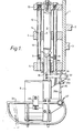
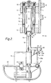
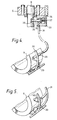
- An embodiment of the invention will now be described by way of example only with reference to the attached drawings of which Figures 1 and 2 are part-sectioned side elevations of a propulsion unit protection system having a mechanical detent release means, and drawn respectively with the propulsion unit retracted and protruded, Figure 3 is an end elevation of the same system viewed in the direction A of Figure 2, and Figures 4. and 5 are part views of alternative pneumatic and hydraulic detent release means respectively.
- The system illustrated in Figs. 1 and 2 comprises a
support frame 1 which is attachable to a vessel to be propelled viamembers upper platform 4 and alower platform 5 respectively havingcoaxial bores cylindrical post 8 is slideable. Thepost 8 supports at its lower end apropulsion unit 9 and is suspended from abearer plate 10, within which bearer plate it is captively rotatable about its own axis. - Two
helical compression springs 11 disposed so as to be compressible between thebearer plate 10 and thelower platform 5, are each housed within outer and innertelescopic sleeves outer sleeve 12 being attached to thebearer plate 10 and slideable within abore 14 in theupper platform 4 and theinner sleeve 13 being attached to thelower platform 5. - The
propulsion unit 9 can be manually protruded in a downwards direction from theframe 1 by pressing thebearer plate 10 towards theupper platform 4. A detent means is provided for holding the propulsion unit in the protruded position which comprises a spring biassedcatch post 8, within a bifurcatedportion 8a thereof, at atransverse pivot 16. The catch deflects upwardly to pass through thebore 7 when thepost 8 is depressed, thereafter to snap into engagement with alock ring 17 mounted at the lower end of thebore 7. Apull rod 18 rotatably attached to thecatch 15 is articulated to adeflection amplifying lever 19 which is rotatable about apivot 20 laterally disposed between a pair ofcheek plates 21 attached to thepost 8. - A
sensing cage 22 shaped to protect thepropulsion unit 9 against upward, sideways, forward and rearward blows, is attached to the unit atclamps 23 via resilient bondings 24 (Figure 3) which bondings ensure relative re-centralisation of the cage and the unit after receipt of a blow. - The
sensing cage 22 and thelever 19 are coupled together by a jointeddetent release arm 25 consisting of two pivotally interconnectedmembers member 25 a being attached to thelever 19 at apivot 26 andmember 25 b being connected to thecage 22 via a ball joint 27 (Figure 3). Any upwardly or laterally acting blow upon the cage will cause thejointed arm 25 to momentarily flex thus shortening its overall length and so rotating thelever 19 anti-clockwise (as drawn). This in turn pulls thepull rod 18 downwards to release thecatch 15 from thelock ring 17 thereby releasing the energy stored in thesprings 11 to rapidly raise the propulsion unit. - The length and weight of the springs are selected to raise the propulsion unit in approximately 0.1 seconds, the estimated time for preventing damage to the unit when travelling at speeds of up to 7 knots.
- An alternative pneumatic detent release means is illustrated in Figure 4 which comprises a plurality of
compressible chambers 29 evenly disposed interjacent thepropulsion unit 9 and asensing oage 30 so as to be compressed between them when the cage is struck, at least one being compressed whatever the direction of the blow. The chambers are pneumatically coupled in series connection via atube 31 to aninlet port 32 of acylinder block 33 attached to thelower platform 5. - The
cylinder block 33 contains a piston 34 bearing adetent stub 35 which engages with arecess 36 in thepost 8, the stub being biassed into engagement with the recess by aspring 37. - In operation, any impact to the
cage 30 causes at least one of thechambers 29 to be compressed, thus transmitting a pressure pulse via thetube 31 which overrides the pressure of thespring 37 to disengage thedetent stub 35 from therecess 36. - An alternative, hydraulically operated detent release means is illustrated in Figure 5 in which the
compressible chambers 29 of Figure 4 are replaced by piston andcylinder assemblies 40 hydraulically coupled via thetube 31 to the detent release means. - A particular advantage of the invention is that the propulsion unit can be speedily reset to the protruded position once an obstruction has been cleared, by simple manual pressure upon the bearer plate, no replacement of components being necessary.
- The specific propulsion unit illustrated has a hydraulic drive (not shown) but the invention is of course equally applicable to conventional propulsion units having mechanical drive.
Claims (9)
Applications Claiming Priority (2)
| Application Number | Priority Date | Filing Date | Title |
|---|---|---|---|
| GB8110674 | 1981-04-06 | ||
| GB8110674 | 1981-04-06 |
Publications (2)
| Publication Number | Publication Date |
|---|---|
| EP0062418A2 true EP0062418A2 (en) | 1982-10-13 |
| EP0062418A3 EP0062418A3 (en) | 1983-04-06 |
Family
ID=10520952
Family Applications (1)
| Application Number | Title | Priority Date | Filing Date |
|---|---|---|---|
| EP82301268A Withdrawn EP0062418A3 (en) | 1981-04-06 | 1982-03-12 | Protection system for a propulsion unit attachable to a boat |
Country Status (2)
| Country | Link |
|---|---|
| EP (1) | EP0062418A3 (en) |
| GB (1) | GB2096082B (en) |
Citations (5)
| Publication number | Priority date | Publication date | Assignee | Title |
|---|---|---|---|---|
| FR16519E (en) * | 1911-12-12 | 1913-02-21 | Jean De Bosredon | Motor boat with very shallow draft and its equipment for hunting |
| US2479119A (en) * | 1943-07-30 | 1949-08-16 | Harold I Johnson | Propeller drive unit with automatic depth regulation |
| US2706959A (en) * | 1953-10-20 | 1955-04-26 | Alva D Downs | Safety mount for an outboard motor |
| GB934877A (en) * | 1960-09-20 | 1963-08-21 | Instr Res Lab Ltd | Marine propulsion unit attachable to boats |
| GB1040621A (en) * | 1962-03-23 | 1966-09-01 | Reiners Walter | A marine outboard drive |
-
1982
- 1982-03-12 EP EP82301268A patent/EP0062418A3/en not_active Withdrawn
- 1982-04-02 GB GB8209868A patent/GB2096082B/en not_active Expired
Patent Citations (5)
| Publication number | Priority date | Publication date | Assignee | Title |
|---|---|---|---|---|
| FR16519E (en) * | 1911-12-12 | 1913-02-21 | Jean De Bosredon | Motor boat with very shallow draft and its equipment for hunting |
| US2479119A (en) * | 1943-07-30 | 1949-08-16 | Harold I Johnson | Propeller drive unit with automatic depth regulation |
| US2706959A (en) * | 1953-10-20 | 1955-04-26 | Alva D Downs | Safety mount for an outboard motor |
| GB934877A (en) * | 1960-09-20 | 1963-08-21 | Instr Res Lab Ltd | Marine propulsion unit attachable to boats |
| GB1040621A (en) * | 1962-03-23 | 1966-09-01 | Reiners Walter | A marine outboard drive |
Also Published As
| Publication number | Publication date |
|---|---|
| GB2096082B (en) | 1984-06-27 |
| GB2096082A (en) | 1982-10-13 |
| EP0062418A3 (en) | 1983-04-06 |
Similar Documents
| Publication | Publication Date | Title |
|---|---|---|
| US4119225A (en) | Mounting means for attaching an implement to a vehicle | |
| EP0149528A1 (en) | Device for replacing mains | |
| US4759437A (en) | Handrail for aircraft belt loader | |
| SE458534B (en) | DEVICE FOR A QUICK CONNECTION FOR UNLOCKABLE COUPLING OF A WORKING TOOL AND AN EXCAVATOR MANUAL ARM | |
| US4561505A (en) | Hinge mechanism for folding tool bar assembly including hook engageable over pivotal connection | |
| US4331431A (en) | Transom saver | |
| US5720122A (en) | Plow blade with adjustable scraping bar | |
| US4053174A (en) | Load transferring trailer hitch device | |
| EP0540805B1 (en) | Boom extension alignment device | |
| EP0062418A2 (en) | Protection system for a propulsion unit attachable to a boat | |
| US5855245A (en) | Disk opener carrier hitch | |
| US5927226A (en) | Combined towing and docking hitch for watercraft | |
| JP2923174B2 (en) | Ship mooring and berthing support equipment. | |
| GB2040260A (en) | Boom apparatus | |
| US4335670A (en) | Flexible side connector for floating and elevated platforms | |
| GB1587979A (en) | Device for keeping constant the tensile stress in a cable | |
| US4520878A (en) | Spring cushion chisel plow shank assembly | |
| US3145003A (en) | Outboard motor mounting | |
| GB1600520A (en) | Hydraulic self-advancing roofsupport frame | |
| GB1600846A (en) | Coupling member | |
| US4792006A (en) | Drive shaft coupling | |
| US3520117A (en) | Underwater weed cutter mechanisms | |
| GB2267756A (en) | Obstacle sensor for an underwater transducer assembly | |
| CN207762051U (en) | Cylinder rod protective case | |
| US4432402A (en) | Self-elevating wood splitter |
Legal Events
| Date | Code | Title | Description |
|---|---|---|---|
| PUAI | Public reference made under article 153(3) epc to a published international application that has entered the european phase |
Free format text: ORIGINAL CODE: 0009012 |
|
| AK | Designated contracting states |
Designated state(s): BE CH DE FR IT NL SE |
|
| PUAL | Search report despatched |
Free format text: ORIGINAL CODE: 0009013 |
|
| AK | Designated contracting states |
Designated state(s): BE CH DE FR IT LI NL SE |
|
| 17P | Request for examination filed |
Effective date: 19830329 |
|
| STAA | Information on the status of an ep patent application or granted ep patent |
Free format text: STATUS: THE APPLICATION HAS BEEN WITHDRAWN |
|
| 18W | Application withdrawn |
Withdrawal date: 19850208 |
|
| PGFP | Annual fee paid to national office [announced via postgrant information from national office to epo] |
Ref country code: LU Payment date: 19890405 Year of fee payment: 8 |
|
| RIN1 | Information on inventor provided before grant (corrected) |
Inventor name: HANCE, JOHN EDWARD Inventor name: FITZGERALD-SMITH, JAMES PATRICK |