EP0062402A2 - Burner - Google Patents
Burner Download PDFInfo
- Publication number
- EP0062402A2 EP0062402A2 EP82300795A EP82300795A EP0062402A2 EP 0062402 A2 EP0062402 A2 EP 0062402A2 EP 82300795 A EP82300795 A EP 82300795A EP 82300795 A EP82300795 A EP 82300795A EP 0062402 A2 EP0062402 A2 EP 0062402A2
- Authority
- EP
- European Patent Office
- Prior art keywords
- fuel gas
- plate
- burner according
- angle
- burner
- Prior art date
- Legal status (The legal status is an assumption and is not a legal conclusion. Google has not performed a legal analysis and makes no representation as to the accuracy of the status listed.)
- Granted
Links
Images

Classifications
-
- F—MECHANICAL ENGINEERING; LIGHTING; HEATING; WEAPONS; BLASTING
- F23—COMBUSTION APPARATUS; COMBUSTION PROCESSES
- F23G—CREMATION FURNACES; CONSUMING WASTE PRODUCTS BY COMBUSTION
- F23G7/00—Incinerators or other apparatus for consuming industrial waste, e.g. chemicals
- F23G7/06—Incinerators or other apparatus for consuming industrial waste, e.g. chemicals of waste gases or noxious gases, e.g. exhaust gases
- F23G7/08—Incinerators or other apparatus for consuming industrial waste, e.g. chemicals of waste gases or noxious gases, e.g. exhaust gases using flares, e.g. in stacks
-
- F—MECHANICAL ENGINEERING; LIGHTING; HEATING; WEAPONS; BLASTING
- F23—COMBUSTION APPARATUS; COMBUSTION PROCESSES
- F23D—BURNERS
- F23D14/00—Burners for combustion of a gas, e.g. of a gas stored under pressure as a liquid
- F23D14/46—Details
- F23D14/70—Baffles or like flow-disturbing devices
Definitions
- the present invention relates to burners and more particularly to burners used for the disposal of refinery gases or gases from other oil or chemical plant.
- the burners are often used as part of a ground flare.
- a problem with ground flares is that the chimney requires a refractory or insulating lining to prevent the outer metal wall from becoming too hot. Highly radiative flames give rise to high temperatures and high thermal stresses in the refractory materials which can cause cracking and even eventual failure of the refractory.
- the present invention relates to an improved burner suitable for burning refinery or other gas with a relatively shorter and less radiative flame and which has relatively fewer maintenance problems and which is suitable for use in a ground fired flarestack.
- a burner suitable for use in a concealed flare comprising a fuel gas supply pipe having a low resistance to upward air flow, the pipe having one or more outlets, a plate adjacent and at an angle to each outlet whereby the angle of fuel gas impingement on the plate is at an angle of 1° to 55°, means for passing air upwardly past the outlets and plates, and means for retaining the flame resulting from combustion of the fuel gas and air.
- the burner of the present invention has certain features differing from the prior art.
- the gas supply pipes have low resistance to upward aspirated air flow
- the angle of the plate and outlet gas flow gives good spreading and hence mixing of the fuel gas and air giving a less radiative and shorter flame
- the presence of means for flame retention is not limited to the prior art.
- the burner preferably has a chimney or the like above it so as to produce a flow of aspirated air from below the burner to mix with the fuel gas.
- air may be blown through the burner, e.g. using a fan.
- the burner may comprise a single fuel gas pipe, but preferably the burner comprises an array of fuel gas pipes, most preferably arranged in parallel rows.
- the fuel gas pipes have a cross-section giving low aerodynamic resistance in the direction of air flow which reduces local turbulence at the burners and gives rise to better mixing of fuel and air. Preferably this is achieved by use of smooth pipes of greater dimension in the direct of the air flow, e.g. of elliptical section. This is in contrast to typical refinery burners comprising a circular cross-section pipe with fuel gas outlet holes in its upper surface which provides a bluff shape with high resistance to air flow leading to local turbulence and relatively poor mixing.
- the plate has associated flame retention means which preferably comprise the upper edge of the plate being turned over in the direction of the fuel gas outlet, most preferably to a horizontal position.
- the flame retention means reduces the tendency of the flame to lift off by providing a turbulent "anchor" zone of fuel gas and air.
- the plate itself is preferably flat and is of a size to cause spreading and mixing of the fuel gas with air.
- the plates are preferably fabricated from stainless steel.
- the fin plate allows the fuel gas to spread out as a laminar layer across the plate and in combination with the flame retention means gives a stable flame remote from the fuel gas outlets thereby reducing heating of and carbon build-up in the fuel gas supply pipes.
- the carbon build-up is believed to be caused not by deposition from the flame but by excessively high temperatures of the fuel gas supply tubes giving rise to pyrolysis of the fuel gas.
- the fuel gas outlet holes are preferably positioned in the upper surface of the fuel gas supply pipe.
- the fuel gas outlets may be fabricated to angle the fuel gas onto the plate, (b) the fuel gas may emerge vertically from the hole, the plate being angled and close enough to the outlet to give impingement,or a combination of (a) and (b) may be used.
- the preferred feature is arrangement (b).
- Another embodiment of the invention has fuel gas outlet holes comprising further pipes projecting from the upper surface of the fuel gas supply pipe, the further pipes having outlet holes directing fuel gas onto the adjacent plate.
- the fuel outlet may be circular in shape, but preferably it is shaped so as to assist spreading the fuel gas over the plate and an elliptical outlet is a preferred configuration.
- the plate is preferably fixed to the upper surface of the gas supply pipe, most preferably by welding.
- the angle of fuel gas impingement on the plate is at an angle of 1° to 55° and in one embodiment the fuel gas flow emerges vertically from the outlet and most preferably the plate is inclined towards the outlet so as to make an angle of up to 10° from the vertical, the preferred range being from 4° to 7°.
- the fuel gas outlet comprises a pipe projecting from the fuel supply pipe towards a preferably vertical plate, the angle between the emergent fuel gas flow and the plate being preferably 40° to 55°, the most preferred range being 47° to 51°.
- the preferred dimensions are chosen to give the optimum flame conditions without the angle of fuel gas flow either causing the flame to lift off or to cause unacceptable carbon build-up in the fuel supply pipes.
- the plates are preferably discrete entities but may be a single long plate across the burner or a linked series of single plates.
- ignition of the burner may be facilitated as turbulence at the upper ends of the edges of the plates tends to promote cross lighting across the burner.
- a radiant heat screen preferably in the form of a triangular cross-section strip of metal, may be positioned above the common fuel supply pipe so as to prevent overheating due to gas recirculation and direct flame impingement.
- a ground flare comprising a supply pipe for fuel gas, the supply pipe being connected to a burner as hereinbefore described, and an enclosure having vertical walls, the lower ends of which are above ground level thereby allowing access of air to the burner element within the enclosure.
- the internal walls of the flare are preferably metallic and lined with a refractory material, e.g. firebricks, castable or plastic refractory material, ceramic fibre.
- a draught or wind fence encloses the base of the flare. The draught fence may be slatted so that air can flow through the fence and then into the flare.
- the flare may be lit using conventional ignition procedures.
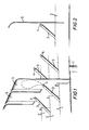
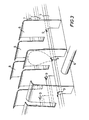
- Figures 1 and 3 are perspective views of two embodiments of the burner element.
- Figures 2 is a side view of a single unit of the first embodiment of the burner element.
- Figures 4(a), 4(b) and 4(c) show a side view of a second embodiment of the burner element, a vertical section through the main fuel gas supply line looking towards the secondary fuel gas line and a vertical cross-section of the secondary fuel gas line respectively.
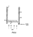
- Figure 5 is a schematic view of a ground flare incorporating the burner element.
- the burner element comprises a main fuel gas supply line 1 which feeds a plurality of parallel secondary fuel gas lines 2.
- the secondary lines 2 are fabricated from steel and take the form of narrow vertical flattened tubes having a height of 4.0 cms, maximum width of 1.0 cms and length 50 cms.
- the tubes present a narrow cross-section and give a low aerodynamic resistance to air flowing upwards between the tubes.
- At regular distances along the secondary lines 2 are positioned a number of outlet nozzles 3.
- These outlet nozzles 3 take the form of narrow tubes of hole exit area 12 mm 2 in the plane of associated secondary line 2 and angled upwards at about 45°.
- Each nozzle 3 has a tapered outlet 4.
- the nozzles 3 may be arranged in pairs pointing towards each other, all pointing in the same direction or any other convenient arrangement. Adjacent to the exit of each outlet nozzle 3 is positioned a flat plate or fin 5.
- the plate 5 is fixed to the associated secondary line 2 by welding or other suitable means, the plate 5 being set at right angles to the line 2 in the direction towards the outlet nozzle 3.
- the optimum acute angle between the plate and the jet of fuel gas emerging from the outlet nozzle was from 45° to 50°. Although angles greater or less than these values are suitable under certain conditions, the flame becomes more unstable and has a tendency to lift off or, alternatively, some of the fuel gas tends to pass back towards the secondary gas lines causing carbon build-up to occur.
- the burner element comprises a main fuel gas line 6 which feeds a plurality of parallel secondary fuel gas lines 7.
- the gas line 6 is linked to the secondary line 7 by means of a sleeve which connects the interior of the line 6 to that of line 7 by means of holes 16.
- plates 8 are fixed by welding or other suitable means.
- the plates 8 are at an angle of 85° to the axis of the line 7.
- Fuel outlet holes 9 in the lines 7 lie adjacent to the base of the plates 8.
- the outlet holes 9 are cut so as to direct at least a part of the fuel gas onto the surface of the plate 8.
- the cross-section of the outlet holes was circular or elliptical.
- Figure 4(b) shows a radiant heat screen 15 of triangular cross-section which serves to protect the gas line 6 from direct flame impingement and recirculation of hot gases.
- the plate has its upper edge bent over to create a lip to prevent lift off of the flame and acts as a flame retainer.
- the to edge of the plate used in the experiments was bent over to an angle of up to 90°.
- Figure 5 shows a vertical cross-section of a ground fired flare having a burner element according to the invention.
- the burner element 10 is positioned at the base of the flare chimney.
- the chimney comprises an inner refractory material 11, an insulating centre portion 12 and an outer metal skin 13.
- fuel gas is mixed with aspirated air from the chimney draught to produce, after ignition of the combustible mixture, flames stabilising above the plates 14 of the burner element 10.
Landscapes
- Engineering & Computer Science (AREA)
- Environmental & Geological Engineering (AREA)
- Mechanical Engineering (AREA)
- General Engineering & Computer Science (AREA)
- Chemical & Material Sciences (AREA)
- Combustion & Propulsion (AREA)
- Pre-Mixing And Non-Premixing Gas Burner (AREA)
- Incineration Of Waste (AREA)
- Gas Burners (AREA)
Abstract
Description
- The present invention relates to burners and more particularly to burners used for the disposal of refinery gases or gases from other oil or chemical plant.
- Conventional refinery burners comprising a fuel gas feed tube having a number of outlet holes are well known. These burners are of simple construction and relatively straightforward to fabricate. However, they produce relatively long radiative flames with a relatively high smoking tendency caused by relatively poor aerodynamics. Also carbon build up in the feeder tube caused by back radiation and flame lick can cause the feeder tube to split, thereby reducing the burner efficiency or even disabling it until repairs can be effected.
- The burners are often used as part of a ground flare. A problem with ground flares is that the chimney requires a refractory or insulating lining to prevent the outer metal wall from becoming too hot. Highly radiative flames give rise to high temperatures and high thermal stresses in the refractory materials which can cause cracking and even eventual failure of the refractory.
- The present invention relates to an improved burner suitable for burning refinery or other gas with a relatively shorter and less radiative flame and which has relatively fewer maintenance problems and which is suitable for use in a ground fired flarestack.
- Thus according to the present invention there is provided a burner suitable for use in a concealed flare comprising a fuel gas supply pipe having a low resistance to upward air flow, the pipe having one or more outlets, a plate adjacent and at an angle to each outlet whereby the angle of fuel gas impingement on the plate is at an angle of 1° to 55°, means for passing air upwardly past the outlets and plates, and means for retaining the flame resulting from combustion of the fuel gas and air.
- The burner of the present invention has certain features differing from the prior art. Thus, (a) the gas supply pipes have low resistance to upward aspirated air flow, (b) the angle of the plate and outlet gas flow gives good spreading and hence mixing of the fuel gas and air giving a less radiative and shorter flame, and (c) the presence of means for flame retention.
- The burner preferably has a chimney or the like above it so as to produce a flow of aspirated air from below the burner to mix with the fuel gas. Alternatively, air may be blown through the burner, e.g. using a fan.
- The burner may comprise a single fuel gas pipe, but preferably the burner comprises an array of fuel gas pipes, most preferably arranged in parallel rows. The fuel gas pipes have a cross-section giving low aerodynamic resistance in the direction of air flow which reduces local turbulence at the burners and gives rise to better mixing of fuel and air. Preferably this is achieved by use of smooth pipes of greater dimension in the direct of the air flow, e.g. of elliptical section. This is in contrast to typical refinery burners comprising a circular cross-section pipe with fuel gas outlet holes in its upper surface which provides a bluff shape with high resistance to air flow leading to local turbulence and relatively poor mixing.
- The plate has associated flame retention means which preferably comprise the upper edge of the plate being turned over in the direction of the fuel gas outlet, most preferably to a horizontal position. The flame retention means reduces the tendency of the flame to lift off by providing a turbulent "anchor" zone of fuel gas and air. The plate itself is preferably flat and is of a size to cause spreading and mixing of the fuel gas with air. The plates are preferably fabricated from stainless steel. The fin plate allows the fuel gas to spread out as a laminar layer across the plate and in combination with the flame retention means gives a stable flame remote from the fuel gas outlets thereby reducing heating of and carbon build-up in the fuel gas supply pipes. The carbon build-up is believed to be caused not by deposition from the flame but by excessively high temperatures of the fuel gas supply tubes giving rise to pyrolysis of the fuel gas.
- The fuel gas outlet holes are preferably positioned in the upper surface of the fuel gas supply pipe. In order to obtain the required angle of impingement of the fuel gas on the plate (a) the fuel gas outlets may be fabricated to angle the fuel gas onto the plate, (b) the fuel gas may emerge vertically from the hole, the plate being angled and close enough to the outlet to give impingement,or a combination of (a) and (b) may be used. The preferred feature is arrangement (b). Another embodiment of the invention has fuel gas outlet holes comprising further pipes projecting from the upper surface of the fuel gas supply pipe, the further pipes having outlet holes directing fuel gas onto the adjacent plate.
- The fuel outlet may be circular in shape, but preferably it is shaped so as to assist spreading the fuel gas over the plate and an elliptical outlet is a preferred configuration.
- The plate is preferably fixed to the upper surface of the gas supply pipe, most preferably by welding.
- The angle of fuel gas impingement on the plate is at an angle of 1° to 55° and in one embodiment the fuel gas flow emerges vertically from the outlet and most preferably the plate is inclined towards the outlet so as to make an angle of up to 10° from the vertical, the preferred range being from 4° to 7°.
- In a second embodiment, the fuel gas outlet comprises a pipe projecting from the fuel supply pipe towards a preferably vertical plate, the angle between the emergent fuel gas flow and the plate being preferably 40° to 55°, the most preferred range being 47° to 51°. The preferred dimensions are chosen to give the optimum flame conditions without the angle of fuel gas flow either causing the flame to lift off or to cause unacceptable carbon build-up in the fuel supply pipes.
- In a burner comprising a plurality of fuel gas outlet holes and plates, the plates are preferably discrete entities but may be a single long plate across the burner or a linked series of single plates. By use of discrete or single plates, ignition of the burner may be facilitated as turbulence at the upper ends of the edges of the plates tends to promote cross lighting across the burner.
- A radiant heat screen, preferably in the form of a triangular cross-section strip of metal, may be positioned above the common fuel supply pipe so as to prevent overheating due to gas recirculation and direct flame impingement.
- The burner element as hereinbefore described may be used as part of a ground flare system. Thus, according to a further aspect of the invention, there is provided a ground flare comprising a supply pipe for fuel gas, the supply pipe being connected to a burner as hereinbefore described, and an enclosure having vertical walls, the lower ends of which are above ground level thereby allowing access of air to the burner element within the enclosure.
- The internal walls of the flare are preferably metallic and lined with a refractory material, e.g. firebricks, castable or plastic refractory material, ceramic fibre. Preferably a draught or wind fence encloses the base of the flare. The draught fence may be slatted so that air can flow through the fence and then into the flare.
- The flare may be lit using conventional ignition procedures.
- The invention will now be described by way of example only with reference to Figures 1 to 5 of the accompanying drawings.
- Figures 1 and 3 are perspective views of two embodiments of the burner element.
- Figures 2 is a side view of a single unit of the first embodiment of the burner element. Figures 4(a), 4(b) and 4(c) show a side view of a second embodiment of the burner element, a vertical section through the main fuel gas supply line looking towards the secondary fuel gas line and a vertical cross-section of the secondary fuel gas line respectively. Figure 5 is a schematic view of a ground flare incorporating the burner element.
- With reference to Figures 1 and 2, the burner element comprises a main fuel gas supply line 1 which feeds a plurality of parallel secondary
fuel gas lines 2. Thesecondary lines 2 are fabricated from steel and take the form of narrow vertical flattened tubes having a height of 4.0 cms, maximum width of 1.0 cms and length 50 cms. The tubes present a narrow cross-section and give a low aerodynamic resistance to air flowing upwards between the tubes. At regular distances along thesecondary lines 2 are positioned a number of outlet nozzles 3. These outlet nozzles 3 take the form of narrow tubes ofhole exit area 12 mm2 in the plane of associatedsecondary line 2 and angled upwards at about 45°. Each nozzle 3 has a tapered outlet 4. The nozzles 3 may be arranged in pairs pointing towards each other, all pointing in the same direction or any other convenient arrangement. Adjacent to the exit of each outlet nozzle 3 is positioned a flat plate orfin 5. Theplate 5 is fixed to the associatedsecondary line 2 by welding or other suitable means, theplate 5 being set at right angles to theline 2 in the direction towards the outlet nozzle 3. - During use of the burner, fuel gas emerging from the tapered end 4 of the nozzle 3 impinges on
plate 5 and spreads over the surface of theplate 5. This allows mixing of atmospheric air (or aspirated air) flowing upwardly between thesecondary fuel lines 2 and the fuel gas to provide a combustible mixture which burns at the upper end of theplate 5. This upper end is bent over to assist flame retention of the flame above the plates. - It was found experimentally that the optimum acute angle between the plate and the jet of fuel gas emerging from the outlet nozzle was from 45° to 50°. Although angles greater or less than these values are suitable under certain conditions, the flame becomes more unstable and has a tendency to lift off or, alternatively, some of the fuel gas tends to pass back towards the secondary gas lines causing carbon build-up to occur.
- With reference to Figures 3 and 4, the burner element comprises a main
fuel gas line 6 which feeds a plurality of parallel secondary fuel gas lines 7. Thegas line 6 is linked to the secondary line 7 by means of a sleeve which connects the interior of theline 6 to that of line 7 by means ofholes 16. At regular intervals along line 7,plates 8 are fixed by welding or other suitable means. Theplates 8 are at an angle of 85° to the axis of the line 7. Fuel outlet holes 9 in the lines 7 lie adjacent to the base of theplates 8. The outlet holes 9 are cut so as to direct at least a part of the fuel gas onto the surface of theplate 8. The cross-section of the outlet holes was circular or elliptical. Figure 4(b) shows aradiant heat screen 15 of triangular cross-section which serves to protect thegas line 6 from direct flame impingement and recirculation of hot gases. - During use of the burner, at least part of the fuel gas emerging from
outlet holes 9 impinges onplates 8 and spreads over the surface of theplates 8. This allows mixing of air and the fuel gas to provide a combustible mixture. - Experimental results for vertical fuel gas flow from the outlet holes showed that the optimum flame conditions were obtained for the plate angled towards the outlet holes by an angle of 4° to 7° from the vertical. At angles of greater than 7° from the vertical there was a tendency for turbulent air flow conditions to occur on the back of the plate which in certain cases could lead to the flame burning back down the plate which causes damage or disintegration of the plate.
- The plate has its upper edge bent over to create a lip to prevent lift off of the flame and acts as a flame retainer. The to edge of the plate used in the experiments was bent over to an angle of up to 90°.
- The upward flow of air past the outlet holes and plates was achieved by placing an enclosure or chimney around the burner so as to aspirate air upwardly through the burner. An alternative method of achieving this effect would be to use a fan or blower to force air upwardly through the burner.
- Figure 5 shows a vertical cross-section of a ground fired flare having a burner element according to the invention. The
burner element 10 is positioned at the base of the flare chimney. The chimney comprises an inner refractory material 11, an insulatingcentre portion 12 and anouter metal skin 13. During operation of the flare, fuel gas is mixed with aspirated air from the chimney draught to produce, after ignition of the combustible mixture, flames stabilising above theplates 14 of theburner element 10.
Claims (17)
Applications Claiming Priority (2)
| Application Number | Priority Date | Filing Date | Title |
|---|---|---|---|
| GB8105121 | 1981-02-18 | ||
| GB8105121 | 1981-02-18 |
Publications (3)
| Publication Number | Publication Date |
|---|---|
| EP0062402A2 true EP0062402A2 (en) | 1982-10-13 |
| EP0062402A3 EP0062402A3 (en) | 1983-01-26 |
| EP0062402B1 EP0062402B1 (en) | 1986-07-16 |
Family
ID=10519793
Family Applications (1)
| Application Number | Title | Priority Date | Filing Date |
|---|---|---|---|
| EP82300795A Expired EP0062402B1 (en) | 1981-02-18 | 1982-02-17 | Burner |
Country Status (6)
| Country | Link |
|---|---|
| US (1) | US4493638A (en) |
| EP (1) | EP0062402B1 (en) |
| JP (1) | JPS57153114A (en) |
| CA (1) | CA1189437A (en) |
| DE (1) | DE3271970D1 (en) |
| MX (1) | MX162992B (en) |
Cited By (1)
| Publication number | Priority date | Publication date | Assignee | Title |
|---|---|---|---|---|
| EP0139353A1 (en) * | 1983-07-20 | 1985-05-02 | The British Petroleum Company p.l.c. | Burner |
Families Citing this family (15)
| Publication number | Priority date | Publication date | Assignee | Title |
|---|---|---|---|---|
| US4573907A (en) * | 1984-11-07 | 1986-03-04 | Maxon Corporation | Low oxygen and low pressure drop burner |
| US4909728A (en) * | 1986-09-26 | 1990-03-20 | Matsushita Electric Industrial Co., Ltd. | Combustion apparatus |
| US5826569A (en) * | 1996-10-04 | 1998-10-27 | American Water Heater Company | Low NOx water heater with finned burner |
| NO990686L (en) * | 1999-02-12 | 2000-08-14 | Kvaerner Maritime As | Device for processing LNG decoction from vessels |
| KR20080098383A (en) * | 2006-01-27 | 2008-11-07 | 포스벨 인터렉츄얼 리미티드 | Improved flare tip life and performance |
| US7967600B2 (en) * | 2006-03-27 | 2011-06-28 | John Zink Company, Llc | Flare apparatus |
| US20080081304A1 (en) * | 2006-09-29 | 2008-04-03 | Poe Roger L | Partial pre-mix flare burner and method |
| US20100291492A1 (en) * | 2009-05-12 | 2010-11-18 | John Zink Company, Llc | Air flare apparatus and method |
| US8629313B2 (en) | 2010-07-15 | 2014-01-14 | John Zink Company, Llc | Hybrid flare apparatus and method |
| RU2485399C2 (en) * | 2011-04-18 | 2013-06-20 | Леонид Николаевич Парфенов | Parfyonov closed smokeless flame |
| US8827693B2 (en) * | 2011-10-17 | 2014-09-09 | Rinnai Corporation | Totally aerated combustion burner |
| US20150276218A1 (en) * | 2012-08-13 | 2015-10-01 | Daniel Mark St. Louis | Low Cost Radial Gas-Burner |
| US9387448B2 (en) * | 2012-11-14 | 2016-07-12 | Innova Global Ltd. | Fluid flow mixer |
| CA2986963A1 (en) * | 2016-11-30 | 2018-05-30 | Worcester Polytechnic Institute | Method and apparatus for waste combustion |
| US11105503B2 (en) * | 2018-02-26 | 2021-08-31 | De Beeck Op | Combustion by controlled ionisation |
Family Cites Families (21)
| Publication number | Priority date | Publication date | Assignee | Title |
|---|---|---|---|---|
| US1654403A (en) * | 1926-08-04 | 1927-12-27 | Harold S Blake | Flame deflector for oil burners |
| US1801459A (en) * | 1927-05-13 | 1931-04-21 | Charles H Slauter | Gas burner |
| US1933790A (en) * | 1931-10-16 | 1933-11-07 | Francis G Crone | Gas burner |
| US2971605A (en) * | 1957-02-18 | 1961-02-14 | Exxon Research Engineering Co | Method and apparatus for flaring combustible gaseous materials |
| US3574507A (en) * | 1969-07-31 | 1971-04-13 | Gen Electric | Air/fuel mixing and flame-stabilizing device for fluid fuel burners |
| GB1287685A (en) * | 1970-03-17 | 1972-09-06 | Ronald Victor Short | Improvements in or relating to non-aerated natural gas burners |
| FR2102398A5 (en) * | 1970-04-30 | 1972-04-07 | Gaz De France | |
| GB1342309A (en) * | 1971-02-03 | 1974-01-03 | Amf Inc | Segregation unit |
| US3703349A (en) * | 1971-05-17 | 1972-11-21 | Combustion Unltd Inc | Ground flare |
| US3779689A (en) * | 1972-01-10 | 1973-12-18 | Zinc J Co | Method and apparatus for non-polluting combustion of waste gases |
| GB1453302A (en) * | 1973-10-19 | 1976-10-20 | Zink Co John | Apparatus for non-polluting combustion of waste gases |
| US3859034A (en) * | 1973-10-31 | 1975-01-07 | Apcom Inc | Pilot burner and pilot flame hood therefor |
| US4065248A (en) * | 1976-01-08 | 1977-12-27 | National Airoil Burner Co., Inc. | Ground flare |
| US4052142A (en) * | 1976-05-17 | 1977-10-04 | John Zink Company | Air velocity burner |
| JPS5398531A (en) * | 1977-02-10 | 1978-08-29 | Kajima Corp | Grand flare stack |
| JPS5398530A (en) * | 1977-02-10 | 1978-08-29 | Kajima Corp | Grand flare stack |
| US4174201A (en) * | 1977-02-18 | 1979-11-13 | Combustion Unlimited Incorporated | Burner heads for waste combustible gas |
| GB2005821B (en) * | 1977-10-07 | 1982-01-20 | Hitachi Shipbuilding Eng Co | Apparatus for disposing of waste gas by burning |
| US4269583A (en) * | 1978-05-22 | 1981-05-26 | Combustion Unlimited Incorporated | Pilots for flare stacks |
| US4284402A (en) * | 1979-05-02 | 1981-08-18 | Atlantic Richfield Company | Flame modifier to reduce NOx emissions |
| JPS5616978U (en) * | 1979-07-18 | 1981-02-14 |
-
1982
- 1982-02-12 US US06/348,228 patent/US4493638A/en not_active Expired - Lifetime
- 1982-02-15 CA CA000396295A patent/CA1189437A/en not_active Expired
- 1982-02-17 DE DE8282300795T patent/DE3271970D1/en not_active Expired
- 1982-02-17 JP JP57022911A patent/JPS57153114A/en active Granted
- 1982-02-17 MX MX191432A patent/MX162992B/en unknown
- 1982-02-17 EP EP82300795A patent/EP0062402B1/en not_active Expired
Cited By (1)
| Publication number | Priority date | Publication date | Assignee | Title |
|---|---|---|---|---|
| EP0139353A1 (en) * | 1983-07-20 | 1985-05-02 | The British Petroleum Company p.l.c. | Burner |
Also Published As
| Publication number | Publication date |
|---|---|
| JPS57153114A (en) | 1982-09-21 |
| CA1189437A (en) | 1985-06-25 |
| DE3271970D1 (en) | 1986-08-21 |
| EP0062402A3 (en) | 1983-01-26 |
| EP0062402B1 (en) | 1986-07-16 |
| MX162992B (en) | 1991-07-30 |
| JPH0246843B2 (en) | 1990-10-17 |
| US4493638A (en) | 1985-01-15 |
Similar Documents
| Publication | Publication Date | Title |
|---|---|---|
| US4493638A (en) | Post-aerated burner for ground flare, and ground flare incorporating same | |
| US4643670A (en) | Burner | |
| US4488869A (en) | High efficiency, low NOX emitting, staged combustion burner | |
| US20010018171A1 (en) | Combustion device and method for operating a combustion device for low-nox and low-co combustion | |
| DE69606189T2 (en) | GAS DEVICE FOR HEATING LIQUIDS | |
| US4269583A (en) | Pilots for flare stacks | |
| JPS639002B2 (en) | ||
| US4245979A (en) | Apparatus for disposing of waste gas by burning | |
| CA1183767A (en) | Forced draft radiant wall fuel burner | |
| EP0025219B1 (en) | Apparatus for heating a gas flowing through a duct | |
| US4462795A (en) | Method of operating a wall fired duct heater | |
| US4388068A (en) | Metal heating furnace | |
| EP0594262A1 (en) | Gauze burner | |
| US5797356A (en) | Simplest high efficiency universal water heater | |
| US5174226A (en) | Process and a jet for delivering secondary air | |
| US1950470A (en) | Radiant burner | |
| EP0566730A1 (en) | LOW NOx PREMIX GAS BURNER | |
| FI73813C (en) | PANO FOER FOERBRAENNING AV FAST BRAENSLE. | |
| RU2070687C1 (en) | Burner | |
| RU2075693C1 (en) | Fantail hearth burner | |
| EP0794384B1 (en) | Small combustion device for domestic use | |
| RU2700308C1 (en) | Boiler with injector gas burners | |
| JPH0227305Y2 (en) | ||
| RU2062950C1 (en) | Torch tube | |
| CA1037854A (en) | Tube firing burner |
Legal Events
| Date | Code | Title | Description |
|---|---|---|---|
| PUAI | Public reference made under article 153(3) epc to a published international application that has entered the european phase |
Free format text: ORIGINAL CODE: 0009012 |
|
| AK | Designated contracting states |
Designated state(s): DE FR GB NL |
|
| PUAL | Search report despatched |
Free format text: ORIGINAL CODE: 0009013 |
|
| 17P | Request for examination filed |
Effective date: 19821014 |
|
| AK | Designated contracting states |
Designated state(s): DE FR GB NL |
|
| GRAA | (expected) grant |
Free format text: ORIGINAL CODE: 0009210 |
|
| AK | Designated contracting states |
Kind code of ref document: B1 Designated state(s): DE FR GB NL |
|
| REF | Corresponds to: |
Ref document number: 3271970 Country of ref document: DE Date of ref document: 19860821 |
|
| ET | Fr: translation filed | ||
| PLBE | No opposition filed within time limit |
Free format text: ORIGINAL CODE: 0009261 |
|
| STAA | Information on the status of an ep patent application or granted ep patent |
Free format text: STATUS: NO OPPOSITION FILED WITHIN TIME LIMIT |
|
| 26N | No opposition filed | ||
| NLS | Nl: assignments of ep-patents |
Owner name: KALDAIR HOLDINGS INC. |
|
| NLT1 | Nl: modifications of names registered in virtue of documents presented to the patent office pursuant to art. 16 a, paragraph 1 |
Owner name: BP AMOCO P.L.C. |
|
| REG | Reference to a national code |
Ref country code: FR Ref legal event code: TP Ref country code: FR Ref legal event code: CD |
|
| PGFP | Annual fee paid to national office [announced via postgrant information from national office to epo] |
Ref country code: DE Payment date: 20010212 Year of fee payment: 20 |
|
| PGFP | Annual fee paid to national office [announced via postgrant information from national office to epo] |
Ref country code: FR Payment date: 20010213 Year of fee payment: 20 |
|
| PGFP | Annual fee paid to national office [announced via postgrant information from national office to epo] |
Ref country code: GB Payment date: 20010214 Year of fee payment: 20 |
|
| PGFP | Annual fee paid to national office [announced via postgrant information from national office to epo] |
Ref country code: NL Payment date: 20010228 Year of fee payment: 20 |
|
| REG | Reference to a national code |
Ref country code: GB Ref legal event code: 732E |
|
| REG | Reference to a national code |
Ref country code: GB Ref legal event code: IF02 |
|
| PG25 | Lapsed in a contracting state [announced via postgrant information from national office to epo] |
Ref country code: GB Free format text: LAPSE BECAUSE OF EXPIRATION OF PROTECTION Effective date: 20020216 |
|
| PG25 | Lapsed in a contracting state [announced via postgrant information from national office to epo] |
Ref country code: NL Free format text: LAPSE BECAUSE OF EXPIRATION OF PROTECTION Effective date: 20020217 |
|
| REG | Reference to a national code |
Ref country code: GB Ref legal event code: PE20 Effective date: 20020216 |
|
| NLV7 | Nl: ceased due to reaching the maximum lifetime of a patent | ||
| REG | Reference to a national code |
Ref country code: GB Ref legal event code: 732E |