EP0062009A2 - A silencer for pneumatic equipment - Google Patents
A silencer for pneumatic equipment Download PDFInfo
- Publication number
- EP0062009A2 EP0062009A2 EP82830052A EP82830052A EP0062009A2 EP 0062009 A2 EP0062009 A2 EP 0062009A2 EP 82830052 A EP82830052 A EP 82830052A EP 82830052 A EP82830052 A EP 82830052A EP 0062009 A2 EP0062009 A2 EP 0062009A2
- Authority
- EP
- European Patent Office
- Prior art keywords
- casing
- silencer
- cover
- silencer according
- chamber
- Prior art date
- Legal status (The legal status is an assumption and is not a legal conclusion. Google has not performed a legal analysis and makes no representation as to the accuracy of the status listed.)
- Withdrawn
Links
Images
Classifications
-
- B—PERFORMING OPERATIONS; TRANSPORTING
- B25—HAND TOOLS; PORTABLE POWER-DRIVEN TOOLS; MANIPULATORS
- B25D—PERCUSSIVE TOOLS
- B25D17/00—Details of, or accessories for, portable power-driven percussive tools
- B25D17/11—Arrangements of noise-damping means
- B25D17/12—Arrangements of noise-damping means of exhaust silencers
-
- B—PERFORMING OPERATIONS; TRANSPORTING
- B25—HAND TOOLS; PORTABLE POWER-DRIVEN TOOLS; MANIPULATORS
- B25C—HAND-HELD NAILING OR STAPLING TOOLS; MANUALLY OPERATED PORTABLE STAPLING TOOLS
- B25C1/00—Hand-held nailing tools; Nail feeding devices
- B25C1/04—Hand-held nailing tools; Nail feeding devices operated by fluid pressure, e.g. by air pressure
- B25C1/047—Mechanical details
Definitions
- the invention relates to a silencer that is particularly suitable for deadening the noise caused by compressed air released externally through one or more discharge ducts, either from a pneumatic gun for forcibly inserting fixing elements such as nails, metal staples and similar, or from other items of pneumatic equipment.
- an operating piston controlled by a valve actuated by the trigger is destined, first of all, to place the compressed air tank incorporated in the gun, in communication with the operating cylinder, and then subsequently, to place the said operating cylinder in communication with the outside, via one or more discharge ducts.
- the purpose of fitting a silencer in series with the said discharge duct/s is, essentially, to deaden the noise produced by the very high speed at which the flow of compressed air from the operating cylinder commences intermittently.
- the pressure front downstream of the operating piston becomes, in fact, steeper as it passes along the discharge duct/s, and this is because the velocity of the particles of air in the high pressure zone (roughly the same as the velocity of sound) is greater than in the low pressure zone.
- the said front is reflected from the outlet, then from the operating piston, and so on and-so forth, and it is attenuated by the reflection energy losses; the said energy losses being accompanied by noise.
- the object the invention sets out to achieve is to make available a silencer for pneumatic equipment that consists of a restricted number of component parts, so assembled as to make full use of the system whereby noise is lost through friction, and of that whereby noise is lost through the reflection of sound waves.
- a further object of the invention is to make available a silencer for pneumatic equipment that satisfies the aforementioned object, and wherein the component parts can, furthermore, be easily and rapidly put together and, should the need arise, be taken apart, without in any way prejudicing the functional qualities of the said silencer.
- Yet another object still of the invention is to make available a silencer for pneumatic equipment that can be easily and quickly locked to and unlocked from the body of the compressed air operated device with which it works in conjunction.
- the silencer for pneumatic equipment comprising a casing, open at one extremity and closed at the other by means of a cover in which there is at least one slit, that can be locked in a removable fashion to the body of the compressed gas device with which it is used, in such a way that the open extremity communicates directly with the duct for the discharge of the gases in the said device, there being in the said casing, starting at the open extremity and going towards the cover, stably inserted and, at the same time, closely enshrouded circumferentially by the inside surface of the casing, a first element, a filter, and a second element, of which the first element defines, in cooperation with the relevant part of the inside surface of the casing, a first expansion chamber for the compressed gases, as well as, in cooperation with the second element and with the strip of the inside surface of the casing delimitated by the said elements, a second compressed gas expansion chamber that contains the said filter, while the second element defines, furthermore
- the specific task of the silencer is to cause the compressed gas to pass from the first to the second chamber, from the second to the third chamber and thence to the atmosphere (noise loss through the reflection of sound waves), as well as to cause the said gas to pass through the porous material (filter) that fills the second chamber (noise loss through friction);
- the purpose of the first chamber being to cause the compressed gas to expand (without giving rise to vortical motion) with it tending to keep a laminar flow up to the point corresponding to the inlet orifices of the through holes in the first element, where the pressure of the gas (as a consequence of the aforementioned expansion) is maximum, that is to say, at an optimum level for the gas to pass through the said holes in the first element.
- the surface of the said first element that points towards the open extremity of the casing is of a funnel conformation and is so orientated as to have the minimum area thereof positioned in the region of the said open extremity.
- FIG. 1 shown at 1 diagrammatically is the head of a pneumatic gun, in the top part of which there is a circular indentation 4 that is coaxial and communicating with an annular chamber 1a into which run the extremities of the discharge ducts 2 (destined to place, in accordance with known systems not described herein, the operating cylinder of the gun in communication with the outside atmosphere at the time the operating piston that slides in the inside of the said cylinder adopts afresh the non-operative position) and the extremity of another discharge duct 2a belonging to the (non-illustrated) valve that operates the gun. Furthermore, placed centrally therein the indentation 4 has a threaded hole 3, to which reference will be made in due course.
- the surface 10c of the element 10 turned towards the extremity 5a extends symmetrically with respect to the axis of the hole 10b and is so shaped as to represent a baffle for the compressed gases (flow F) coming from the chamber 1a.
- the said surface 10c extends in funnel form and is orientated in such a way that the relevant minimum cross section be positioned at a point corresponding to the open extremity 5a.
- the said surface 10c and the opposite inside surface of the casing 5 define a first chamber 12 which, starting from the extremity 5a and going upwards, increases in volume : this causes, consequently, the expansion of the compressed gases F.
- the inside surface of the casing 5 opposite the said surface 10c is curved so as not to cause vortices which would bring about energy losses and consequential noise in the flow F of compressed gases.
- the surfaces that laterally delimitate the chamber 12 are, in other words, of a conformation such as to tend to create a laminar flow for the compressed gases F.
- the element 10, close to the outside edge 10a, is provided with a plurality of through holes 13 (parallel to the axis of the hole 10b) which, in one preferred form of embodiment, constitute spaces in a toothing 14 contained in the said edge 10a (Figurs 2-and 3).
- the teeth 34 of the said toothing are bent on one and the same side ( Figure 3) with respect to a plane perpendicular to the axis of the element 10, and the reason for this will be clarified below.
- the element 17 in the region of the cover 6, there is a second element 17 that has the circumference thereof closely enshrouded by the inside surface of the casing and is provided with a plurality of transverse through holes and has in the centre a through hole 17a.
- the element 17 takes the form of a net.
- the position of the element 17 is stabilized with respect to the casing by means of a spacer 16 (constituted by a tubular member coaxial with respect to the holes 10a and 17a) interposed between the said element 17 and the said element 10.
- a second chamber 22 which, in the form of embodiment shown in Figure 1, is filled with a filter constituted by , for example, a layer 15 of porous material.
- the said layer 15 consists of two consecutive parts, 15a and 15b, that mate, one with the element 10 and the other with the element 17.
- the porosity of the material in part 15a is greater than that of the material in the part 15b, and the reason why this is so will be explained hereinafter.
- the element 17 and the opposite surface of the cover 6 define a third expansion chamber 32.
- the locking one to the other of the component parts of the silencer according to the invention, and the locking of the said silencer to the head 1 of the pneumatic gun is achieved by inserting, progressively, the shank 19a of a bolt 19 into a through hole 6a made centrally in the cover 6, into the hole 17a, into the inside of the spacer 16, and into the hole 10b, so that the said shank engages in the hole 3 to which prior reference has been made, until the head 19b of the bolt abuts with the rim of the aforementioned hole 6a.
- the compressed gases F coming from the chamber 1a gradually expand as they are passing along the chamber 12.
- the expansion of the gases causes a decrease in the velocity thereof and, in consequence, an increase in the gas pressure, which becomes maximum in zone S.
- the gases F that pass through the holes 13 are either totally or partially deviated laterally by the bent teeth 34 and they tend to go into the central zone C of the chamber 22 on account of the fact that the porosity of the part 15a is greater than that of the part 15b, the whole purpose of this being to increase the path followed by the gases F in the inside of the chamber where they are slowed down by the layer 15 of porous material, thereby achieving a noise loss through friction.
- the gases F are then released, via the slit 7, into the atmosphere where they undergo a definite expansion. This again results in a further noise loss through the reflection of sound waves.
- the layer 15 can be made with a constant porosity, while in the case of capacities that are considerable, the layer 15 can be constituted by two consecutive parts of different porosity or, by way of an alternative, the variant as per Figure 4 can be utilized.
- a third element (constituted, for example, by a disc containing a plurality of transverse through holes 51) stably positioned in the chamber 22 since it is closely enshrouded by the inside surface of the casing which, as will be recalled, is of truncated cone shape, and is, furthermore, interposed between two spacers 16a and 16b ( Figure 4).
- the element 50 divides the chamber 22 into two parts, namely a lower part 22a and an upper part 22b, the former empty and the latter filled with a filter constituted by a layer 55 of porous material which, in turn, consists qf two consecutive parts, 55a and 55b, of which the former mates with the element 50 and the latter with the element 17; the porosity of the part 55a being lesser than that of the part 55b.
- the cover 6 placed laterally there are a number of equidistant slits 7 (eight for example) and, furthermore, starting at the upper part of the cover, there is a tailpiece 6b that points downwards and is of a circular development, the diameter thereof being greater than that of the part of the cover that contains the slits 7.
- the task of the tailpiece 6b is to deviate downwards the compressed gases F which, via the slits 7, from the chamber 32 are released into the atmosphere.
- the compressed gases F that pass through the holes 13 are deviated laterally by the bent teeth 34 of the element 10 as they invade the part 22a of the chamber 22. In this way, they are deviated out of preference towards the inside of the part 22a.
- the said part 22a constitutes an expansion chamber for the gases F coming from the hole 13 and this is optimal since the passage of the gases into the part 22b.is achieved crossing the full number of holes 51 with which the element 50 is provided.
- the damping action of the part 55a of the layer 55 (the one of a lesser porosity) takes place in the most critical zone in the path followed by the gases F across the layer 55, that is to say, in the region of the discharge orifices of the holes 51 where the velocity of the gases is maximum.
- the gases F from the part 22b (where they expand and, at the same time, are slowed down) invade, via the holes 18, the chamber 32 and pass from there, via the slits 7, into the atmosphere.
- the gases F pass through the slits 7, they are deviated downwards by the tail piece 6a and thus the source of the noise (namely the gases F released into the atmosphere) tends to be kept away from the ears of the operator.
- the silencer in the form of embodiment envisaged in Figure.4, deadens the discharge noise because of noise being lost through the reflection of sound waves (with the gases F passing through the holes 13, 51 and 18 and through the slits 7) and because of noise being lost through friction (with the gases F passing across the layer 55).
Landscapes
- Engineering & Computer Science (AREA)
- Mechanical Engineering (AREA)
- Physics & Mathematics (AREA)
- Fluid Mechanics (AREA)
- Exhaust Silencers (AREA)
- Portable Nailing Machines And Staplers (AREA)
Abstract
The silencer, particularly suitable for use with either a pneumatic gun for forcibly inserting fixing elements such as nails, metal staples and similar, or other items of pneumatic equipment, is constituted by a casing 5, open at the lower extremity 5a made to communicate with the source 2 and 2a of compressed gases, and closed at the top by a cover 6, inside which are placed, from the bottom upwards, a first element 10, a filter 15 or 55 and a second element 17 which, jointly with the inside surface of the casing 5, define a first, a second and a third expansion chamber, 12, 22 and 32, respectively, for the compressed gases.
The first expansion chamber 12 communicates with the open extremity 5a of the casing, the second 22 contains the aforementioned filter 15 or 55, while the third 32, via a slit 7 made in the cover 6, communicates with the outside. The first and second expansion chambers, 12 and 22, respectively, are inter-communicating because of through holes 13 drilled in the first element 10, and likewise the second and third expansion chamber, 22 and 32, respectively, are inter-communicating because of through holes 18 drilled in the second element 17.
Description
- The invention relates to a silencer that is particularly suitable for deadening the noise caused by compressed air released externally through one or more discharge ducts, either from a pneumatic gun for forcibly inserting fixing elements such as nails, metal staples and similar, or from other items of pneumatic equipment.
- As is known, in compressed air operated guns of the aforementioned type, an operating piston controlled by a valve actuated by the trigger, is destined, first of all, to place the compressed air tank incorporated in the gun, in communication with the operating cylinder, and then subsequently, to place the said operating cylinder in communication with the outside, via one or more discharge ducts.
- The purpose of fitting a silencer in series with the said discharge duct/s is, essentially, to deaden the noise produced by the very high speed at which the flow of compressed air from the operating cylinder commences intermittently.
- The pressure front downstream of the operating piston becomes, in fact, steeper as it passes along the discharge duct/s, and this is because the velocity of the particles of air in the high pressure zone (roughly the same as the velocity of sound) is greater than in the low pressure zone. The said front is reflected from the outlet, then from the operating piston, and so on and-so forth, and it is attenuated by the reflection energy losses; the said energy losses being accompanied by noise.
- Various methods exist for deadening the noise, and amongst these there is the friction method (consisting of dampening the pressure wave with viscous means, such as porous material), and the method that exploits the reflection of sound waves manifested after a brusque decrease in the passage area of the compressed air that is being discharged. Because of known physical considerations that need not be listed herein, downstream of the said contractions, provision is made for at least one expansion chamber.
- The object the invention sets out to achieve is to make available a silencer for pneumatic equipment that consists of a restricted number of component parts, so assembled as to make full use of the system whereby noise is lost through friction, and of that whereby noise is lost through the reflection of sound waves.
- A further object of the invention is to make available a silencer for pneumatic equipment that satisfies the aforementioned object, and wherein the component parts can, furthermore, be easily and rapidly put together and, should the need arise, be taken apart, without in any way prejudicing the functional qualities of the said silencer.
- Yet another object still of the invention is to make available a silencer for pneumatic equipment that can be easily and quickly locked to and unlocked from the body of the compressed air operated device with which it works in conjunction.
- The said objects are all achieved with the silencer for pneumatic equipment according to the invention, comprising a casing, open at one extremity and closed at the other by means of a cover in which there is at least one slit, that can be locked in a removable fashion to the body of the compressed gas device with which it is used, in such a way that the open extremity communicates directly with the duct for the discharge of the gases in the said device, there being in the said casing, starting at the open extremity and going towards the cover, stably inserted and, at the same time, closely enshrouded circumferentially by the inside surface of the casing, a first element, a filter, and a second element, of which the first element defines, in cooperation with the relevant part of the inside surface of the casing, a first expansion chamber for the compressed gases, as well as, in cooperation with the second element and with the strip of the inside surface of the casing delimitated by the said elements, a second compressed gas expansion chamber that contains the said filter, while the second element defines, furthermore, in cooperation with the cover, a third expansion chamber for the compressed gases; both the said first and second element being provided with a plurality of through holes to render the first chamber communicating with the second, and the second chamber communicating with the third, respectively.
- The specific task of the silencer is to cause the compressed gas to pass from the first to the second chamber, from the second to the third chamber and thence to the atmosphere (noise loss through the reflection of sound waves), as well as to cause the said gas to pass through the porous material (filter) that fills the second chamber (noise loss through friction); the purpose of the first chamber being to cause the compressed gas to expand (without giving rise to vortical motion) with it tending to keep a laminar flow up to the point corresponding to the inlet orifices of the through holes in the first element, where the pressure of the gas (as a consequence of the aforementioned expansion) is maximum, that is to say, at an optimum level for the gas to pass through the said holes in the first element.
- In order that the foregoing may take place in the best possible way, the surface of the said first element that points towards the open extremity of the casing is of a funnel conformation and is so orientated as to have the minimum area thereof positioned in the region of the said open extremity.
- The characteristics of the silencer for pneumatic equipment forming the subject of the invention are emphasized in the -text that follows, with reference to the accompanying table of drawings, in which:
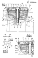
- - Figure 1 shows, in a front sectional view along an axial plane, the silencer in question;
- - Figure 2 shows, in plan view form, one part of the baffle that constitutes an integral part of the silencer in question;
- - Figure 3 shows, viewed in the direction of the arrow A, the part of the baffle depicted in Figure 2;
- - Figure 4 shows, in a second form of embodiment, the detail B in Figure 1.
- With reference to Figures 1, 2 and 3, shown at 1 diagrammatically is the head of a pneumatic gun, in the top part of which there is a
circular indentation 4 that is coaxial and communicating with an annular chamber 1a into which run the extremities of the discharge ducts 2 (destined to place, in accordance with known systems not described herein, the operating cylinder of the gun in communication with the outside atmosphere at the time the operating piston that slides in the inside of the said cylinder adopts afresh the non-operative position) and the extremity of anotherdischarge duct 2a belonging to the (non-illustrated) valve that operates the gun. Furthermore, placed centrally therein theindentation 4 has a threadedhole 3, to which reference will be made in due course. - Into the
indentation 4 is inserted theopen extremity 5a of a casing 5 (of circular section with lateral walls diverging upwards), the other extremity is sealed by acover 6 in whose side there is aslit 7. Because of the said insertion, theextremity 5a communicates directly with the annular chamber 1a. - In the inside surface of the
casing 5 there is a sudden break in the diametrical continuity which gives rise to astep 8 on to which is placed, resting thereon, the outside edge 10a (of a circular development) of a first element 10 (in the centre of which there is a through hole 10b). The said edge is closely enshrouded by the inside surface of thecasing 5. - The surface 10c of the
element 10 turned towards theextremity 5a extends symmetrically with respect to the axis of the hole 10b and is so shaped as to represent a baffle for the compressed gases (flow F) coming from the chamber 1a. For this purpose, the said surface 10c extends in funnel form and is orientated in such a way that the relevant minimum cross section be positioned at a point corresponding to theopen extremity 5a. The said surface 10c and the opposite inside surface of thecasing 5 define afirst chamber 12 which, starting from theextremity 5a and going upwards, increases in volume : this causes, consequently, the expansion of the compressed gases F. - In the form of embodiment depicted in Figure 1, the inside surface of the
casing 5 opposite the said surface 10c is curved so as not to cause vortices which would bring about energy losses and consequential noise in the flow F of compressed gases. The surfaces that laterally delimitate thechamber 12 are, in other words, of a conformation such as to tend to create a laminar flow for the compressed gases F. - The
element 10, close to the outside edge 10a, is provided with a plurality of through holes 13 (parallel to the axis of the hole 10b) which, in one preferred form of embodiment, constitute spaces in atoothing 14 contained in the said edge 10a (Figurs 2-and 3). Theteeth 34 of the said toothing are bent on one and the same side (Figure 3) with respect to a plane perpendicular to the axis of theelement 10, and the reason for this will be clarified below. - Above the
element 10, in the region of thecover 6, there is asecond element 17 that has the circumference thereof closely enshrouded by the inside surface of the casing and is provided with a plurality of transverse through holes and has in the centre a through hole 17a. In one preferred form of embodiment, theelement 17 takes the form of a net. The position of theelement 17 is stabilized with respect to the casing by means of a spacer 16 (constituted by a tubular member coaxial with respect to the holes 10a and 17a) interposed between thesaid element 17 and thesaid element 10. - The facing surfaces of the
elements casing 5, defines asecond chamber 22 which, in the form of embodiment shown in Figure 1, is filled with a filter constituted by , for example, alayer 15 of porous material. In one preferred form of embodiment, thesaid layer 15 consists of two consecutive parts, 15a and 15b, that mate, one with theelement 10 and the other with theelement 17. The porosity of the material inpart 15a is greater than that of the material in thepart 15b, and the reason why this is so will be explained hereinafter. - The
element 17 and the opposite surface of thecover 6 define athird expansion chamber 32. - The locking one to the other of the component parts of the silencer according to the invention, and the locking of the said silencer to the
head 1 of the pneumatic gun, is achieved by inserting, progressively, the shank 19a of abolt 19 into a through hole 6a made centrally in thecover 6, into the hole 17a, into the inside of the spacer 16, and into the hole 10b, so that the said shank engages in thehole 3 to which prior reference has been made, until the head 19b of the bolt abuts with the rim of the aforementioned hole 6a. - A description will now be given of the operation of the pneumatic silencer forming the subject of the invention.
- The compressed gases F coming from the chamber 1a gradually expand as they are passing along the
chamber 12. The expansion of the gases causes a decrease in the velocity thereof and, in consequence, an increase in the gas pressure, which becomes maximum in zone S. - Via the
holes 13, the gases from the zone S invade the chamber 22 (where again they expand). This causes, through the reflection of sound waves, an initial noise loss. - The gases F that pass through the
holes 13 are either totally or partially deviated laterally by thebent teeth 34 and they tend to go into the central zone C of thechamber 22 on account of the fact that the porosity of thepart 15a is greater than that of thepart 15b, the whole purpose of this being to increase the path followed by the gases F in the inside of the chamber where they are slowed down by thelayer 15 of porous material, thereby achieving a noise loss through friction. - Via the
holes 18 drilled in theelement 17, from thechamber 22 the gases invade the chamber 32 (where once again they expand), thereby achieving a further noise loss through the reflection of sound waves. - From the
chamber 32, the gases F are then released, via theslit 7, into the atmosphere where they undergo a definite expansion. This again results in a further noise loss through the reflection of sound waves. - For flows of compressed gases F of a limited capacity, the
layer 15 can be made with a constant porosity, while in the case of capacities that are considerable, thelayer 15 can be constituted by two consecutive parts of different porosity or, by way of an alternative, the variant as per Figure 4 can be utilized. - With reference to Figure 4, at 50 there is a third element (constituted, for example, by a disc containing a plurality of transverse through holes 51) stably positioned in the
chamber 22 since it is closely enshrouded by the inside surface of the casing which, as will be recalled, is of truncated cone shape, and is, furthermore, interposed between two spacers 16a and 16b (Figure 4). Theelement 50 divides thechamber 22 into two parts, namely alower part 22a and anupper part 22b, the former empty and the latter filled with a filter constituted by alayer 55 of porous material which, in turn, consists qf two consecutive parts, 55a and 55b, of which the former mates with theelement 50 and the latter with theelement 17; the porosity of thepart 55a being lesser than that of thepart 55b. - In the
cover 6, according to the form of embodiment depicted in Figure 4, placed laterally there are a number of equidistant slits 7 (eight for example) and, furthermore, starting at the upper part of the cover, there is atailpiece 6b that points downwards and is of a circular development, the diameter thereof being greater than that of the part of the cover that contains theslits 7. The task of thetailpiece 6b is to deviate downwards the compressed gases F which, via theslits 7, from thechamber 32 are released into the atmosphere. - Suitable plates positioned above the cover and fixed thereto at one extremity, while the other extremity is bent downwards in such a way that it be located opposite the corresponding slit, can be provided in place of the
tailpieces 6b. - The compressed gases F that pass through the
holes 13 are deviated laterally by thebent teeth 34 of theelement 10 as they invade thepart 22a of thechamber 22. In this way, they are deviated out of preference towards the inside of thepart 22a. The saidpart 22a constitutes an expansion chamber for the gases F coming from thehole 13 and this is optimal since the passage of the gases into the part 22b.is achieved crossing the full number of holes 51 with which theelement 50 is provided. - In this way, the damping action of the
part 55a of the layer 55 (the one of a lesser porosity) takes place in the most critical zone in the path followed by the gases F across thelayer 55, that is to say, in the region of the discharge orifices of the holes 51 where the velocity of the gases is maximum. - The gases F from the
part 22b (where they expand and, at the same time, are slowed down) invade, via theholes 18, thechamber 32 and pass from there, via theslits 7, into the atmosphere. As the gases F pass through theslits 7, they are deviated downwards by the tail piece 6a and thus the source of the noise (namely the gases F released into the atmosphere) tends to be kept away from the ears of the operator. - The silencer, in the form of embodiment envisaged in Figure.4, deadens the discharge noise because of noise being lost through the reflection of sound waves (with the gases F passing through the
holes - Since the foregoing description has been given purely as an unlimited example, all possible variants in respect of the constructional details (for example, the taper of the inside surface of the
casing 5 could be used, in place of thestep 8, to support the element 10) are understood to fall within the technical solution as outlined above and claimed hereinafter.
Claims (13)
1. A silencer for pneumatic equipment, comprising a casing 5, open at one extremity 5a and closed at the other extremity by means of a cover 6 in which there is at least one slit 7, that can be locked in a removable fashion to the body 1 of the compressed gas device with which it is used, in such a way that the open extremity 5a communicates directly with the duct 2 for the discharge of the gases in the said device, there being in the said casing, starting at the open extremity and going towards the cover, closely enshrouded circumferentially by the inside surface of the casing, a first element 10, a filter 15 or 55, and a second element 17, of which the first element defines, in cooperation with the relevant part of the inside surface of the casing 5, a first expansion chamber 12 for the compressed gases, as well as, in cooperation with the second element 17 and with the strip of the inside surface of the casing delimitated by the said elements, a second compressed gas expansion chamber 22 that contains the said filter, while the second element defines, furthermore, in cooperation with the cover 6, a third expansion chamber 32 for the compressed gases; both the said first element 10 and the said second element 17 being provided with a plurality of through holes, 13 and 18, respectively, to render the first chamber communicating with the second, and the second chamber communicating with the third, respectively.
2. A silencer according to Claim 1, wherein the surface 10c of the said first element 10 that points towards the open extremity 5a of the casing 5 is of a funnel conformation and is so orientated as to have the minimum area thereof positioned in the region of the said open extremity 5a.
3. A silencer according to Claim 1, wherein the through holes 13 in the first element 10 constitute spaces in a toothing 14 contained in the edge of the said first element closely enshrouded by the inside surface of the casing.
4. A silencer according to Claim 3, wherein the teeth 34 of the said toothing 14 are all bent on one and the same side with respect to a plane perpendicular to the axis of the first element.
5. "A silencer according to Claim 1, wherein the said filter is constituted by a layer of porous material.
6. A silencer according to Claim 5, wherein the said layer of porous material completely fills the aforementioned second expansion chamber 22 and is constituted by at least two consecutive parts, namely a first part 15a or 55a and a second part 15b or 55b, that mate with the first and the second element, respectively, the first part having a porosity greater than that of the second part.
7. A silencer according to Claim 5, wherein a third element 50 whose periphery is closely and stably enshrouded by the strip of the inside surface of the casing 5 existing between the said first element 10 and the said second element 17, is destined to divide the said second expansion chamber 22 into two parts, namely a lower part 22a and an upper part 22b, the former empty and the latter filled with the said porous material 55, the said third element 50 containing a plurality of through holes 51 for communication between the said lower and upper parts of the second chamber.
8. A silencer according to Claim 7, wherein the said layer of porous material 55 is constituted by at least two consecutive parts, namely a first part 55a and a second part 55b, that mate with the third element and with the second element, respectively, the first part having a porosity lesser than that of the second part.
9. A silencer according to Claim 1, wherein starting at the edge of the upper part of the cover 6 there is a tail piece 6b that extends externally with respect to the said cover and points towards the open extremity of the casing, in a position opposite the said slit 7.
10. A silencer according to Claim 1, wherein the locking in a removable fashion of the silencer to the body of the device with which it is used, is achieved by at least one bolt, the shank of which passes progressively across the through holes in the cover, in the second element and in the first element in order to then engage with a corresponding threaded housing made in the said body, while the head of the bolt abuts with the said cover, the silencer comprising a-tubular member 16, through which the shank 19a of the bolt 19 passes freely, interposed between the opposite surfaces of the said first and second element.
11. A silencer according to Claim 1, wherein the said second element 17 takes the form of a net.
12. A silencer according to Claim 2, wherein the inside surface of the casing that delimitates laterally, in cooperation with the opposite surface of the first element, the first expansion chamber 12, is curved so as not to cause vortices in the flow of the compressed gases contained in the said first chamber.
13. A silencer according to Claim 7, wherein the locking in a removable fashion of the silencer to the body of the device with which it is used, is achieved by at least one bolt, the shank of which passes across through holes in the cover, in the second element, in the third element and in the first element in order to then engage with a corresponding threaded housing made in the said body, while the head of the bolt abuts with the said cover, the silencer comprising two tubular members, 16a and 16b, through which the shank 19a of the bolt 19 passes freely, one of which interposed between the opposite surfaces of the said first and third element, and the other interposed between the opposite surfaces of the said third and second element.
Applications Claiming Priority (2)
| Application Number | Priority Date | Filing Date | Title |
|---|---|---|---|
| IT480581U | 1981-03-31 | ||
| ITBO1981U4805U IT8104805U1 (en) | 1981-03-31 | 1981-03-31 | EXHAUST SILENCER ESPECIALLY FOR GUNS AND PNEUMATIC EQUIPMENT |
Publications (2)
| Publication Number | Publication Date |
|---|---|
| EP0062009A2 true EP0062009A2 (en) | 1982-10-06 |
| EP0062009A3 EP0062009A3 (en) | 1983-02-23 |
Family
ID=11113994
Family Applications (1)
| Application Number | Title | Priority Date | Filing Date |
|---|---|---|---|
| EP82830052A Withdrawn EP0062009A3 (en) | 1981-03-31 | 1982-03-10 | A silencer for pneumatic equipment |
Country Status (4)
| Country | Link |
|---|---|
| US (1) | US4424883A (en) |
| EP (1) | EP0062009A3 (en) |
| ES (1) | ES264193Y (en) |
| IT (1) | IT8104805U1 (en) |
Cited By (5)
| Publication number | Priority date | Publication date | Assignee | Title |
|---|---|---|---|---|
| EP0147262A1 (en) * | 1983-11-10 | 1985-07-03 | CHARBONNAGES DE FRANCE, Etablissement public dit: | Sound-attenuating housing for pneumatic drills |
| EP0446726A1 (en) * | 1990-03-10 | 1991-09-18 | Miksa Marton Dualflex Company Ltd. | Silencer device |
| AT393982B (en) * | 1987-10-01 | 1992-01-10 | Paslode Gmbh | PNEUMATIC NAILER |
| EP0720892A1 (en) * | 1995-01-04 | 1996-07-10 | Joh. Friedrich Behrens AG | Fastener driving tool |
| DE102008028938A1 (en) * | 2008-03-28 | 2009-10-01 | TRANMAX MACHINERY Co., Ltd., Taiping | Pneumatic tool with noise reduction function |
Families Citing this family (33)
| Publication number | Priority date | Publication date | Assignee | Title |
|---|---|---|---|---|
| JPS6047869U (en) * | 1983-09-09 | 1985-04-04 | 株式会社 共立 | Silence filter |
| DE3634579A1 (en) * | 1986-10-10 | 1988-04-21 | Paul Schmidt | PNEUMATIC DRILL DRILL |
| JPS6472727A (en) * | 1987-09-14 | 1989-03-17 | Terumo Corp | Automatic hemomanometer |
| US5097924A (en) * | 1988-06-08 | 1992-03-24 | Mcneil (Ohio) Corporation | Muffler for a compressed air driven motor |
| US5731556A (en) * | 1996-09-30 | 1998-03-24 | Ingersoll-Rand Company | Muffler for pneumatic device |
| US6202785B1 (en) | 1999-06-02 | 2001-03-20 | 3M Innovative Properties Company | Muffler with acoustic absorption insert for limited clearance pneumatic device applications |
| US6089346A (en) * | 1999-06-02 | 2000-07-18 | 3M Innovative Properties Company | Muffler with acoustic barrier material for limited clearance pneumatic device applications |
| US6161646A (en) * | 1999-08-17 | 2000-12-19 | Eaton Aeroquip Inc. | Turbo-generator exhaust noise silencer |
| US6325844B1 (en) * | 2000-05-31 | 2001-12-04 | Florida Pneumatic Manufacturing Corporation | Filter and muffler device for vacuum mechanism |
| US7223266B2 (en) * | 2003-02-04 | 2007-05-29 | Cardiodex Ltd. | Methods and apparatus for hemostasis following arterial catheterization |
| US6935460B2 (en) * | 2003-05-21 | 2005-08-30 | Airsep Corporation | Noise muffler for oxygen concentrator |
| JP4367918B2 (en) * | 2004-01-09 | 2009-11-18 | 本田技研工業株式会社 | Small engine exhaust system |
| DE102005007290B3 (en) * | 2005-02-17 | 2006-07-27 | Itw-Befestigungssysteme Gmbh | Gas flow sound damper for use in e.g. hand-operated driving tool for nails, has cover with number of fibers or filament bundles fixed with end at cover, which has gas emanation opening lying transverse to exhaust gas inflow direction |
| US7530427B2 (en) * | 2006-06-12 | 2009-05-12 | Briggs & Stratton Corporation | Exhaust deflector for a muffler |
| US7530428B2 (en) * | 2006-06-12 | 2009-05-12 | Briggs & Stratton Corporation | Exhaust deflector for a muffler |
| US20080099277A1 (en) * | 2006-10-30 | 2008-05-01 | Basso Industry Corp. | Muffler for pneumatic tools |
| US7900316B2 (en) * | 2007-01-30 | 2011-03-08 | Bissell Homecare Inc. | Filter for a vacuum cleaner |
| DE202007006627U1 (en) * | 2007-05-09 | 2007-07-19 | Knorr-Bremse Systeme für Nutzfahrzeuge GmbH | Sound absorber for pneumatic device of vehicle, has housing arranged between inlet opening and outlet opening, and layer of fibrous material arranged between cartridge and pot casing |
| US8047327B2 (en) * | 2008-01-04 | 2011-11-01 | Audeval Solutions Inc. | Muffler for pneumatic handheld tool |
| US7878299B2 (en) * | 2008-02-13 | 2011-02-01 | Geyer Iii Robert E | Silencer apparatus with disposable silencer cartridge unit |
| TWI387514B (en) * | 2010-09-20 | 2013-03-01 | 鑽全實業股份有限公司 | High pressure nail gun that eliminates exhaust noise |
| DE102012112069A1 (en) * | 2012-12-11 | 2014-06-12 | Hella Kgaa Hueck & Co. | pump |
| KR102184253B1 (en) | 2013-10-08 | 2020-11-30 | 데이코 아이피 홀딩스 엘엘시 | Noise attenuation in a check valve unit or apparatus for producing vacuum |
| BR112016013075B1 (en) | 2013-12-09 | 2022-04-19 | Dayco Ip Holdings, Llc | NOISE Attenuation UNIT AND FLUID FLOW SYSTEM INSIDE AN INTERNAL COMBUSTION ENGINE |
| US10107240B2 (en) | 2014-04-04 | 2018-10-23 | Dayco Ip Holdings, Llc | Check valves and Venturi devices having the same |
| EP3148852B1 (en) | 2014-05-30 | 2021-03-24 | Dayco IP Holdings, LLC | Vacuum creation system having an ejector, pneumatic control valve and optionally an aspirator |
| US9382826B1 (en) | 2015-01-09 | 2016-07-05 | Dayco Ip Holdings, Llc | Noise attenuating member for noise attenuating units in engines |
| KR102255542B1 (en) | 2015-01-09 | 2021-05-24 | 데이코 아이피 홀딩스 엘엘시 | Crankcase ventilating evacuator |
| BR112017022110B1 (en) | 2015-04-13 | 2023-03-21 | Dayco Ip Holdings, Llc | DEVICES FOR PRODUCING A VACUUM USING THE VENTURI EFFECT AND SYSTEM INCLUDING A DEVICE FOR PRODUCING A VACUUM USING THE VENTURI EFFECT |
| US10422351B2 (en) | 2015-07-17 | 2019-09-24 | Dayco Ip Holdings, Llc | Devices for producing vacuum using the venturi effect having a plurality of subpassageways and motive exits in the motive section |
| WO2017075390A1 (en) | 2015-10-28 | 2017-05-04 | Dayco IP Holding, LLC | Venturi devices resistant to ice formation for producing vacuum from crankcase gases |
| DE102017122215A1 (en) * | 2017-09-26 | 2019-03-28 | Knorr-Bremse Systeme für Nutzfahrzeuge GmbH | Silencer for compressed air systems and a method for its production |
| US11371404B2 (en) * | 2019-08-13 | 2022-06-28 | Herbert Anderson | Engine muffler apparatus |
Family Cites Families (8)
| Publication number | Priority date | Publication date | Assignee | Title |
|---|---|---|---|---|
| US226905A (en) * | 1880-04-27 | Noise-quieting nozzle | ||
| GB191409414A (en) * | 1900-01-01 | |||
| GB235929A (en) * | 1924-02-28 | 1925-06-29 | Nicholas Straussler | Improvements in or relating to silencers for gaseous currents |
| NL7104328A (en) * | 1971-03-31 | 1972-10-03 | ||
| CA980258A (en) * | 1973-06-14 | 1975-12-23 | Sherritt Gordon Mines Limited | Exhaust gas silencer |
| DE2601483C3 (en) * | 1976-01-16 | 1980-02-28 | Armaturen- Und Autogengeraetefabrik Ewo Hermann Holzapfel Kg, 7000 Stuttgart | silencer |
| US4109753A (en) * | 1976-11-19 | 1978-08-29 | Midas-International Corporation | Muffler assembly |
| DE2933105C2 (en) * | 1979-08-16 | 1983-12-15 | Robert Bosch Gmbh, 7000 Stuttgart | silencer |
-
1981
- 1981-03-31 IT ITBO1981U4805U patent/IT8104805U1/en unknown
-
1982
- 1982-03-09 US US06/356,446 patent/US4424883A/en not_active Expired - Fee Related
- 1982-03-10 EP EP82830052A patent/EP0062009A3/en not_active Withdrawn
- 1982-03-29 ES ES1982264193U patent/ES264193Y/en not_active Expired
Cited By (5)
| Publication number | Priority date | Publication date | Assignee | Title |
|---|---|---|---|---|
| EP0147262A1 (en) * | 1983-11-10 | 1985-07-03 | CHARBONNAGES DE FRANCE, Etablissement public dit: | Sound-attenuating housing for pneumatic drills |
| AT393982B (en) * | 1987-10-01 | 1992-01-10 | Paslode Gmbh | PNEUMATIC NAILER |
| EP0446726A1 (en) * | 1990-03-10 | 1991-09-18 | Miksa Marton Dualflex Company Ltd. | Silencer device |
| EP0720892A1 (en) * | 1995-01-04 | 1996-07-10 | Joh. Friedrich Behrens AG | Fastener driving tool |
| DE102008028938A1 (en) * | 2008-03-28 | 2009-10-01 | TRANMAX MACHINERY Co., Ltd., Taiping | Pneumatic tool with noise reduction function |
Also Published As
| Publication number | Publication date |
|---|---|
| ES264193Y (en) | 1983-05-16 |
| EP0062009A3 (en) | 1983-02-23 |
| IT8104805V0 (en) | 1981-03-31 |
| IT8104805U1 (en) | 1982-10-01 |
| ES264193U (en) | 1982-11-16 |
| US4424883A (en) | 1984-01-10 |
Similar Documents
| Publication | Publication Date | Title |
|---|---|---|
| EP0062009A2 (en) | A silencer for pneumatic equipment | |
| US5029512A (en) | Firearm muzzle silencer | |
| US4267899A (en) | Muffler assembly | |
| EP0219218B1 (en) | Muffler | |
| CA1092984A (en) | Spark arrester and engine muffler | |
| US4111278A (en) | Discharge muffler | |
| US3941206A (en) | Noise attenuating snubber | |
| US3680659A (en) | Noise muffler having a unique pressure safety valve | |
| US4550799A (en) | Muffler for exhaust gases | |
| US5200582A (en) | Passive muffler for low pass frequencies | |
| US5101930A (en) | Hydraulic elevator muffler | |
| US3688868A (en) | Expansion chambered, fail-safe muffler | |
| US4177875A (en) | Muffler for internal combustion engine | |
| US2189424A (en) | Surge filter for pulsating gases | |
| US2329101A (en) | Apparatus for silencing pulsating gas streams and separating particles therefrom | |
| US3679024A (en) | Muffler | |
| KR102000858B1 (en) | silencer | |
| US3117650A (en) | Silencing element for exhaust gas conduit | |
| US4953659A (en) | Fluid blow-off muffler | |
| US3491850A (en) | Sound silencing apparatus | |
| CZ20022795A3 (en) | Sound damper for compressors | |
| SU1574918A1 (en) | Fan noise silencer | |
| KR200234117Y1 (en) | silencer | |
| US3715010A (en) | Multiple collimator muffler | |
| BE1030618A1 (en) | Intake silencer for a volumetric compressor and volumetric compressor equipped with it |
Legal Events
| Date | Code | Title | Description |
|---|---|---|---|
| PUAI | Public reference made under article 153(3) epc to a published international application that has entered the european phase |
Free format text: ORIGINAL CODE: 0009012 |
|
| AK | Designated contracting states |
Designated state(s): AT BE DE FR GB NL SE |
|
| PUAL | Search report despatched |
Free format text: ORIGINAL CODE: 0009013 |
|
| AK | Designated contracting states |
Designated state(s): AT BE DE FR GB NL SE |
|
| STAA | Information on the status of an ep patent application or granted ep patent |
Free format text: STATUS: THE APPLICATION IS DEEMED TO BE WITHDRAWN |
|
| 18D | Application deemed to be withdrawn |
Effective date: 19840204 |
|
| RIN1 | Information on inventor provided before grant (corrected) |
Inventor name: MUSIANI, FRANCO |