EP0061159A2 - Umkehrbare Kreiselpumpe mit gleicher Leistung in beiden Drehrichtungen - Google Patents
Umkehrbare Kreiselpumpe mit gleicher Leistung in beiden Drehrichtungen Download PDFInfo
- Publication number
- EP0061159A2 EP0061159A2 EP82102236A EP82102236A EP0061159A2 EP 0061159 A2 EP0061159 A2 EP 0061159A2 EP 82102236 A EP82102236 A EP 82102236A EP 82102236 A EP82102236 A EP 82102236A EP 0061159 A2 EP0061159 A2 EP 0061159A2
- Authority
- EP
- European Patent Office
- Prior art keywords
- impeller
- assembly
- flow
- reversible
- fluid
- Prior art date
- Legal status (The legal status is an assumption and is not a legal conclusion. Google has not performed a legal analysis and makes no representation as to the accuracy of the status listed.)
- Withdrawn
Links
Images

Classifications
-
- F—MECHANICAL ENGINEERING; LIGHTING; HEATING; WEAPONS; BLASTING
- F04—POSITIVE - DISPLACEMENT MACHINES FOR LIQUIDS; PUMPS FOR LIQUIDS OR ELASTIC FLUIDS
- F04D—NON-POSITIVE-DISPLACEMENT PUMPS
- F04D1/00—Radial-flow pumps, e.g. centrifugal pumps; Helico-centrifugal pumps
- F04D1/04—Helico-centrifugal pumps
-
- F—MECHANICAL ENGINEERING; LIGHTING; HEATING; WEAPONS; BLASTING
- F04—POSITIVE - DISPLACEMENT MACHINES FOR LIQUIDS; PUMPS FOR LIQUIDS OR ELASTIC FLUIDS
- F04D—NON-POSITIVE-DISPLACEMENT PUMPS
- F04D29/00—Details, component parts, or accessories
- F04D29/18—Rotors
- F04D29/22—Rotors specially for centrifugal pumps
- F04D29/2261—Rotors specially for centrifugal pumps with special measures
- F04D29/2283—Rotors specially for centrifugal pumps with special measures for reverse pumping action
Definitions
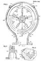
- the invention relates to a reversible centrifugal pump and more particularly to an improved reversible centrifugal pump wherein the centrifugal impeller contains radially shaped impeller vanes with gradually changing vane angles on both identical working sides so as to provide identical hydraulic performance in either rotational direction.
- a centrifugal pump which is particularly characterized by a fully concentric case designed to afford uniform flow areas between the vanes and an exit flow splitter directing the flow through the impeller into the concentric case, thereby to eliminate flow separation at the impeller exit and controlling required exit area.
- the pump is also characterized by a reversible enclosed cast centrifugal impeller containing radial impeller vanes shaped with a gradual change in the vane angle on both identical working sides for identical hydraulic performance in either rotational direction.
- Fluid flow enters into the impeller eye and careful rounding of the inlet edges to an airfoil shape, combined with a small vane thickness reduces cavitation.
- a shroud is located in the casing behind the impeller on the side opposite the inlet of the impeller.
- Axial thrust balancing passages extending through the impeller are used to reduce the pressure area behind the back shroud.
- the splitter angle is made the same as the absolute exit angle of the fluid leaving the impeller, thereby to avoid shock losses.
- the pumping chamber piece 110 in which is formed a volute pumping chamber communicates with the inlet passage 13, via an inlet eye 19 and is secured to walls 14a, 14b by means of a plurality of fastening studs as exemplified in fastening studs 22a, 22b.
- a corresponding plurality of nuts 24a, 24b secure washers 26a, 26b to side walls 14a, 14b so as to provide a tight sealing arrangement.
- the rotating shaft mounting piece 12 has a mounting flange 30 which is secured to the pumping chamber piece 110 by means of a plurality of studs as exemplified by fastening stud 22c.
- a nut 24c for each stud 22c affixes a washer 26c in a tight sealing arrangement to the mounting flange 30.
- a reversible impeller 32 having a plurality of impeller vanes or pumping vanes 34a, 34b which are spaced circumferentially and extend radially, and a hub 36, are fastened to a threaded end portion 38 of a drive shaft 28 by means of a securing nut 40.
- a tapered median section 42 of the drive shaft 28, adjacent a threaded end portion 38 is inserted into a correspondingly tapered receiving opening 44 on hub 36 in a tight fitting relationship.
- the drive shaft 28 is engaged by means of a power source, and the contact between the drive shaft 28 and the impeller assembly 32 is provided by a plurality of key elements 46 as well as the tapered end section 42 which enable the impeller assembly 32 to be rotated simultaneously with the drive shaft 28.
- the rotational motion of the impeller 32 acts to draw water through the inlet passage 13 into a receiving chamber 50 of the casing portion 11.
- the receiving chamber 50 has symmetrical walls 52a, 52b which act to provide an evenly distributed radial load regardless of the rotational direction of the impeller assembly 32.
- a very small clearance area 54 is provided for between a case ring 56 and an impeller flange 58 so as to enable the impeller assembly 32 to rotate freely while preventing large amounts of water from entering a cavity or a pocket portion 60.
- the rotational motion of the impeller 32 creates a substantial pressure differential between the relatively high pressure maintained in the receiving chamber 50 as compared to the relatively low pressure maintained in the inlet passage 13.
- the pressure differential caused by the rotational motion of the impeller 32 tends to load the drive shaft 28 along its axis toward the inlet passage 13 resulting in increased force being applied against the drive shaft 28 by a back shroud 61.
- a plurality of threaded axial thrust balancing passageways exemplified by threaded passageway 62 extend completely through the impeller 32 from the inlet side of the back side.
- the threaded passageway 62 also serves to prevent the build up of fluid within the pocket portion 60 by providing means for passing fluid under high pressure in pocket portion 60 into the inlet passage 13.
- the operator may bleed off entrapped air pockets by selectively opening one or more of the plugs 18a.
- a seal assembly 64 is positioned around the circumference of the drive shaft 28 so as to prevent the loss of any fluid along the outer surface of the drive shaft 28.
- the seal assembly 64 is affixed to the back shroud 61 which in turn is mounted to the pumping chamber piece 110 by means of a plurality of securing means such as a flat head screw 68.
- the insertion of the tapered end section 42 of drive shaft 28 into the corresponding receiving opening 44 of impeller hub 36 insures a snug fit of the parts.
- the suction piece 11 is first removed, thereby exposing the impeller nut 40.
- an impeller pulling means (not shown) may be employed which engages against an end face 28A on the end of the shaft 28.
- the impeller pulling means may be of the type wherein threaded rods are adapted to engage the threaded passageways 62.
- the casing portion 11 is fully symmetrical about a horizontal axis or plane 69a and a vertical axis or plane 69b, both of which axes or planes are shown in Fig. 2 in dashed lines and designated by the corresponding reference numerals 69a and 69b.
- the reversible impeller 32 consists of a plurality of circumferentially spread radially extending pumping vanes 34 mounted to the hub 36. Each of the impellers is formed with a carefully rounded inlet edge 70 so as to describe an air foil shape. The thickness of each vane 34 is relatively narrow so that the dimensional extent is shown at 70a.
- the rounded inlet edges 70 provide a gradual change in the vane angle and each side of each vane, shown as 70b and 70c, respectively, form identical working sides.
- the air foil shape terminates in a trailing edge 70d at the outer periphery of the impeller.
- the air foil shape and the relatively small vane thickness 70a it will be apparent that cavitation will be substantially reduced.
- There should be a sufficient number of vanes 34 so as to provide good guidance to the fluid passing through the impeller and to keep the fluid pressure on each individual vane 34 relatively low.
- a pumping chamber 74 formed within the pumping chamber piece 110 and centrally disposed on the axes or planes 69a, 69b, is bounded in part by a wall surface 76 formed by one side of a dual flow splitter shown generally at 78 and which dual flow splitter 78 is triangular in cross-sectional configuration.
- the dual flow splitter 78 has side wall surfaces 80 and 82 which intersect the wall surface 76 and extend downwardly, using the orientation of Fig. 2, to a common apex 84 located on the vertical plane 69b. The positioning of the dual flow splitter 78 directs the flow into the throats 90 and 92 regardless of the rotational direction of the impeller 32.
- the surface 80 of the dual flow splitter 78 is spaced from an adjoining wall of the casing portion 11, as shown at 86, and the surface 82 of the dual flow splitter 78 is likewise spaced from an adjoining wall of the casing 11, as shown at 88, thereby to form a pair of throats 90 and 92 symmetrically disposed on opposite sides of the vertical plane 69b.
- the throats 90 and 92 merge into a common discharge opening 94 extending through a discharge flange 96.
- the angle formed by the dual flow splitter 78 is generally the same as the absolute exit angle of the fluid leaving the impeller 32.
- the ratio of the relative flow ar-a between the impeller vanes 34 and the throat portions 90 and 92 control the head, quantity and power characteristics of a particular pump.
- a pair of recessed portions 98a, 98b, located in the dual flow splitter 78 are separated by means of a divider section 100.
- Fig. 4 illustrates the means used to reduce the shock losses resulting from the force of the fluid exiting the impeller 32 and striking wall 86.
- the symmetrically shaped dual flow divider 78 is positioned in such a manner so as to form an angle with throat area 90 which is the same as the absolute exit angle of the fluid leaving the impeller 32.
Landscapes
- Engineering & Computer Science (AREA)
- Mechanical Engineering (AREA)
- General Engineering & Computer Science (AREA)
- Structures Of Non-Positive Displacement Pumps (AREA)
Applications Claiming Priority (2)
| Application Number | Priority Date | Filing Date | Title |
|---|---|---|---|
| US24612381A | 1981-03-20 | 1981-03-20 | |
| US246123 | 1981-03-20 |
Publications (2)
| Publication Number | Publication Date |
|---|---|
| EP0061159A2 true EP0061159A2 (de) | 1982-09-29 |
| EP0061159A3 EP0061159A3 (de) | 1983-04-20 |
Family
ID=22929395
Family Applications (1)
| Application Number | Title | Priority Date | Filing Date |
|---|---|---|---|
| EP82102236A Withdrawn EP0061159A3 (de) | 1981-03-20 | 1982-03-18 | Umkehrbare Kreiselpumpe mit gleicher Leistung in beiden Drehrichtungen |
Country Status (1)
| Country | Link |
|---|---|
| EP (1) | EP0061159A3 (de) |
Cited By (5)
| Publication number | Priority date | Publication date | Assignee | Title |
|---|---|---|---|---|
| DE4203391A1 (de) * | 1992-02-06 | 1993-08-12 | Schaeffler Waelzlager Kg | Dichtungsanordnung fuer eine wasserpumpe einer brennkraftmaschine |
| EP0664397A1 (de) * | 1994-01-24 | 1995-07-26 | JUWEL AQUARIUM GmbH & Co. KG | Impellerpumpe |
| WO1997021927A1 (en) * | 1995-12-14 | 1997-06-19 | Warman International Limited | Centrifugal pump |
| EP0893601A3 (de) * | 1997-07-25 | 2000-03-01 | Uraca Pumpenfabrik Gmbh & Co. Kg | Pumpenanordnung mit einer Kolbenpumpe und einer Boosterpumpe |
| CN103591046A (zh) * | 2013-11-12 | 2014-02-19 | 大连理工大学 | 一种多源约束下的大功率屏蔽电机核主泵高效水力模型 |
Family Cites Families (3)
| Publication number | Priority date | Publication date | Assignee | Title |
|---|---|---|---|---|
| US2291478A (en) * | 1939-08-12 | 1942-07-28 | Bour Harry E La | Centrifugal pump |
| LU46076A1 (de) * | 1963-05-15 | 1972-01-01 | ||
| FR2281045A7 (fr) * | 1974-07-30 | 1976-02-27 | Bosch Siemens Hausgeraete | Pompe centrifuge equipee d'un moteur d'entrainement |
-
1982
- 1982-03-18 EP EP82102236A patent/EP0061159A3/de not_active Withdrawn
Cited By (5)
| Publication number | Priority date | Publication date | Assignee | Title |
|---|---|---|---|---|
| DE4203391A1 (de) * | 1992-02-06 | 1993-08-12 | Schaeffler Waelzlager Kg | Dichtungsanordnung fuer eine wasserpumpe einer brennkraftmaschine |
| EP0664397A1 (de) * | 1994-01-24 | 1995-07-26 | JUWEL AQUARIUM GmbH & Co. KG | Impellerpumpe |
| WO1997021927A1 (en) * | 1995-12-14 | 1997-06-19 | Warman International Limited | Centrifugal pump |
| EP0893601A3 (de) * | 1997-07-25 | 2000-03-01 | Uraca Pumpenfabrik Gmbh & Co. Kg | Pumpenanordnung mit einer Kolbenpumpe und einer Boosterpumpe |
| CN103591046A (zh) * | 2013-11-12 | 2014-02-19 | 大连理工大学 | 一种多源约束下的大功率屏蔽电机核主泵高效水力模型 |
Also Published As
| Publication number | Publication date |
|---|---|
| EP0061159A3 (de) | 1983-04-20 |
Similar Documents
| Publication | Publication Date | Title |
|---|---|---|
| US5320482A (en) | Method and apparatus for reducing axial thrust in centrifugal pumps | |
| CN108350907B (zh) | 低气蚀叶轮以及泵 | |
| EP0011982B1 (de) | Drehende Seitenkanalmaschine | |
| US3244109A (en) | Centrifugal pumps | |
| US4212585A (en) | Centrifugal compressor | |
| US3213794A (en) | Centrifugal pump with gas separation means | |
| US3171353A (en) | Centrifugal fluid pump | |
| CA1219245A (en) | Single-stage, multiple outlet centrifugal blower | |
| US3804335A (en) | Vaneless supersonic nozzle | |
| US3644055A (en) | Fluid-motion apparatus | |
| US2933238A (en) | Axial flow compressors incorporating boundary layer control | |
| US2597510A (en) | Blade element for rotary fluid machines | |
| US3746467A (en) | Toothed shroud centrifugal impeller | |
| US3324799A (en) | Radial staging for reentry compressor | |
| US3013501A (en) | Centrifugal impeller | |
| US3414188A (en) | Fan having hollow blades | |
| EP0061159A2 (de) | Umkehrbare Kreiselpumpe mit gleicher Leistung in beiden Drehrichtungen | |
| US3506373A (en) | Hydrodynamically balanced centrifugal impeller | |
| KR101776883B1 (ko) | 압력발생날개가 부가된 임펠러를 포함하는 원심펌프 | |
| US5257910A (en) | Centrifugal pump impeller with a low specific speed of rotation | |
| US4422832A (en) | Liquid ring pump with vanes in liquid ring | |
| US2003350A (en) | Pump | |
| US2543923A (en) | Radial air compressor | |
| CN105683582A (zh) | 用于前掠切向流压缩机的扩散器 | |
| US4655680A (en) | Continuous blade axial-flow friction drag pump |
Legal Events
| Date | Code | Title | Description |
|---|---|---|---|
| PUAI | Public reference made under article 153(3) epc to a published international application that has entered the european phase |
Free format text: ORIGINAL CODE: 0009012 |
|
| AK | Designated contracting states |
Designated state(s): AT BE DE FR GB IT NL SE |
|
| PUAL | Search report despatched |
Free format text: ORIGINAL CODE: 0009013 |
|
| AK | Designated contracting states |
Designated state(s): AT BE DE FR GB IT NL SE |
|
| STAA | Information on the status of an ep patent application or granted ep patent |
Free format text: STATUS: THE APPLICATION IS DEEMED TO BE WITHDRAWN |
|
| 18D | Application deemed to be withdrawn |
Effective date: 19840327 |
|
| RIN1 | Information on inventor provided before grant (corrected) |
Inventor name: LEGAULT, JOHN FRANCIS |