EP0061148B1 - Electronic liquid level gauge - Google Patents
Electronic liquid level gauge Download PDFInfo
- Publication number
- EP0061148B1 EP0061148B1 EP82102185A EP82102185A EP0061148B1 EP 0061148 B1 EP0061148 B1 EP 0061148B1 EP 82102185 A EP82102185 A EP 82102185A EP 82102185 A EP82102185 A EP 82102185A EP 0061148 B1 EP0061148 B1 EP 0061148B1
- Authority
- EP
- European Patent Office
- Prior art keywords
- oscillator
- counter
- divider
- pulses
- pulse
- Prior art date
- Legal status (The legal status is an assumption and is not a legal conclusion. Google has not performed a legal analysis and makes no representation as to the accuracy of the status listed.)
- Expired
Links
- 239000007788 liquid Substances 0.000 title claims description 65
- 230000004044 response Effects 0.000 claims description 8
- 230000001939 inductive effect Effects 0.000 claims description 7
- 230000001960 triggered effect Effects 0.000 claims description 7
- 239000000446 fuel Substances 0.000 description 11
- 239000003990 capacitor Substances 0.000 description 6
- 238000005259 measurement Methods 0.000 description 6
- 238000010586 diagram Methods 0.000 description 3
- 230000008859 change Effects 0.000 description 2
- 230000001419 dependent effect Effects 0.000 description 2
- 238000005070 sampling Methods 0.000 description 2
- 239000000654 additive Substances 0.000 description 1
- 238000010276 construction Methods 0.000 description 1
- 230000006870 function Effects 0.000 description 1
- 239000010763 heavy fuel oil Substances 0.000 description 1
- 238000000034 method Methods 0.000 description 1
- 238000012986 modification Methods 0.000 description 1
- 230000004048 modification Effects 0.000 description 1
- 239000003208 petroleum Substances 0.000 description 1
- 230000001172 regenerating effect Effects 0.000 description 1
- 102220028659 rs1801496 Human genes 0.000 description 1
- 239000000523 sample Substances 0.000 description 1
Images
Classifications
-
- G—PHYSICS
- G01—MEASURING; TESTING
- G01F—MEASURING VOLUME, VOLUME FLOW, MASS FLOW OR LIQUID LEVEL; METERING BY VOLUME
- G01F23/00—Indicating or measuring liquid level or level of fluent solid material, e.g. indicating in terms of volume or indicating by means of an alarm
- G01F23/22—Indicating or measuring liquid level or level of fluent solid material, e.g. indicating in terms of volume or indicating by means of an alarm by measuring physical variables, other than linear dimensions, pressure or weight, dependent on the level to be measured, e.g. by difference of heat transfer of steam or water
- G01F23/26—Indicating or measuring liquid level or level of fluent solid material, e.g. indicating in terms of volume or indicating by means of an alarm by measuring physical variables, other than linear dimensions, pressure or weight, dependent on the level to be measured, e.g. by difference of heat transfer of steam or water by measuring variations of capacity or inductance of capacitors or inductors arising from the presence of liquid or fluent solid material in the electric or electromagnetic fields
- G01F23/263—Indicating or measuring liquid level or level of fluent solid material, e.g. indicating in terms of volume or indicating by means of an alarm by measuring physical variables, other than linear dimensions, pressure or weight, dependent on the level to be measured, e.g. by difference of heat transfer of steam or water by measuring variations of capacity or inductance of capacitors or inductors arising from the presence of liquid or fluent solid material in the electric or electromagnetic fields by measuring variations in capacitance of capacitors
Definitions
- This invention relates to an electronic liquid level gauge fnr measuring the level of a liquid contained in a vessel and, more particularly, to such an electronic liquid level gauge employing an electrode pair having two electrode plates faced in spaced-parallel relation to each other and immersed in the liquid, the electrode pair having an electrostatic capacity determinative on the liquid level.
- Another electrode pair has been employed in addition to the former electrode pair.
- the latter electrode pair has two electrode plates faced in spaced-parallel relation to each other and immersed in the liquid, the electrode pair having an electrostatic capacity determinative on the specific inductive capacity of the liquid.
- the oscillator pulse repetition period T i which is represented by B 1 C 1 , is converted into a binary number by a repetition period detector.
- the detector output is coupled to a subtractor which subtracts a constant B 1 .C 1 from the repetition rate binary value and provides a difference B 1 . (C 1 -C 0 ).
- the latter electrode pair is associated with an oscillator which generates oscillator pulses of a repetition period T 2 directly proportional to the electrostatic capacity C 2 of the latter electrode pair.
- the oscillator pulse repetition period T 3 which is represented by B 2 - C 2 , is converted into a binary number by a repetition period detector.
- the detector output is coupled to a multiplier which multiplies a constant K by the repetition period binary number B 2 ⁇ C 2 .
- the multiplier output is coupled to a subtractor which subtracts a constant B 2 ⁇ C 0 from the resulting product K - B 2 - C 2 and provides a difference B 2 . (K . C 2 ⁇ C o ).
- a control circuit that calculates the results from the input values supplied by a first and a second oscillator, each being connected to a first and a second electrode, respectively, comprises several operational amplifiers, a multiplier and a divider. Due to these many parts the circuit is rather complicated and expensive.
- DE-A1-28 52 212 Another apparatus for adjusting deviations that could occur due to temperature changes of the liquid is known from DE-A1-28 52 212.
- the apparatus described in the application uses two measuring capacities and two compensation capacities.
- Several operational amplifiers, flip- flops and gates are used to calculate the liquid level from the signals supplied by said four capacitors. Due to the many electronic components also this apparatus is rather complicated and expensive.
- This invention provides an improved apparatus for measuring the level of liquid contained in a vessel, which apparatus employs a simple and inexpensive electronic circuit and gives correct liquid level measurements, within close tolerances.
- an apparatus which includes a first electrode pair having two electrode plates opposed in parallel relationship to each other and immersed in the liquid, said electrode pair having an electrostatic capacity determined by the liquid level, a first oscillator connected to said first electrode pair for regenerating oscillator pulses at a first repetition period directly proportional to the electrostatic capacity of said first electrode pair, a reference pulse generator for generating a series of reference pulses, and a first counter responsive to a start signal for counting reference pulses from said reference pulse generator, said first counter being reset to zero in response to a reset signal, whereby said reset signal is triggered by an oscillator pulse from said first oscillator, and said start signal is provided by a control circuit accessing said first counter in a way that said first counter starts counting with a predetermined time delay after said reset signal, so that the value of the count in said first counter determined between said start signal and the following reset signal is proportional to the liquid level.
- the apparatus measures the level of a liquid contained in a vessel with taking into account the change in the specific inductive capacity of the liquid.
- a reference pulse generator which comprises a second electrode pair and a second oscillator. The second oscillator generates said reference pulses at a repetition rate directly proportional to the electrostatic capacity of said second electrode pair.
- the liquid level gauge employs an electrode pair 10 which, as shown in Fig. 2, has two electrode plates 10A and 10B faced in spaced-parallel relation to each other and immersed in a liquid 2 contained in a vessel 1.
- the electrode plates constitute a capacitor having an electrostatic capacity determinative on the level of the liquid.
- the electrode pair 10 is associated with an oscillator 11 which generates oscillator pulses of a repetition period T 11 directly proportional to the electrostatic capacity of the electrode pair 10.
- the oscillator pulse output is coupled to a divider 12 which has a predetermined frequency divisor N, so that the pulse signal outputted therefrom has a repetition period T, 2 represented by T 11 x N 1
- the liquid level gauge also employs a reference pulse generator 13 which generates a series of reference pulses of a predetermined repetition period To.
- the reference pulses are coupled to a divider 14 which has a predetermined frequency divisor N 2 so that the pulse signal outputted therefrom has a repetition period T 14 represented by T o xN 2 .
- the output of the divider 12 is coupled to a monostable multivibrator 20 which is shown as including a counter 21 and a comparator 22. When receiving a pulse from the divider 12, the counter 21 is reset to zero and at the same time starts counting pulses from the divider 14.
- the output of the counter 21 is coupled to the comparator 22 which compares the value of the count in the counter 21 with a reference value N 3 and provides a high output when the former is equal to the latter.
- the output of the comparator 22 is held low before the value of the count in the counter 21 reaches the predetermined value N 3 .
- the counter 21 stops counting up in response to the high output of the comparator 22.
- the output of the monostable multivibrator 20 or the comparator 22 is coupled to a counter 23 which starts counting pulses from the divider 14 when the output of the comparator 22 goes high.
- the counter 23 is reset to zero when the output of the comparator 22 goes low which is caused by the next pulse applied from the divider 12 to the counter 21 so as to reset it to zero.
- the output of the comparator 22 is also coupled to a latch circuit 24.
- the latch circuit 24 latches the value of the count in the counter 23 just before the counter 23 is reset when the output of the comparator 22 goes low.
- the latched count value T 23 is represented by T 12 ⁇ T 22
- the output of the latch circuit 24 is coupled to a digital-to-analog converter 25 wherein the latched count value is converted into analog form.
- the output of the D to A converter 25 is coupled to an analog meter 26 for indication of the converted analog value which represents the liquid level in a linear relationship to the electrostatic capacity C of the electrode pair 10, as will be described in greater
- Fig. 3a illustrates the pulse output produced by the oscillator 11.
- the oscillator pulse output has a repetition period T" directly proportional to the electrostatic capacity C of the electrode pair 10.
- Fig. 3b illustrates the pulse output produced by the divider 12.
- the divider pulse output has a repetition period T, 2 , represented by T 11 xN 1 which is obtained as a result of dividing the repetition frequency 1/T 11 of the oscillator pulse output by a predetermined frequency divisor N,.
- Fig. 3c illustrates the pulse output produced by the reference pulse generator 13, which has a predetermined repetition period To.
- Fig. 3a illustrates the pulse output produced by the oscillator 11.
- the oscillator pulse output has a repetition period T" directly proportional to the electrostatic capacity C of the electrode pair 10.
- Fig. 3b illustrates the pulse output produced by the divider 12.
- the divider pulse output has a repetition period T, 2 , represented by T 11 xN 1 which is obtained as a result of dividing
- the divider pulse output has a repetition period T, 4 , represented by T o xN 2 , which is obtained as a result of dividing the repetition frequency 1/To of the generator output pulses by a predetermined frequency divisor N 2 .
- the counter 21 starts counting the pulses from the divider 14, as shown in Fig. 3e.
- the output of the comparator 22 changes from its low level to its high level, as shown in Fig. 3f, and at the same time the counter 21 stops counting the pulses, as shown in Fig. 3e.
- the counter 23 starts counting pulses from the divider 14, as shown in Fig. 3g, at time t 2 when the output of the comparator 22 goes high.
- the counter 23 stops counting the pulses at time t 3 when the output of the comparator 22 goes low and the counter 21 is reset to zero.
- the counter 21 starts counting pulses from the divider 14 again, as shown in Fig. 3e.
- the value N of the count in the counter 23 is latched in the latch circuit 24, as shown in Fig. 3h.
- the latched value is applied to the D to A converter 25 which converts it into analog form, as shown in Fig. 3i.
- the converted analog value is indicated on the analog meter 26.
- a digital indicator may be used to provide thereon a digital indication of the measured liquid level by directly reading the count value in the counter 23.
- the value in the counter 23 or the latch circuit 24 may be utilized for other calculations made based upon the measured liquid level, such as for example, calculations of the possible distance of travel of an automotive vehicle from values of fuel consumption rate and residual fuel quantity.
- the dividers 12 and 14, used for adjustment of the pulse sampling timing, may be eliminated in some instances dependent upon the kind of used liquid and the required accuracy of liquid level measurement.
- the oscillator 11 should be designed to generate a pulse signal of a repetition frequency as high as several hundreds of kilohertz in order to avoid the influence of gasoline's dielectric constant upon frequency characteristics, however, the fuel level indication changes improperly in the microsecond order without the divider 12. It is desirable in such applications to indicate the measured fuel level in the minute order to provide stabilized fuel level indication with the fuel level shaking being absorbed which occurs during automotive vehicle running.
- the divider 12 may be designed to have a frequency divisor on the order of 10 8 .
- the divider 14 may be eliminated in employing a reference pulse generator adapted to generate a series of pulses of a low repetition frequency. It is desirable, however, to use the divider 14 because of cost and space considerations.
- the reference pulse generator 13 normally includes a capacitor on which its time constant is determinative. A large and expensive capacitor is required to obtain a series of pulses having a low repetition frequency, resulting in a space-consuming and expensive structure.
- the frequency divisor of the divider 12 it is preferable in automotive vehicle fuel level measuring applications to change the frequency divisor of the divider 12 to a small value so that the divider 12 generates pulses at elongated time intervals during vehicle travelling and to a large value so that the divider 12 generates pulses at shortened time intervals during vehicle starting and refueling.
- This may be attained by replacing the divider 12 with a presettable divider, the frequency divisor of which is changed in accordance with a signal such as, for example, a vehicle speed indicative signal from a vehicle speed sensor.
- a further alternative device is a pulse generator which generates a first signal in response to a pulse from the divider 12 and a second signal with a predetermined time delay relative to the occurrence of the pulse from the divider 12.
- the liquid level gauge employs first and second electrode pairs 30 and 40.
- the first electrode pair 30 has two electrode plates 30A and 308 faced in spaced-parallel relation to each other and immersed in a liquid 2 contained in a vessel 1.
- the electrode plates 30A and 30B constitue a capacitor having an electrostatic capacity determinative on the level of the liquid.
- the second electrode pair 40 has two electrode plates 40A and 40B faced in spaced-parallel relation to each other and immersed in the liquid 2.
- the electrode plates 40A and 40B constitute a capacitor having an electrostatic capacity determinative on the specific inductive capacity of the liquid.
- the second electrode pair 40 is placed near the bottom of the vessel 1.
- the first electrode pair 30 is associated with an oscillator 31 which generates oscillator pulses of a repetition period T 3 , directly proportional to the electrostatic capacity C, of the first electrode pair 30.
- the divider pulse output is used to trigger a monostable multivibrator 33 into its unstable state.
- the monostable multivibrator 33 generates a pulse signal having a pulse width T 33 and a repetition period of T 31 x N 32 .
- the second electrode pair 40 is associated with an oscillator 41 which generates oscillator pulses of a repetition period T 4 , directly proportional to the electrostatic capacity C 2 of the second electrode pair 40.
- the output of the monostable multivibrator 33 is coupled to a gate circuit 34 which passes pulses from the oscillator 41 only when the monostable multivibrator 33 is in its stable state.
- the time during which the gate circuit 34 passes the oscillator pulses is represented by T 41 xN 32 -T 33 ⁇
- the output of the gate circuit 34 is coupled through a divider 35 to a counter 36.
- the divider 35 has a predetermined frequency divisor N 35 .
- the output of the monostable multivibrator 43 is coupled to a gate circuit 44 which passes pulses from the oscillator 31 only when the monostable multivibrator 43 is in its stable state.
- the time during which the gate circuit 44 passes the oscillator pulses is represented by T 31 xN 42 -T 43 ⁇
- the output of the gate circuit 44 is coupled to a divider 45 having a predetermined frequency divisor N 45 .
- the output of the divider 45 is coupled to the counter 36 and also to a latch circuit 37.
- the counter 36 is reset to zero and at the same time starts counting pulses from the divider 35 in response to a pulse from the divider 45.
- the latch circuit 37 latches the value of the count in the counter 36 in response to a pulse from the divider 45.
- FIG. 6 there are shown voltage-versus-time waveforms obtained at various points in the circuit of Fig. 4.
- Figs. 6a to 6h are drawn on the same time scale.
- Figs. 6i to 61 are drawn on the same time scale but on the enlarged time scale as compared to that of Figs. 6a to 6h.
- Fig. 6a illustrates the pulse output produced by the oscillator 31.
- the oscillator pulse output has a repetition period T 3 , directly proportional to the electrostatic capacity C, of the first electrode pair 30.
- the repetition period T 3 is represented by B 1 xC 1 wherein B 1 is a constant.
- Fig. 6b illustrates the pulse output produced by the oscillator 41.
- the oscillator pulse output has a repetition period T 4 , directly proportional to the electrostatic capacity C 2 of the second electrode pair 40.
- the repetition period T 4 is represented by B 2 xC 2 , wherein B 2 is a constant.
- Fig. 6C illustrates the pulse output produced by the divider 32.
- the divider pulse output has a repetition period T 3 ,xN 32 obtained as a result of dividing the repetition frequency 1/T31 of the oscillator pulse output by a predetermined frequency divisor N 33 .
- Fig. 6d illustrates the pulse output produced by the divider 42.
- the divider pulse output has a repetition period T 41 xN 42 obtained as a result of dividing the repetition frequency 1/T 41 of the oscillator pulse output by a predetermined frequency divisor N 42 .
- Fig. 6e illustrates the pulse output produced by the monostable multivibrator 33 which is triggered into its unstable state to provide a high output by a pulse from the divider 32.
- the output of the monostable multivibrator 33 remains high for a predetermined time T 33 and then goes low.
- the multivibrator pulse output has a pulse width of T 33 and a repetition period equal to that of the pulse signal from the divider 32.
- Fig. 6g illustrates the pulse output produced by the monostable multivibrator 43 which is triggered into its unstable state to provide a high output by a pulse from the divider 42.
- the output of the monostable multivibrator 43 remains high for a predetermined time T 43 and then goes low.
- the multivibrator pulse output has a pulse width of T 43 and a repetition period equal to that of the pulse signal from the divider 42.
- Fig. 6f illustrates the pulse output produced by the gate circuit 34 which responds to a stable state of the monostable multivibrator 33 for passing pulses from the oscillator 41.
- the time during which the monostable multivibrator is in its stable state is represented by N 32 .
- T 31 -T 33 is represented by the average repetition period T MO of the pulse signal from the gate circuit 34.
- Fig. 6h illustrates the pulse output produced by the gate circuit 44 which responds to a stable state of the monostable multivibrator 43 for passing pulses from the oscillator 31.
- the time during which the monostable multivibrator is in its stable state is represented by N 42 xT 41 -T 43 .
- the average repetition period T so of the pulse signal from the gate circuit 44 may be given by
- Fig. 6i illustrates the pulse output produced by the divider 35 which divides the repetition frequency of the pulse signal from the gate circuit 34 by a predetermined dividing ratio N 35 .
- the divider output pulse has an average repetition rate T MO 1 which is represented by
- Fig. 6j illustrates the pulse output produced by the divider 45 which divides the repetition frequency of the pulse signal from the gate circuit 44 by a predetermined frequency divisor N 45 .
- the divider output pulse has an average repetition rate T so , which is represented by
- Fig. 6k illustrates the value of the count in the counter 36 which is reset to zero and at the same time starts counting pulses from the divider 35 when receiving a pulse from the divider 45.
- the latch circuit 37 responds to a pulse from the divider 45 for latching the value of the count in the counter 36, as shown in Fig. 61.
- the latched value N is represented by
- the divider 35 used for adjustment of the pulse sampling timing, may be eliminated in some instances dependent upon the kind of used liquid and the required accuracy of liquid level measurement. In automotive vehicle fuel level measuring applications, however, it is desirable to use the divider so as to provide stabilized fuel level measurement with the fuel level shaking being absorbed which occurs during automotive vehicle running.
Landscapes
- Physics & Mathematics (AREA)
- Engineering & Computer Science (AREA)
- Power Engineering (AREA)
- Electromagnetism (AREA)
- Thermal Sciences (AREA)
- Fluid Mechanics (AREA)
- General Physics & Mathematics (AREA)
- Measurement Of Levels Of Liquids Or Fluent Solid Materials (AREA)
Description
- This invention relates to an electronic liquid level gauge fnr measuring the level of a liquid contained in a vessel and, more particularly, to such an electronic liquid level gauge employing an electrode pair having two electrode plates faced in spaced-parallel relation to each other and immersed in the liquid, the electrode pair having an electrostatic capacity determinative on the liquid level.
- It has theretofore been proposed to measure the level of a liquid contained in a vessel by employing an electrode pair having two electrode plates faced in spaced-parallel relation to each other and immersed in the liquid, the electrode pair having an electrostatic capacity determinative on the liquid level. Assuming now that the specific inductive capacity of the liquid is EG, the length of the electrode pair is L, and the electrode pair has a portion immersed in the liquid, the length of which portion is I, the electrostatic capacity C of the electrode pair is defined by

- Solving for I we have

A=1/{K(EG-1)} and B=LK. - It is the conventional practice to associate the electrode pair with an oscillator which generates oscillator pulses of a repetition period T directly proportional to the electrostatic capacity C of the electrode pair. The oscillator pulse repetition period T, which is represented by DC, is detected by a detector. The detector output is coupled to a subtractor which subtracts a constant B' from the oscillator pulse repetition period D - C. The resulting difference (DC-B') is multiplied by a constant A' in a multiplier. The resulting product A' x (DC-B') can be coincided with the liquid level I by suitably selecting the constants A', B' and D to satisfy equation (2). However, such conventional practice utilizes a binary subtractor and a binary multiplier and requires complex hardware and expensive microcomputer for accurate liquid level measurements.
- Another method to provide a relation between a count value depending on a probe capacity and a tank liquid level is known from an apparatus described in US-A-4 083 248. The count is used as an address code for a read only memory such that the memory output is the number stored in the memory at the address represented by the count value. By suitable programming of the memory any desired relation between the count value and the liquid level can be obtained. The disadvantage of this apparatus is that it needs a rather expensive read only memory.
- In some instances where it is required to measure the level of liquid such as, for example, petrol having its specific inductive capacity changed as a function of temperature or by mixing therein petroleum economizer or other additives, another electrode pair has been employed in addition to the former electrode pair. The latter electrode pair has two electrode plates faced in spaced-parallel relation to each other and immersed in the liquid, the electrode pair having an electrostatic capacity determinative on the specific inductive capacity of the liquid. Assuming that the former electrode pair has a length L, an area S1, and a portion immersed in the liquid, the length of which portion is I, that the distance between the electrode plates of the former electrode pair is d1, and that the specific inductive capacity of the liquid is er and the dielectric constant of air is eo, the electrostatic capacity C, of the former electrode pair is given by


- Assuming that the latter electrode pair has an area S2 and the distance between the electrode plates is d2, the electrostatic capacity C2 of the latter electrode pair is given by


- It is the conventional practice to associate the former electrode pair with an oscillator which generates oscillator pulses of a repetition period T, directly proportional to the electrostatic capacity C, of the former electrode pair. The oscillator pulse repetition period Ti, which is represented by B1 C1, is converted into a binary number by a repetition period detector. The detector output is coupled to a subtractor which subtracts a constant B1.C1 from the repetition rate binary value and provides a difference B1 . (C1-C0).
- The latter electrode pair is associated with an oscillator which generates oscillator pulses of a repetition period T2 directly proportional to the electrostatic capacity C2 of the latter electrode pair. The oscillator pulse repetition period T3, which is represented by B2 - C2, is converted into a binary number by a repetition period detector. The detector output is coupled to a multiplier which multiplies a constant K by the repetition period binary number B2·C2. The multiplier output is coupled to a subtractor which subtracts a constant B2·C0 from the resulting product K - B2 - C2 and provides a difference B2 . (K . C2― Co). The resulting difference B1 .(K . C2―C0) is divided by the difference B2 - (K - C2-Co) in a divider which provides a value


- An apparatus using an analog circuit for calculating the above mentioned values is described in US―A―4 235 106. A control circuit that calculates the results from the input values supplied by a first and a second oscillator, each being connected to a first and a second electrode, respectively, comprises several operational amplifiers, a multiplier and a divider. Due to these many parts the circuit is rather complicated and expensive.
- Another apparatus for adjusting deviations that could occur due to temperature changes of the liquid is known from DE-A1-28 52 212. The apparatus described in the application uses two measuring capacities and two compensation capacities. Several operational amplifiers, flip- flops and gates are used to calculate the liquid level from the signals supplied by said four capacitors. Due to the many electronic components also this apparatus is rather complicated and expensive.
- An apparatus according to the preamble of the main claims is known from US-A-4 199 984. With that apparatus it is only possible to calculate the value AC of equation (2), but it is not possible to consider the fixed value AB.
- It is the object of the present invention to provide an apparatus of simple construction for measuring the level of a liquid contained in a vessel, said apparatus being able to consider not only a value directly proportional to the capacity of the electrode pair immersed into the liquid.
- This invention provides an improved apparatus for measuring the level of liquid contained in a vessel, which apparatus employs a simple and inexpensive electronic circuit and gives correct liquid level measurements, within close tolerances.
- There is provided, in accordance with the present invention, an apparatus which includes a first electrode pair having two electrode plates opposed in parallel relationship to each other and immersed in the liquid, said electrode pair having an electrostatic capacity determined by the liquid level, a first oscillator connected to said first electrode pair for regenerating oscillator pulses at a first repetition period directly proportional to the electrostatic capacity of said first electrode pair, a reference pulse generator for generating a series of reference pulses, and a first counter responsive to a start signal for counting reference pulses from said reference pulse generator, said first counter being reset to zero in response to a reset signal, whereby said reset signal is triggered by an oscillator pulse from said first oscillator, and said start signal is provided by a control circuit accessing said first counter in a way that said first counter starts counting with a predetermined time delay after said reset signal, so that the value of the count in said first counter determined between said start signal and the following reset signal is proportional to the liquid level.
- In a preferred embodiment of the invention the apparatus measures the level of a liquid contained in a vessel with taking into account the change in the specific inductive capacity of the liquid. One essential feature for providing such an apparatus is the use of a reference pulse generator which comprises a second electrode pair and a second oscillator. The second oscillator generates said reference pulses at a repetition rate directly proportional to the electrostatic capacity of said second electrode pair.
- The details as well as other features and advantages of this invention are set forth below and are shown in the accompanying drawings, in which:
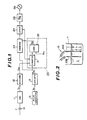
- Fig. 1 is a schematic block diagram showing one embodiment of an electronic liquid level gauge made in accordance with the present invention;
- Fig. 2 is a schematic view of an electrode pair used in the electronic liquid level gauge of Fig. 1;
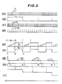
- Fig. 3 illustrates waveforms obtained at various points in the schematic block diagram of Fig. 1;
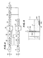
- Fig. 4 is a schematic block dfagram showing an alternative embodiment of the electronic liquid level gauge of the present invention;
- Fig. 5 is a schematic view of two electrode pairs used in the electronic liquid level gauge of Fig. 4; and
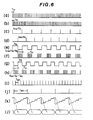
- Fig. 6 illustrates waveforms obtained at various points in the schematic block diagram of Fig. 4.
- Referring first to Figs. 1 and 2 of the drawings, there is illustrated one embodiment of an electronic liquid level gauge made in accordance with the present invention. The liquid level gauge employs an
electrode pair 10 which, as shown in Fig. 2, has two electrode plates 10A and 10B faced in spaced-parallel relation to each other and immersed in aliquid 2 contained in a vessel 1. The electrode plates constitute a capacitor having an electrostatic capacity determinative on the level of the liquid. Theelectrode pair 10 is associated with an oscillator 11 which generates oscillator pulses of a repetition period T11directly proportional to the electrostatic capacity of theelectrode pair 10. The oscillator pulse output is coupled to adivider 12 which has a predetermined frequency divisor N, so that the pulse signal outputted therefrom has a repetition period T,2 represented by T11x N1 - The liquid level gauge also employs a
reference pulse generator 13 which generates a series of reference pulses of a predetermined repetition period To. The reference pulses are coupled to adivider 14 which has a predetermined frequency divisor N2 so that the pulse signal outputted therefrom has a repetition period T14 represented by ToxN2. The output of thedivider 12 is coupled to amonostable multivibrator 20 which is shown as including acounter 21 and acomparator 22. When receiving a pulse from thedivider 12, thecounter 21 is reset to zero and at the same time starts counting pulses from thedivider 14. The output of thecounter 21 is coupled to thecomparator 22 which compares the value of the count in thecounter 21 with a reference value N3 and provides a high output when the former is equal to the latter. The output of thecomparator 22 is held low before the value of the count in thecounter 21 reaches the predetermined value N3. Thecounter 21 stops counting up in response to the high output of thecomparator 22. The output of thecomparator 22 is held low for a fixed time T22 during which thecounter 21 counts a predetermined number N3 of pulses having a repetition period T,4(=ToxN2). Consequently, the time T22 is represented by N3xN2xTo. - The output of the
monostable multivibrator 20 or thecomparator 22 is coupled to acounter 23 which starts counting pulses from thedivider 14 when the output of thecomparator 22 goes high. Thecounter 23 is reset to zero when the output of thecomparator 22 goes low which is caused by the next pulse applied from thedivider 12 to thecounter 21 so as to reset it to zero. The output of thecomparator 22 is also coupled to alatch circuit 24. Thelatch circuit 24 latches the value of the count in thecounter 23 just before thecounter 23 is reset when the output of thecomparator 22 goes low. The latched count value T23 is represented by T12―T22 The output of thelatch circuit 24 is coupled to a digital-to-analog converter 25 wherein the latched count value is converted into analog form. The output of the D to Aconverter 25 is coupled to ananalog meter 26 for indication of the converted analog value which represents the liquid level in a linear relationship to the electrostatic capacity C of theelectrode pair 10, as will be described in greater detail. - With particular reference now to Fig. 3, there are shown voltage-versus-time waveforms obtained at various points in the circuit of Fig. 1. Fig. 3a illustrates the pulse output produced by the oscillator 11. The oscillator pulse output has a repetition period T" directly proportional to the electrostatic capacity C of the
electrode pair 10. Fig. 3b illustrates the pulse output produced by thedivider 12. The divider pulse output has a repetition period T,2, represented by T11xN1 which is obtained as a result of dividing the repetition frequency 1/T11of the oscillator pulse output by a predetermined frequency divisor N,. Fig. 3c illustrates the pulse output produced by thereference pulse generator 13, which has a predetermined repetition period To. Fig. 3d illustrates the pulse output produced by thedivider 14. The divider pulse output has a repetition period T,4, represented by ToxN2, which is obtained as a result of dividing the repetition frequency 1/To of the generator output pulses by a predetermined frequency divisor N2. - At time t, when a pulse applied from the
divider 12 to thecounter 21, thecounter 21 starts counting the pulses from thedivider 14, as shown in Fig. 3e. At time t2 when the value of the count in thecounter 21 reaches a predetermined value N3, the output of thecomparator 22 changes from its low level to its high level, as shown in Fig. 3f, and at the same time thecounter 21 stops counting the pulses, as shown in Fig. 3e. The time T21 during which thecounter 21 counts a predetermined number N3 of pulses having a repetition period T,4(=ToxN2) from thedivider 14 is a fixed value represented by N3xN2xTo. - The counter 23 starts counting pulses from the
divider 14, as shown in Fig. 3g, at time t2 when the output of thecomparator 22 goes high. Thecounter 23 stops counting the pulses at time t3 when the output of thecomparator 22 goes low and thecounter 21 is reset to zero. At time t3, thecounter 21 starts counting pulses from thedivider 14 again, as shown in Fig. 3e. - As can be seen in Fig. 3, the time T23 during which the
counter 23 counts the pulses from thedivider 14 is represented by
counter 23 and latched in thelatch circuit 24 is given by
electrode pair 10 and can be represented by T'1 =Cx D, wherein D is a constant, equation (4) may be rewritten as
- It can be seen from a comparison of equations (2) and (10) that the value N latched in the
latch circuit 24 can be coincided with the liquid level I by suitably selecting the constant values N" N2, N3, D and To to satisfy the following equations (11) and (12):

- Upon the occurrence of a pulse from the
divider 12, the value N of the count in thecounter 23 is latched in thelatch circuit 24, as shown in Fig. 3h. The latched value is applied to the D to Aconverter 25 which converts it into analog form, as shown in Fig. 3i. The converted analog value is indicated on theanalog meter 26. - While the measured liquid level is indicated on an analog meter in this embodiment, it will be appreciated that a digital indicator may be used to provide thereon a digital indication of the measured liquid level by directly reading the count value in the
counter 23. The value in thecounter 23 or thelatch circuit 24 may be utilized for other calculations made based upon the measured liquid level, such as for example, calculations of the possible distance of travel of an automotive vehicle from values of fuel consumption rate and residual fuel quantity. - The
dividers divider 12. It is desirable in such applications to indicate the measured fuel level in the minute order to provide stabilized fuel level indication with the fuel level shaking being absorbed which occurs during automotive vehicle running. To achieve such stabilized fuel level indication, thedivider 12 may be designed to have a frequency divisor on the order of 108. Thedivider 14 may be eliminated in employing a reference pulse generator adapted to generate a series of pulses of a low repetition frequency. It is desirable, however, to use thedivider 14 because of cost and space considerations. Thereference pulse generator 13 normally includes a capacitor on which its time constant is determinative. A large and expensive capacitor is required to obtain a series of pulses having a low repetition frequency, resulting in a space-consuming and expensive structure. - It is preferable in automotive vehicle fuel level measuring applications to change the frequency divisor of the
divider 12 to a small value so that thedivider 12 generates pulses at elongated time intervals during vehicle travelling and to a large value so that thedivider 12 generates pulses at shortened time intervals during vehicle starting and refueling. This may be attained by replacing thedivider 12 with a presettable divider, the frequency divisor of which is changed in accordance with a signal such as, for example, a vehicle speed indicative signal from a vehicle speed sensor. - While the
monostable multivibrator 20 has been shown and described as comprised of acounter 21 and acomparator 22, there is no intention to be limited to such monostable multivibrator. Alternatively, a currently used monostable multivibrator having a CR time constant circuit may be used as long as its operation is maintained within closed tolerances. A further alternative device is a pulse generator which generates a first signal in response to a pulse from thedivider 12 and a second signal with a predetermined time delay relative to the occurrence of the pulse from thedivider 12. - Referring to Figs. 4 and 5, there is illustrated another embodiment of the electronic liquid level gauge of the present invention. The liquid level gauge employs first and second electrode pairs 30 and 40. The
first electrode pair 30 has twoelectrode plates 30A and 308 faced in spaced-parallel relation to each other and immersed in aliquid 2 contained in a vessel 1. Theelectrode plates second electrode pair 40 has twoelectrode plates liquid 2. Theelectrode plates second electrode pair 40 is placed near the bottom of the vessel 1. - The
first electrode pair 30 is associated with anoscillator 31 which generates oscillator pulses of a repetition period T3, directly proportional to the electrostatic capacity C, of thefirst electrode pair 30. The oscillator pulse output is coupled to adivider 32 which has a predetermined frequency divisor N32 so that the pulse signal outputted therefrom has a repetition period T32 represented by T32=T3, x N32. The divider pulse output is used to trigger amonostable multivibrator 33 into its unstable state. Themonostable multivibrator 33 generates a pulse signal having a pulse width T33 and a repetition period of T31 x N32. - The
second electrode pair 40 is associated with anoscillator 41 which generates oscillator pulses of a repetition period T4, directly proportional to the electrostatic capacity C2 of thesecond electrode pair 40. The oscillator pulse output is coupled to adivider 42 which has a predetermined frequency divisor N42 so that the pulse signal outputted therefrom has a repetition period T42 represented by T42=T41 x N42. - The output of the
monostable multivibrator 33 is coupled to agate circuit 34 which passes pulses from theoscillator 41 only when themonostable multivibrator 33 is in its stable state. Thus, the time during which thegate circuit 34 passes the oscillator pulses is represented by T41xN32-T33· The output of thegate circuit 34 is coupled through adivider 35 to acounter 36. Thedivider 35 has a predetermined frequency divisor N35. The output of themonostable multivibrator 43 is coupled to agate circuit 44 which passes pulses from theoscillator 31 only when themonostable multivibrator 43 is in its stable state. Thus, the time during which thegate circuit 44 passes the oscillator pulses is represented by T31xN42-T43· The output of thegate circuit 44 is coupled to adivider 45 having a predetermined frequency divisor N45. The output of thedivider 45 is coupled to thecounter 36 and also to alatch circuit 37. Thecounter 36 is reset to zero and at the same time starts counting pulses from thedivider 35 in response to a pulse from thedivider 45. Thelatch circuit 37 latches the value of the count in thecounter 36 in response to a pulse from thedivider 45. - With particular reference now to Fig. 6, there are shown voltage-versus-time waveforms obtained at various points in the circuit of Fig. 4. Figs. 6a to 6h are drawn on the same time scale. Figs. 6i to 61 are drawn on the same time scale but on the enlarged time scale as compared to that of Figs. 6a to 6h.
- Fig. 6a illustrates the pulse output produced by the
oscillator 31. The oscillator pulse output has a repetition period T3, directly proportional to the electrostatic capacity C, of thefirst electrode pair 30. The repetition period T3, is represented by B1xC1 wherein B1 is a constant. Fig. 6b illustrates the pulse output produced by theoscillator 41. The oscillator pulse output has a repetition period T4, directly proportional to the electrostatic capacity C2 of thesecond electrode pair 40. The repetition period T4, is represented by B2xC2, wherein B2 is a constant. Fig. 6C illustrates the pulse output produced by thedivider 32. The divider pulse output has a repetition period T3,xN32 obtained as a result of dividing the repetition frequency 1/T31 of the oscillator pulse output by a predetermined frequency divisor N33. Fig. 6d illustrates the pulse output produced by thedivider 42. The divider pulse output has a repetition period T41xN42 obtained as a result of dividing the repetition frequency 1/T41 of the oscillator pulse output by a predetermined frequency divisor N42. - Fig. 6e illustrates the pulse output produced by the
monostable multivibrator 33 which is triggered into its unstable state to provide a high output by a pulse from thedivider 32. The output of themonostable multivibrator 33 remains high for a predetermined time T33 and then goes low. Thus, the multivibrator pulse output has a pulse width of T33 and a repetition period equal to that of the pulse signal from thedivider 32. Fig. 6g illustrates the pulse output produced by themonostable multivibrator 43 which is triggered into its unstable state to provide a high output by a pulse from thedivider 42. The output of themonostable multivibrator 43 remains high for a predetermined time T43 and then goes low. Thus, the multivibrator pulse output has a pulse width of T43 and a repetition period equal to that of the pulse signal from thedivider 42. - Fig. 6f illustrates the pulse output produced by the
gate circuit 34 which responds to a stable state of themonostable multivibrator 33 for passing pulses from theoscillator 41. The time during which the monostable multivibrator is in its stable state is represented by N32 . T31-T33. Thus, the average repetition period TMO of the pulse signal from thegate circuit 34 may be given by
- Fig. 6h illustrates the pulse output produced by the
gate circuit 44 which responds to a stable state of themonostable multivibrator 43 for passing pulses from theoscillator 31. The time during which the monostable multivibrator is in its stable state is represented by N42xT41-T43. Thus, the average repetition period Tso of the pulse signal from thegate circuit 44 may be given by
- Fig. 6i illustrates the pulse output produced by the
divider 35 which divides the repetition frequency of the pulse signal from thegate circuit 34 by a predetermined dividing ratio N35. The divider output pulse has an average repetition rate TMO 1 which is represented by
- Fig. 6j illustrates the pulse output produced by the
divider 45 which divides the repetition frequency of the pulse signal from thegate circuit 44 by a predetermined frequency divisor N45. The divider output pulse has an average repetition rate Tso, which is represented by
- Fig. 6k illustrates the value of the count in the
counter 36 which is reset to zero and at the same time starts counting pulses from thedivider 35 when receiving a pulse from thedivider 45. Thelatch circuit 37 responds to a pulse from thedivider 45 for latching the value of the count in thecounter 36, as shown in Fig. 61. The latched value N is represented by
- It can be seen from a comparison of equations (7) and (17) that the value N latched in the
latch circuit 37 can be coincided with the liquid level I by suitably selecting the constants N32, N42, N35, N45, B1, 82, T33, and T43 to satisfy the following equations:

- The
divider 35, used for adjustment of the pulse sampling timing, may be eliminated in some instances dependent upon the kind of used liquid and the required accuracy of liquid level measurement. In automotive vehicle fuel level measuring applications, however, it is desirable to use the divider so as to provide stabilized fuel level measurement with the fuel level shaking being absorbed which occurs during automotive vehicle running. - While the present invention has been described in conjunction with specific embodiments thereof, it is evident that many alternatives, modifications and variations will be apparent to those skilled in the art.
Claims (13)
characterized in that
Applications Claiming Priority (4)
| Application Number | Priority Date | Filing Date | Title |
|---|---|---|---|
| JP56039186A JPS57153222A (en) | 1981-03-18 | 1981-03-18 | Liquid quantity measuring circuit |
| JP39186/81 | 1981-03-18 | ||
| JP96350/81 | 1981-06-22 | ||
| JP56096350A JPS57211018A (en) | 1981-06-22 | 1981-06-22 | Liquid quantity measuring circuit |
Publications (2)
| Publication Number | Publication Date |
|---|---|
| EP0061148A1 EP0061148A1 (en) | 1982-09-29 |
| EP0061148B1 true EP0061148B1 (en) | 1986-09-03 |
Family
ID=26378512
Family Applications (1)
| Application Number | Title | Priority Date | Filing Date |
|---|---|---|---|
| EP82102185A Expired EP0061148B1 (en) | 1981-03-18 | 1982-03-17 | Electronic liquid level gauge |
Country Status (3)
| Country | Link |
|---|---|
| US (1) | US4444051A (en) |
| EP (1) | EP0061148B1 (en) |
| DE (1) | DE3272970D1 (en) |
Families Citing this family (24)
| Publication number | Priority date | Publication date | Assignee | Title |
|---|---|---|---|---|
| US5049878A (en) * | 1981-05-13 | 1991-09-17 | Drexelbrook Engineering Company | Two-wire compensated level measuring instrument |
| US4611287A (en) * | 1982-08-16 | 1986-09-09 | Nissan Motor Company, Limited | Fuel volume measuring system for automotive vehicle |
| US4530372A (en) * | 1982-09-09 | 1985-07-23 | Conoco Inc. | Liquid level controller |
| US4733560A (en) * | 1983-10-24 | 1988-03-29 | Introtek International, Inc. | Liquid sensing system |
| US4589281A (en) * | 1984-09-20 | 1986-05-20 | Keystone International, Inc. | Material level detector and control |
| US4672840A (en) * | 1985-11-12 | 1987-06-16 | Mobil Oil Corporation | Method and system for determining fluid volumes of a two-phase effluent fluid flow through a porous material |
| US5042299A (en) * | 1990-07-23 | 1991-08-27 | Iimorrow, Inc. | Capacitive fluid level sensor |
| DE69835795T2 (en) | 1997-11-19 | 2007-09-13 | Grifols, S.A. | Device for the automatic performance of laboratory tests |
| ES2132034B1 (en) * | 1997-11-19 | 2000-03-01 | Grifols Grupo Sa | DEVICE FOR HANDLING AND DETECTION OF LIQUID LEVEL. |
| DE19800054A1 (en) * | 1998-01-02 | 1999-07-08 | Volkswagen Ag | Measuring device for a fuel gauge |
| JP3909618B2 (en) * | 1998-01-30 | 2007-04-25 | 本田技研工業株式会社 | Liquid fuel gauge for vehicles |
| US6295315B1 (en) * | 1999-04-20 | 2001-09-25 | Arnold M. Frisch | Jitter measurement system and method |
| EP1400787A1 (en) * | 2002-09-17 | 2004-03-24 | Nanmat Technology Co., Ltd. | Method for detecting quantity variation of high purity liquid chemicals and devices to carry out the method |
| DE10252562A1 (en) * | 2002-11-12 | 2004-05-27 | Volkswagen Ag | Car tank level measurement procedure, has capacitive sensor controlling extraction pump with dynamic related parameter threshold setting |
| EP1677084A1 (en) * | 2004-12-22 | 2006-07-05 | Roxer Industries S.A. | LIquid level sensor and method of estimation |
| US8602744B2 (en) * | 2005-03-25 | 2013-12-10 | Diversitech Corporation | Condensate pump |
| BRPI0504625A (en) * | 2005-07-05 | 2006-05-30 | Indebras Ind Eletromecanica Br | device for indicating the level of a liquid stored in a tank |
| FR2892509B1 (en) * | 2005-10-26 | 2007-12-21 | Inergy Automotive Systems Res | CAPACITIVE GAUGE FOR FUEL TANK |
| JP2009513963A (en) * | 2005-10-26 | 2009-04-02 | イナジー・オートモーティブ・システムズ・リサーチ・(ソシエテ・アノニム) | Capacitance type gauge |
| PL1862806T3 (en) * | 2006-06-01 | 2018-01-31 | Electrolux Home Products Corp Nv | Method and device for measuring the capacitance of a capacitive component |
| RU2329473C2 (en) * | 2006-06-15 | 2008-07-20 | Открытое акционерное общество "ТЕПЛОПРИБОР" | Instrument for level monitoring (level meter) |
| US8810260B1 (en) | 2007-04-02 | 2014-08-19 | Cypress Semiconductor Corporation | Device and method for detecting characteristics of a material occupying a volume with capactive sensing of mirrored plates |
| US8225654B2 (en) * | 2009-07-01 | 2012-07-24 | Tecan Trading Ag | Self-compensating capacitive liquid level detector |
| DE102010010749B4 (en) * | 2010-03-09 | 2016-12-22 | Wacker Neuson Produktion GmbH & Co. KG | Drive system with a device for interrupting the operation in the case of impending lack of fuel as well as implement and method |
Family Cites Families (7)
| Publication number | Priority date | Publication date | Assignee | Title |
|---|---|---|---|---|
| US4083248A (en) * | 1975-09-04 | 1978-04-11 | Simmonds Precision Products, Inc. | Digital liquid-level gauging systems |
| GB1601338A (en) * | 1977-03-14 | 1981-10-28 | Huddart R | Measuring apparatus using parameter dependant capacitance |
| US4226118A (en) * | 1978-07-28 | 1980-10-07 | Keystone International, Inc. | Level detector |
| US4235106A (en) * | 1978-12-08 | 1980-11-25 | Drexelbrook Controls, Inc. | System and method for obtaining compensated level measurements |
| DE2852212A1 (en) * | 1978-12-02 | 1980-06-19 | Vdo Schindling | capacitor level sensor with dielectric constant compensation - has air and fluid filled compensation and measurement capacitors |
| US4214479A (en) * | 1979-05-21 | 1980-07-29 | Simmonds Precision Products, Inc. | Capacitive type fuel probe compensation circuit |
| JPS5619723U (en) * | 1979-07-23 | 1981-02-21 |
-
1982
- 1982-03-12 US US06/357,585 patent/US4444051A/en not_active Expired - Lifetime
- 1982-03-17 DE DE8282102185T patent/DE3272970D1/en not_active Expired
- 1982-03-17 EP EP82102185A patent/EP0061148B1/en not_active Expired
Also Published As
| Publication number | Publication date |
|---|---|
| US4444051A (en) | 1984-04-24 |
| EP0061148A1 (en) | 1982-09-29 |
| DE3272970D1 (en) | 1986-10-09 |
Similar Documents
| Publication | Publication Date | Title |
|---|---|---|
| EP0061148B1 (en) | Electronic liquid level gauge | |
| US4470296A (en) | Fuel gauge for an automotive vehicle | |
| US3534606A (en) | Fuel gage | |
| US4201085A (en) | Apparatus for determining the liquid level in a tank | |
| US4296472A (en) | Non-intrusive fluid measuring system | |
| US3699320A (en) | Temperature compensated liquid metering system and method | |
| US4399699A (en) | Electrostatic type fuel measuring device | |
| JPS6236161B2 (en) | ||
| GB2097129A (en) | Capacitance liquid level and concentration apparatus | |
| US3115615A (en) | Measuring systems | |
| US3312107A (en) | Liquid storage and measuring system | |
| US3985022A (en) | Ultrasonic thickness measuring method and apparatus | |
| DE2948961C2 (en) | Measuring device for the mass flow of the intake air of an internal combustion engine with a Karman vortex sensor | |
| US4012948A (en) | Fuel consumption measuring device | |
| US4214479A (en) | Capacitive type fuel probe compensation circuit | |
| US3008332A (en) | Supersonic pressure gauge | |
| US4531407A (en) | Fuel gauge for an automotive vehicle | |
| US3612876A (en) | Standardization system for a digital radiation gauge | |
| RU2163005C2 (en) | Technique measuring quantity of fuel in tank of motor vehicle | |
| US4448071A (en) | Method of measuring and indicating fluid levels | |
| US3619613A (en) | Digital measuring system utilized in standardizing a nucleonic measuring gauge | |
| JPS6310771B2 (en) | ||
| US3697730A (en) | Apparatus to produce data count signals | |
| JPH0113523B2 (en) | ||
| USRE27246E (en) | Electroniciliquid measuring system |
Legal Events
| Date | Code | Title | Description |
|---|---|---|---|
| PUAI | Public reference made under article 153(3) epc to a published international application that has entered the european phase |
Free format text: ORIGINAL CODE: 0009012 |
|
| AK | Designated contracting states |
Designated state(s): DE FR GB |
|
| 17P | Request for examination filed |
Effective date: 19820825 |
|
| RAP1 | Party data changed (applicant data changed or rights of an application transferred) |
Owner name: NISSAN MOTOR CO., LTD. |
|
| GRAA | (expected) grant |
Free format text: ORIGINAL CODE: 0009210 |
|
| AK | Designated contracting states |
Kind code of ref document: B1 Designated state(s): DE FR GB |
|
| REF | Corresponds to: |
Ref document number: 3272970 Country of ref document: DE Date of ref document: 19861009 |
|
| ET | Fr: translation filed | ||
| PLBE | No opposition filed within time limit |
Free format text: ORIGINAL CODE: 0009261 |
|
| STAA | Information on the status of an ep patent application or granted ep patent |
Free format text: STATUS: NO OPPOSITION FILED WITHIN TIME LIMIT |
|
| 26N | No opposition filed | ||
| PGFP | Annual fee paid to national office [announced via postgrant information from national office to epo] |
Ref country code: FR Payment date: 19910131 Year of fee payment: 10 |
|
| PG25 | Lapsed in a contracting state [announced via postgrant information from national office to epo] |
Ref country code: FR Effective date: 19921130 |
|
| REG | Reference to a national code |
Ref country code: FR Ref legal event code: ST |
|
| PGFP | Annual fee paid to national office [announced via postgrant information from national office to epo] |
Ref country code: GB Payment date: 19970310 Year of fee payment: 16 |
|
| PGFP | Annual fee paid to national office [announced via postgrant information from national office to epo] |
Ref country code: DE Payment date: 19970321 Year of fee payment: 16 |
|
| PG25 | Lapsed in a contracting state [announced via postgrant information from national office to epo] |
Ref country code: GB Free format text: LAPSE BECAUSE OF NON-PAYMENT OF DUE FEES Effective date: 19980317 |
|
| GBPC | Gb: european patent ceased through non-payment of renewal fee |
Effective date: 19980317 |
|
| PG25 | Lapsed in a contracting state [announced via postgrant information from national office to epo] |
Ref country code: DE Free format text: LAPSE BECAUSE OF NON-PAYMENT OF DUE FEES Effective date: 19981201 |