EP0060866B1 - Seat belt retractor assembly with pawl mounted pendulum - Google Patents
Seat belt retractor assembly with pawl mounted pendulum Download PDFInfo
- Publication number
- EP0060866B1 EP0060866B1 EP81902698A EP81902698A EP0060866B1 EP 0060866 B1 EP0060866 B1 EP 0060866B1 EP 81902698 A EP81902698 A EP 81902698A EP 81902698 A EP81902698 A EP 81902698A EP 0060866 B1 EP0060866 B1 EP 0060866B1
- Authority
- EP
- European Patent Office
- Prior art keywords
- pawl
- locking pawl
- locking
- actuation
- spool
- Prior art date
- Legal status (The legal status is an assumption and is not a legal conclusion. Google has not performed a legal analysis and makes no representation as to the accuracy of the status listed.)
- Expired
Links
Images


Classifications
-
- B—PERFORMING OPERATIONS; TRANSPORTING
- B60—VEHICLES IN GENERAL
- B60R—VEHICLES, VEHICLE FITTINGS, OR VEHICLE PARTS, NOT OTHERWISE PROVIDED FOR
- B60R22/00—Safety belts or body harnesses in vehicles
- B60R22/34—Belt retractors, e.g. reels
- B60R22/36—Belt retractors, e.g. reels self-locking in an emergency
- B60R22/40—Belt retractors, e.g. reels self-locking in an emergency responsive only to vehicle movement
-
- B—PERFORMING OPERATIONS; TRANSPORTING
- B60—VEHICLES IN GENERAL
- B60R—VEHICLES, VEHICLE FITTINGS, OR VEHICLE PARTS, NOT OTHERWISE PROVIDED FOR
- B60R22/00—Safety belts or body harnesses in vehicles
- B60R22/34—Belt retractors, e.g. reels
- B60R2022/3424—Multi-spool or multi-belt retractors
-
- B—PERFORMING OPERATIONS; TRANSPORTING
- B60—VEHICLES IN GENERAL
- B60R—VEHICLES, VEHICLE FITTINGS, OR VEHICLE PARTS, NOT OTHERWISE PROVIDED FOR
- B60R22/00—Safety belts or body harnesses in vehicles
- B60R22/34—Belt retractors, e.g. reels
- B60R22/3416—Unlocking devices for retractors
Definitions
- the present invention relates to an emergency seat belt mechanism that has automatic inertia locking during an emergency condition, wherein an inertia mass which accomplishes the locking mounts upon the locking pawl, and a secondary or actuation pawl is used to moved the main locking pawl.
- US-A-4162773 discloses a mechanism of the type set forth in the preamble of Claim 1, in which the actuation pawl is a lever pivotally mounted on the locking pawl, and the actuation pawl acts on the main ratchet which is locked by the locking pawl, rather than on a secondary pawl.
- Both US-A-3 834 646 and US-A-3 923 269 disclose retractor mechanisms in which a secondary ratchet wheel is engaged by the actuation pawl, which then rotates the locking pawl into engagement with the main ratchet wheel on the belt spool.
- the inertia responsive weight is suspended from the frame rather than from the locking spool, and this makes angular adjustment extremely difficult, and can result in excessive pawl vibration with consequent noise.
- an object of the present invention to provide an inertia locking system, which prevents the undesired vibrations of a locking pawl, in which the inertia mass is always properly oriented with respect to its housing and the vehicle, and in which the problem of the locking pawl hitting the tip of a ratchet tooth on a spool and bouncing back from a desired locking position is overcome. Further, it is desired to overcome the problems associated with the mounting of the actuation pawl on a pivot pin on the locking pawl.
- the retractor of the present invention may utilize a locking pawl which may be manually released in a post emergency condition. See copending European Patent Application No. 81902571 (publication No. WO 82/01136).
- the locking pawl is generally urged into a locked position by the motion of an inertia mass.
- the inertia mass is mounted upon the housing of the assembly.
- the present invention relates to the type which mounts the mass upon the locking pawl.
- an emergency locking seat belt retractor including a belt winding spool, a first ratchet wheel operatively connected to the spool, a second ratchet wheel operatively connected to the spool, a locking pawl movable between a rest position and an actuated position wherein the locking pawl engages the first ratchet wheel to lock the spool, an actuating pawl mounted on the locking pawl for movement between a rest position and an actuated position wherein the actuating pawl engages the second ratchet wheel such that unwinding of the spool causes the actuation pawl to move the locking pawl into the actuated position thereof, and an inertia responsive mass mounted on the locking pawl and arranged to cause the actuation pawl to move to the actuated position thereof in response to a change in inertia caused by an emergency, characterised in that the locking pawl has one end thereof provided with at least one slot
- the inertia mass is rotated by that sudden stop to lift the second pawl into engagement with a second set of ratchet teeth mounted upon the surface of a spool holding the seat belt.
- the second pawl and ratchet are provided with sharp teeth which, once engaged, draw the second pawl into further engagement with the second ratchet teeth.
- the second pawl, mounted upon the first locking pawl in turn, pulls the first locking pawl into engagement with a first set of teeth on the outer edges of the-spool which mounts the safety belt.
- the weight of the inertia mass retains the locking pawl against vibration thus reducing noise within the vehicle.
- By mounting the inertia mass upon the locking pawl it is also possible to use an insert in the pawl which permits the inertia mass to remain vertical at any mounting angle.
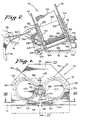
- FIG 1 shows a seat belt retractor mechanism 10 including a housing 12 formed from a stamped metal sheet mounted upon a vehicle frame 14, Figure 2. It will be seen in Figure 2 that the housing 12 is formed with its base parallel to the frame of the vehicle and its oppositely extending arms 16 bent at an angle to the frame 14. Mounted between the arms 16 is a spool shaft 18 which rotatably mounts a spool 20 formed with spool ends 22 having ratchet-like teeth 24 on the periphery of each spool end.
- a seat belt 26 which may be protracted from the spool 20 by the user in an active seat belt system or by the opening of the vehicle door in a passive seat belt system.
- the base of the housing 12 is arranged at an angle to the arms 16 to permit the shaft 18 and spool 20 to be arranged at a suitable angle. This permits the seat belt 26 to be protracted from its spool 20 and about the user at a comfortable angle.
- the seat belt retractor mechanism 10 is shown with two seat belt retractor spools because most automobiles have side- by-side seating arrangements. The present seat belt retractor mechanism may be utilized with but a single spool 20 and belt 26.
- an automatic inertia locking system formed by a locking pawl 28 mounted between the housing arms 16 within suitable apertures 30, Figure 1, and 32, Figure 5.
- the locking pawl is formed from a planar sheet of metal with its longitudinal axis substantially longer than its lateral axis.
- the pawl 28 passes through apertures 30 and 32 and is retained therein by extending tabs 34 which are wider than the opening 30 and may be urged against that opening by spring loaded lever means to be described hereinbelow.
- the tabs 34 extend laterally from the longitudinal axis of the locking pawl 28 and rest in their normal position on the horizontal, lower edges of apertures 30 and 32. This position is retained, to some extent, by an inertia mass 36 which is mounted upon one end of the locking pawl 28.
- the inertia mass 36 seen in Figure 2, comprises the mass 36 attached by a stem 38 to an actuator 40.
- the stem passes through an aperture within a tab 42, Figure 3, which is separated from the remainder of the locking pawl 28 by a longitudinal slit 44 and bent at an angle thereto so that the mass 36 hangs vertically toward the frame 14.
- a sudden deceleration of the vehicle in which the seat belt retractor mechanism 10 is mounted will cause the mass 36 to rotate to the left, Figure 2, causing the actuator 40 to rotate about its edge.
- the locking pawl 28 is rotated into engagement with the ratchet teeth 24 to lock the spool 20 and prevent further protraction of the seat belt 26.
- the present invention utilizes a second pawl and ratchet combination.
- a second ratchet 46 is formed from a plastic piece mounted upon shaft 18 on the external side of the housing arm 16, as shown in Figs. 2 and 4.
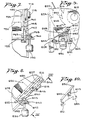
- Each ratchet tooth 48 formed on the second ratchet 46 has a sharper tooth angle which engages a similar tooth 50 on a second pawl 52, Fig. 6.
- the second pawl 52 which in this embodiment may be a molded plastic piece, is formed with two apertures 54 and 56 for clearing the end of the locking pawl 28.
- the narrow sections of the second pawl 52 pass through the slots 44 in the end of the locking pawl 28 wherein the angular bend applied to the end of the locking pawl secures the second locking pawl 52 into position.
- Extending at an acute angle from the center of the second locking pawl 52 is an actuator engaging tab 58 which contacts the top of actuator 40 attached to the mass 36, Fig. 2.
- a similar tab 60 extends at a right angle from the lower end of locking pawl 52 to engage the surface of locking pawl 28 as the second pawl is raised by the action of ratchet teeth 48 on the second ratchet 46.
- the second ratchet 46 and locking pawl 52 form a programmed pawl retractor with ratchet 22 and pawl 28.
- the second ratchet and locking pawl solves a pawl bounce problem similar to the problem solved by the dual lock bar shown in Patent 3,899,898.
- the mass 36 moves to the left, Fig. 2, to rotate the actuator 40 and raise the locking pawl 52 through contact with the tab 58.
- tooth 50 engages a ratchet tooth 48 and is drawn upward, pulling the first locking pawl 28 with it into engagement with a ratchet tooth 24.
- ratchet teeth 48 With ratchet teeth 22 assures the continued movement of the pawl 28 into engagement with teeth 22 without bouncing back from such engagement. This movement locks the seat belt retractor mechanism 10 to prevent the further protraction of the belt 26.
- the sharpness of the plastic ratchet teeth 48 is such that they will not cause a bounce back when engaged by the pawl tooth 50.
- the teeth of the two molded plastic parts, 46 and 50 may be made much sharper than the corresponding teeth of the metal part, 24 and 28, which must carry the mechanical stress created by impact.
- the mass 36 may not return to its vertical position thus raising the possibility of locking the seat belt retractor mechanism 10 to prevent further protraction of the seat belt 26.
- the user may be placing tension upon the seat belt 26 in a post emergency condition to retain the locking pawl 28 against the ratchet tooth 24.
- the locking pawl 28 may be moved along its longitudinal axis for changing the alignment of teeth 34 shown in Fig. 3 and described in greater detail in WO-A-82/01136. In the realigned condition the tabs 34 no longer engage the ratchet teeth 24 thus permitting the spool 20 which stores seat belt 26 to turn freely.
- Figs. 1 and 2 there are several arrangements which may be used to move the locking pawl 28 manually transversely along its longitudinal axis.
- the embodiment shown in Figs. 1 and 2 includes a lever 62 formed from two stamped sheet metal parts whose lower sections have been displaced, Fig. 1, and provided with apertures 64, Fig. 2, which fit about tabs 66 that extend inwardly from the locking pawls 28, Fig. 3.
- the lever 62 is attached to the housing 12 by a shaft 68 which passes through a tab 70 that may be formed by stamping and bending metal from the surface of the housing arm 16.
- the shaft 68 is retained within tab 70 by staking; while an extended shoulder 72 retains the levers 62 in the position shown.
- a spring 74 urges the levers 62 into a first position wherein the engagement of aperture 64 about locking pawl tab 66 forces the tab 34 against housing 12 to retain the locking pawl 28 therein.
- a two- position release handle 76 is attached to a shaft 78 mounted upon the vehicle frame 14 as shown in Fig. 2. Connecting the handle 76 to the lever 62 is a connecting rod 80 which may also be formed from a flexible cable. The handle 76 may be raised against the urging of the spring 74 until the rod 80 passes beyond the center of shaft 78. At this time, the spring 74 tends to lock the handle 76 into the second position shown in phantom in Fig. 2.
- FIG. 7 A second embodiment of the present invention is shown at Fig. 7, which is similar to Fig. 2 except that the arms 716 of the retractor assembly are arranged at right angles to the frame, not shown.
- a shaft 178 is mounted within an aperture in arm 716 to support a spool 720 having disk shaped spool ends 722 with ratchet teeth 724 on the outer periphery thereof.
- Mounted between the arms 716 is a locking pawl 728 upon which an inertia mass 736 is mounted by an actuator 740.
- a second locking pawl 752 also mounts upon the end of the locking pawl 728 in a similar manner to the mounting of the second pawl 52 upon the locking pawl 28.
- the tab 758 extends at a right angle from the second pawl 752 and engages, via a detent 759, the upper actuator portion 740 of the inertia mass 736 hanging vertically from the pawl 728. As the inertia mass rotates, it lifts the second pawl 752 which engages ratchet teeth 748 upon a second ratchet 746.
- the locking pawl 728 is arranged to mount the inertia mass 736 upon a surface parallel to the mounting surface of the frame.
- the tab 758 is arranged at a right angle or substantially parallel to the mounting surface. This assures a maximum amount of displacement of pawl 752 caused by the rotational motion of the mass 736 which displaces the actuator 740.
- FIG. 8 and 9 A third embodiment of the present invention is shown in Figs. 8 and 9 wherein arms 816 which support a shaft 818 about which is rotatably mounted a spool 820 having ratchet teeth 824 upon spool ends 822. Mounted between the arms 816 is a locking pawl 828 whose lowermost end is bent at an angle to form a tab 842 which is parallel to the frame of the vehicle, not shown, and perpendicular to the vertical axis of the vehicle under normal operating conditions. Mounted upon the tab 842 is an inertia mass 836 which is connected by a stem 838 to an actuator 840.
- a second pawl 852, Fig. 10, is mounted within notched slots 845, as shown in Fig. 9.
- the notched slots placed in pawl 828 retain the second pawl 852 in the position shown upon the locking pawl 828.
- Locking pawl 852 is formed with a generally flat cross-section having a detent 849 extending at an acute angle away from the flat surface thereof.
- the opposite end of the pawl 852 is provided with two extending L-shaped tabs 851 and 853 which retain the pawl 852 within slots 845.
- On the upper most end of the pawl 852 is a tooth 850 which engages a second ratchet 846 having ratchet teeth 848 mounted on shaft 818 and spool end 822.
- Figs. 11-13 a last embodiment of a preferred invention will be shown. It will be noted from Figs. 2, 7 and 8 that the inertia mass 36 should hang in a vertical direction toward the frame of the vehicle. Tab 42 must be bent on a locking pawl 28 at various angles.
- the embodiments of Figs. 8 and 9 demonstrate one configuration which may be used when the angle between the vehicle and the locking pawl 828 is substantial. However, to eliminate the need for various pieces having various angles, a molded plastic piece may be used along with the molded second ratchet and second locking pawl.
- the frame 1116 supports a shaft 1118 upon which is mounted the spool 1120 having ends 1122 with ratchet teeth 1124 on the outer periphery of each end.
- a locking pawl 1128 mounts between the arms 1116 as in the prior embodiment.
- the locking pawl is provided with a molded piece 1182 which is mounted within an irregular slot 1184 on the end of the locking pawl adjacent a second ratchet 1146.
- the slot 1184 is generally rectangular with edges that receive C-shaped end tabs 1186, Fig. 13, on each side of the molded piece 1182 wherein the C-shaped tabs grip the thickness of the locking pawl 1128.
- An extending arm 1188 is provided with a shouldered detent 1190 that engages an aperture 1192 located in the locking pawl 1128 for latching the molded piece 1182 thereto.
- Webs 1194 connected the C-shaped tabs 1186 to a central platform 1196 of the molded piece 1182 where an inertia mass 1136 is mounted.
- Molded insert 1182 may be arranged with any angle between its C-shaped tabs 1186 and its mounting platform 1196. Similarly, a second pawl 1152 is arranged with a tab 1158 extending at an angle therefrom. It will now be seen that the angle of the platform 1196 and the tab 1158 may be adjusted by simply changing the molded parts which are used. In this manner, the seat belt retractor mechanism 10 may be designed for mounting in one of several orientations. All that one need do to accommodate the several orientations is simply replace the molded plastic pieces 1152 and 1182.
- a sudden stop of the vehicle in which the seat belt retractor mechanism is mounted will cause the inertia mass 1136 to rotate thus rotating the actuator 1140 and lifting the second pawl 1152.
- the tooth 1150 engages one of the ratchet teeth 1148 upon ratchet 1146.
- the sharp angle of the second ratchet teeth draws the second pawl 1152 in an upward direction and pulls the first metal latching pawl 1128 into a latching configuration with the ratchet teeth 1124 ' upon the spool ends 1122.
- the molded plastic parts which form the second pawl 1152 and the second ratchet 1146 for example, it is possible to shape the ratchet teeth 1148 or the pawl tooth 1150 at a sharp angle thus permitting easy engagement without the probability of a bounce back condition should the tip of one to the teeth contact the tip of another.
- These sharp teeth may be used in the embodiments shown as the design does not require the second engaging pawl or second ratchet teeth to carry the force exerted upon the seat belt retractor mechanism by the pressure of a user in a sudden deceleration.
- the molded pieces simply act as the mechanism device for moving the metal latching pawl 1128 into engagement with the ratchet teeth 1124.
- the molded insert 1182 By using the molded insert 1182, it is possible to utilize the same seat belt retractor mechanism in several orientations by simply changing the molded parts 1152 and 1182. Further, the molded insert 1182 provides a softer surface upon which the inertia mass 1136 may rest, thus further reducing any high frequency vibration noise caused by the loosely hanging inertia mass 1136.
Landscapes
- Engineering & Computer Science (AREA)
- Mechanical Engineering (AREA)
- Automotive Seat Belt Assembly (AREA)
Priority Applications (1)
| Application Number | Priority Date | Filing Date | Title |
|---|---|---|---|
| AT81902698T ATE14698T1 (de) | 1980-10-06 | 1981-09-17 | Sitzgurtrueckzugeinrichtung mit an einer klinke gelagertem pendel. |
Applications Claiming Priority (2)
| Application Number | Priority Date | Filing Date | Title |
|---|---|---|---|
| US06/193,958 US4371128A (en) | 1980-10-06 | 1980-10-06 | Seat belt retractor assembly with pawl mounted pendulum |
| US193958 | 1994-02-09 |
Publications (3)
| Publication Number | Publication Date |
|---|---|
| EP0060866A1 EP0060866A1 (en) | 1982-09-29 |
| EP0060866A4 EP0060866A4 (en) | 1983-02-04 |
| EP0060866B1 true EP0060866B1 (en) | 1985-08-07 |
Family
ID=22715735
Family Applications (1)
| Application Number | Title | Priority Date | Filing Date |
|---|---|---|---|
| EP81902698A Expired EP0060866B1 (en) | 1980-10-06 | 1981-09-17 | Seat belt retractor assembly with pawl mounted pendulum |
Country Status (9)
| Country | Link |
|---|---|
| US (1) | US4371128A (ja) |
| EP (1) | EP0060866B1 (ja) |
| JP (1) | JPS57501516A (ja) |
| AU (1) | AU544502B2 (ja) |
| BR (1) | BR8105173A (ja) |
| CA (1) | CA1169407A (ja) |
| ES (1) | ES268711Y (ja) |
| IT (1) | IT1142879B (ja) |
| WO (1) | WO1982001137A1 (ja) |
Families Citing this family (2)
| Publication number | Priority date | Publication date | Assignee | Title |
|---|---|---|---|---|
| US4492349A (en) * | 1981-09-08 | 1985-01-08 | American Safety Equipment Corporation | Programmed pawl control means |
| JPH0256059U (ja) * | 1988-10-17 | 1990-04-23 |
Family Cites Families (5)
| Publication number | Priority date | Publication date | Assignee | Title |
|---|---|---|---|---|
| US3923269A (en) * | 1970-11-06 | 1975-12-02 | Kangol Magnet Ltd | Inertia reels for vehicle safety belts |
| CA1004203A (en) * | 1971-11-09 | 1977-01-25 | Robert B. Heath | Take-up spool latch |
| US3946965A (en) * | 1974-12-23 | 1976-03-30 | Ford Motor Company | Vehicle sensitive inertia retractor |
| US4046332A (en) * | 1975-05-02 | 1977-09-06 | Allied Chemical Corporation | Support for safety belt retractor inertia mechanism |
| SE405209B (sv) * | 1977-04-22 | 1978-11-27 | Irvin Industries Inc | Anordning vid automatlas for bandformiga sekerhetsbelten |
-
1980
- 1980-10-06 US US06/193,958 patent/US4371128A/en not_active Expired - Lifetime
-
1981
- 1981-08-12 BR BR8105173A patent/BR8105173A/pt unknown
- 1981-09-17 EP EP81902698A patent/EP0060866B1/en not_active Expired
- 1981-09-17 AU AU76428/81A patent/AU544502B2/en not_active Ceased
- 1981-09-17 JP JP56503174A patent/JPS57501516A/ja active Pending
- 1981-09-17 WO PCT/US1981/001249 patent/WO1982001137A1/en active IP Right Grant
- 1981-09-21 ES ES1981268711U patent/ES268711Y/es not_active Expired
- 1981-10-05 CA CA000387311A patent/CA1169407A/en not_active Expired
- 1981-10-05 IT IT49430/81A patent/IT1142879B/it active
Also Published As
| Publication number | Publication date |
|---|---|
| WO1982001137A1 (en) | 1982-04-15 |
| AU544502B2 (en) | 1985-05-30 |
| US4371128A (en) | 1983-02-01 |
| CA1169407A (en) | 1984-06-19 |
| IT8149430A0 (it) | 1981-10-05 |
| AU7642881A (en) | 1982-05-11 |
| EP0060866A1 (en) | 1982-09-29 |
| EP0060866A4 (en) | 1983-02-04 |
| JPS57501516A (ja) | 1982-08-26 |
| ES268711Y (es) | 1984-01-16 |
| BR8105173A (pt) | 1982-08-31 |
| IT1142879B (it) | 1986-10-15 |
| ES268711U (es) | 1983-07-01 |
Similar Documents
| Publication | Publication Date | Title |
|---|---|---|
| EP0061465B1 (en) | Seat belt retractor assembly with post emergency spool release | |
| EP0073091A2 (en) | Automatic locking safety belt retraction apparatus with resetting means | |
| US4277037A (en) | Lock bar release for inertia locking seat belt retractor | |
| EP0786384B1 (en) | Seat belt retractor | |
| EP1079996A1 (en) | Retractor for vehicles | |
| EP0060866B1 (en) | Seat belt retractor assembly with pawl mounted pendulum | |
| US4085905A (en) | Blocking device preferably for reel-type safety belts for vehicles | |
| US4059242A (en) | Safety belt retractor | |
| US5137226A (en) | Seat belt retractor with reinforced seat belt guide | |
| US4253621A (en) | Vehicle-sensitive blocking device | |
| US4760975A (en) | Seat belt retractor | |
| CA1187460A (en) | Programmed pawl control means | |
| JPS60174110A (ja) | 座席の背もたれの傾斜を調節する機構 | |
| CA1169835A (en) | Resiliently mounted split pawl locking means for dual spool retractor | |
| US5507449A (en) | Seat belt retractor with noise suppression | |
| CA1153349A (en) | Dual reel retractor | |
| US4027829A (en) | Flywheel and clutch mechanism for safety belt retractor | |
| US4765559A (en) | Synchronized safety belt retractor with structural control locking means | |
| EP1160121B1 (en) | Device for securing a seat back to a body of a motor vehicle | |
| JPH0929U (ja) | 車両安全ベルト系用ベルト引込装置 | |
| US4396167A (en) | Lock bar and belt clamp release for seat belt retractor | |
| US4984752A (en) | Safety belt retractor and method of manufacture | |
| US4705230A (en) | Horizontal retractor | |
| JP2530423Y2 (ja) | 安全ベルトのバックル緊急引込装置 | |
| US3940082A (en) | Blocking member for locking mechanism of a vehicle occupant restraint belt retractor |
Legal Events
| Date | Code | Title | Description |
|---|---|---|---|
| PUAI | Public reference made under article 153(3) epc to a published international application that has entered the european phase |
Free format text: ORIGINAL CODE: 0009012 |
|
| 17P | Request for examination filed |
Effective date: 19820519 |
|
| AK | Designated contracting states |
Designated state(s): AT CH DE FR GB LU NL SE |
|
| GRAA | (expected) grant |
Free format text: ORIGINAL CODE: 0009210 |
|
| AK | Designated contracting states |
Designated state(s): AT CH DE FR GB LI LU NL SE |
|
| PG25 | Lapsed in a contracting state [announced via postgrant information from national office to epo] |
Ref country code: NL Effective date: 19850807 Ref country code: LI Effective date: 19850807 Ref country code: CH Effective date: 19850807 Ref country code: AT Effective date: 19850807 |
|
| REF | Corresponds to: |
Ref document number: 14698 Country of ref document: AT Date of ref document: 19850815 Kind code of ref document: T |
|
| REF | Corresponds to: |
Ref document number: 3171710 Country of ref document: DE Date of ref document: 19850912 |
|
| PG25 | Lapsed in a contracting state [announced via postgrant information from national office to epo] |
Ref country code: LU Free format text: LAPSE BECAUSE OF NON-PAYMENT OF DUE FEES Effective date: 19850930 |
|
| ET | Fr: translation filed | ||
| REG | Reference to a national code |
Ref country code: CH Ref legal event code: PL |
|
| NLV1 | Nl: lapsed or annulled due to failure to fulfill the requirements of art. 29p and 29m of the patents act | ||
| PLBE | No opposition filed within time limit |
Free format text: ORIGINAL CODE: 0009261 |
|
| STAA | Information on the status of an ep patent application or granted ep patent |
Free format text: STATUS: NO OPPOSITION FILED WITHIN TIME LIMIT |
|
| 26N | No opposition filed | ||
| PG25 | Lapsed in a contracting state [announced via postgrant information from national office to epo] |
Ref country code: GB Effective date: 19890917 |
|
| PG25 | Lapsed in a contracting state [announced via postgrant information from national office to epo] |
Ref country code: SE Effective date: 19890918 |
|
| GBPC | Gb: european patent ceased through non-payment of renewal fee | ||
| PG25 | Lapsed in a contracting state [announced via postgrant information from national office to epo] |
Ref country code: FR Effective date: 19900531 |
|
| PG25 | Lapsed in a contracting state [announced via postgrant information from national office to epo] |
Ref country code: DE Effective date: 19900601 |
|
| REG | Reference to a national code |
Ref country code: FR Ref legal event code: ST |
|
| EUG | Se: european patent has lapsed |
Ref document number: 81902698.0 Effective date: 19900521 |