EP0060763B2 - Dispositif de roulement et de guidage d'une tuyère orientable de propulseur à réaction - Google Patents
Dispositif de roulement et de guidage d'une tuyère orientable de propulseur à réaction Download PDFInfo
- Publication number
- EP0060763B2 EP0060763B2 EP82400393A EP82400393A EP0060763B2 EP 0060763 B2 EP0060763 B2 EP 0060763B2 EP 82400393 A EP82400393 A EP 82400393A EP 82400393 A EP82400393 A EP 82400393A EP 0060763 B2 EP0060763 B2 EP 0060763B2
- Authority
- EP
- European Patent Office
- Prior art keywords
- fixed
- movable
- spherical seating
- outer spherical
- seating
- Prior art date
- Legal status (The legal status is an assumption and is not a legal conclusion. Google has not performed a legal analysis and makes no representation as to the accuracy of the status listed.)
- Expired
Links
- 238000007789 sealing Methods 0.000 claims description 12
- 238000005096 rolling process Methods 0.000 claims description 11
- 239000000463 material Substances 0.000 claims description 5
- 230000005540 biological transmission Effects 0.000 claims 1
- 230000001413 cellular effect Effects 0.000 claims 1
- 238000011068 loading method Methods 0.000 claims 1
- 239000002184 metal Substances 0.000 claims 1
- 239000007769 metal material Substances 0.000 claims 1
- 239000012528 membrane Substances 0.000 description 4
- 230000004048 modification Effects 0.000 description 4
- 238000012986 modification Methods 0.000 description 4
- 238000011144 upstream manufacturing Methods 0.000 description 4
- 239000000112 cooling gas Substances 0.000 description 3
- 239000007789 gas Substances 0.000 description 3
- 239000006096 absorbing agent Substances 0.000 description 2
- 230000000712 assembly Effects 0.000 description 2
- 238000000429 assembly Methods 0.000 description 2
- 238000004519 manufacturing process Methods 0.000 description 2
- 230000035939 shock Effects 0.000 description 2
- 238000003466 welding Methods 0.000 description 2
- OKTJSMMVPCPJKN-UHFFFAOYSA-N Carbon Chemical compound [C] OKTJSMMVPCPJKN-UHFFFAOYSA-N 0.000 description 1
- 206010034719 Personality change Diseases 0.000 description 1
- 241000209140 Triticum Species 0.000 description 1
- 235000021307 Triticum Nutrition 0.000 description 1
- 229910052799 carbon Inorganic materials 0.000 description 1
- 238000006243 chemical reaction Methods 0.000 description 1
- 238000002485 combustion reaction Methods 0.000 description 1
- 239000002131 composite material Substances 0.000 description 1
- 238000010276 construction Methods 0.000 description 1
- 230000001276 controlling effect Effects 0.000 description 1
- 238000001816 cooling Methods 0.000 description 1
- 238000006073 displacement reaction Methods 0.000 description 1
- 239000002783 friction material Substances 0.000 description 1
- 230000002093 peripheral effect Effects 0.000 description 1
- 229920001296 polysiloxane Polymers 0.000 description 1
- 238000003825 pressing Methods 0.000 description 1
- 230000002035 prolonged effect Effects 0.000 description 1
- 238000011084 recovery Methods 0.000 description 1
- 230000001105 regulatory effect Effects 0.000 description 1
- 230000002787 reinforcement Effects 0.000 description 1
- 229910001220 stainless steel Inorganic materials 0.000 description 1
- 239000010935 stainless steel Substances 0.000 description 1
Images


Classifications
-
- F—MECHANICAL ENGINEERING; LIGHTING; HEATING; WEAPONS; BLASTING
- F02—COMBUSTION ENGINES; HOT-GAS OR COMBUSTION-PRODUCT ENGINE PLANTS
- F02K—JET-PROPULSION PLANTS
- F02K1/00—Plants characterised by the form or arrangement of the jet pipe or nozzle; Jet pipes or nozzles peculiar thereto
- F02K1/002—Plants characterised by the form or arrangement of the jet pipe or nozzle; Jet pipes or nozzles peculiar thereto with means to modify the direction of thrust vector
- F02K1/008—Plants characterised by the form or arrangement of the jet pipe or nozzle; Jet pipes or nozzles peculiar thereto with means to modify the direction of thrust vector in any rearward direction
-
- Y—GENERAL TAGGING OF NEW TECHNOLOGICAL DEVELOPMENTS; GENERAL TAGGING OF CROSS-SECTIONAL TECHNOLOGIES SPANNING OVER SEVERAL SECTIONS OF THE IPC; TECHNICAL SUBJECTS COVERED BY FORMER USPC CROSS-REFERENCE ART COLLECTIONS [XRACs] AND DIGESTS
- Y02—TECHNOLOGIES OR APPLICATIONS FOR MITIGATION OR ADAPTATION AGAINST CLIMATE CHANGE
- Y02T—CLIMATE CHANGE MITIGATION TECHNOLOGIES RELATED TO TRANSPORTATION
- Y02T50/00—Aeronautics or air transport
- Y02T50/60—Efficient propulsion technologies, e.g. for aircraft
Definitions
- the invention relates to an orientable jet thruster nozzle of the kind in which a fixed part of the nozzle has at its rear end a spherical bearing against which is capable of moving a spherical bearing of a ferrule constituting the movable part of the nozzle , sealing means being provided between the fixed and mobile parts.
- the invention aims to reduce, if not to suppress, these vibrations and to better distribute the forces due to the dynamic pressure of the flow deflected by the movable part.
- the orientable tire which is the subject of the invention makes it possible to increase the rigidity of the bearing surfaces and to take up part of the forces supported by the movable part, the other part being taken up by the system of jacks allowing the orientation of the nozzle.
- the movable surface cooperates respectively for sealing with an internal fixed surface and, for the resumption of mechanical forces, with an external fixed surface.
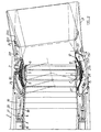
- Figure 1 shows, in axial section, an adjustable nozzle 2 fitted to the end of a fuselage or an aircraft nacelle 1.
- the post-combustion 3 or ejection channel is doubled towards the inside of a thermal protection jacket 4 which ends with a cylindrical surface 5.
- a cylindrical element 6 On the internal surface thereof, slides, under the action of the pressure of the cooling gases circulating between the channel 3 and the jacket 4, a cylindrical element 6 internally integral with a spherical ferrule 7 forming a hollow spherical ring.
- the outer surface of the ferrule 7 cooperates with a spherical surface 8 belonging to the movable part of the nozzle.
- the function of the hollow spherical ring is to prevent the cooling gases from escaping into the flow of the ejection gases and to bring them between the shell 7 and the sealing membrane 9 in order to cool the latter.
- the downstream end of the channel 3 is extended by a spherical surface 10.
- the movable part of the nozzle comprises a cylindrical shell 12 carrying upstream the inner spherical bearing 8 and an outer spherical bearing 11.
- the outer bearing 11 coaxially covers the inner bearing 8 and at least part of the cylindrical ferrule 12.
- the inner bearing 8 slides, as previously indicated, against the hollow spherical ring 7 to ensure the seal between the cooling gases and the ejected flow.
- the outer surface 11 carries the sealing membrane 9, which is fixed by one of its edges to the bearing part close to the cylindrical shell 12 and by its other edge to the free edge of the spherical bearing 10 of the fixed part.
- the outer spherical ferrule 11 is carried by a ferrule 13 fixed to the cylindrical ferrule 12.
- the movable part of the nozzle is held by an external spherical structure 14 whose rotation is controlled by a system of jacks.
- the seal between the outer spherical structure and the fuselage or the nacelle is ensured by a ring of elastic flaps 15 which bear against the structure.
- the actuators 16 controlling the rotation of the nozzle have their bodies housed in a fixed manner between the channel 3 and the fuselage or nacelle 1.
- the actuator rods come to act on the pads 17 integral with one of the ends of the rods 18 and which slide in the slides 19 of the fittings 20.
- the other ends of the links 18 are articulated to the structure 14.
- the jacks 16 can be of any type: hydraulic, pneumatic, screw, etc ... and act in traction or in push.
- the structure 14 carries at its downstream end the external flaps 21 of a device for modifying the end section of the rear body. These flaps are actuated by means of a link (not shown) articulated on the internal flaps 22, themselves of variable section and regulated by the jacks 23 fixed between the structure 14 and the flaps 22.
- the connection between the part mobile of the nozzle and the external spherical structure is obtained at least in part by the supports 24 of the jacks 23 which are integral with the shell 13 and the downstream end of the external structure 14.
- the device according to the invention relates inter alia to rolling means cooperating with the facing surfaces of two spherical bearings, one belonging to the fixed part and the other to the movable part of the orientable nozzle.
- a second external spherical bearing 25 is provided on the fixed part.
- the rolling means 26 are then placed between the outer spherical bearing 11 of the movable part and the outer spherical bearing 25 of the fixed part.
- the rolling means 26 consist of wheat held in a cage formed by two spherical rings made of tinsel of stainless steel comprising cells arranged in staggered rows in which the balls are housed.
- the rings are joined by known fixing means such as rivets, welding points, etc.
- the outer spherical bearing 25 of the fixed part is formed of two parts 251 and 252, the removable part 252 is fixed by its flange 253 to the flange 254 of the part 251 by bolting.
- the rolling means allow the forces undergone by the outer surface 11 of the movable part to be transmitted to the fixed part via the range 25 which can without disadvantages be provided with reinforcements on its outer wall.
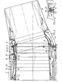
- FIG. 2 shows a second embodiment of the invention in which the ring of balls 26 is held between two honeycombed linings 27, 28, flexible, fixed on the fixed spherical bearings 25 and movable 11.
- the cells are distributed in staggered rows on the internal and external faces. These flexible elements are intended to dampen vibrations and to absorb dimensional differences due to the manufacturing tolerances of boilermaking assemblies. Between the facing faces of these flexible linings is placed the ring of balls (26).
- the means for guiding the movable part of the nozzle comprise a ramp 29 formed inside the outer spherical structure 14 of the movable nozzle and a roller 30 fixed by its axis on the outer surface of the outer spherical bearing 25 of the fixed part.
- the orientable nozzle represented in FIG. 2 is a diverging convergent nozzle.
- the cylindrical shell 12 is extended downstream by a modification device 220 of the section of the ejection nozzle.
- This device integral with the movable external structure 14 as regards the displacement of its axis, is capable of producing a diverging converging profile as shown in phantom.
- This modification is obtained as already described in document EP-A-29773 of November 23, 1979 in the name of the Applicant in a conventional manner using cylinders 221 and rods 222.
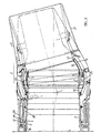
- FIG. 3 represents a third embodiment of the device in which the rolling means consist of a spherical lining 31 made of a material formed of a flat sheet on which is fixed a corrugated plate, by welding along the generatrices which constitute the summits of the undulations.
- the material is, for example, fixed on the outer spherical bearing 11 of the movable part.
- the top of the corrugations cooperating with the external spherical bearing 25 of the fixed part is formed concentric with the spherical bearing 11.
- the top of the corrugations is covered with a material with a low coefficient of friction, for example carbon or a composite material resistant to the heat.
- Pressing means 32 press on the external face of the external fixed spherical surface 25, which consists of portions of spheres joined together or overlapped.
- These means consist of rolling members, for example rollers mounted on levers 33 articulated at 34 on the external structure 14 of the movable part of the nozzle.
- the pressure of the roller on the bearing surface is determined by an elastic member 35 fixed between the structure 14 and the end of the lever 33 carrying the roller 32. This member 35 also acts as a shock absorber.
- the rollers are distributed equally along the periphery of the fixed bearing surface 25.
- the entire device ensures the recovery of part of the forces exerted on the nozzle, the other part of the forces being taken upstream by the action of the jacks 16.
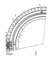
- the orientable nozzle also includes guide means, interposed between the pressure rollers, which are shown on the lower part of the figure and form an assembly comprising a slide 36 ( Figure 4) fixed on the spherical bearing outer 25 of the fixed part and a double action roller 37 fixed in the external structure 14 of the movable part.
- the double action rollers 37 consist of two off-center ball bearings 38 and 39, mounted on an axis 40, itself held by two ball bearings 41 in a bearing 42 fixed by flanges 43 on the part internal of the external structure 14 of the movable part of the nozzle.
- the means for guiding the orientable nozzle described above are similar to those of the orientable nozzle according to the first and second embodiments with the exception that the roller and slide elements are reversed relative to the bearing surface 25 of the part fixed and to the structure 14 of the movable part.
- Figures 6 and 7 show a fifth embodiment in which the rolling means consist of a deformable ring 47 which is fixed on the outer spherical bearing 11 of the movable part.
- This ring consists of a flexible membrane closed in a sealed volume occupying a significant part of the width of the bearing area pressurized using a valve 48 ( Figure 6).
- the ring 47 has the same role as the ring 44 of the previous example, that is to say ensuring the resumption of part of the forces of the movable part on the fixed part of the nozzle and the sealing between the gas jet and the cooling air.
- the S 50 profiles can advantageously be of a known type, for example with longitudinal slots and overlapping.
- the ends of the blades press and rub against a spherical part 51 secured to the support of the fixed bearing 25.
- these comprise three rollers 52 integral with the fixed part of the channel.
- the axes of two of the rollers are diametrically opposite with respect to the channel, while the axis of the third is perpendicular to the other two and arranged at the top of an isosceles triangle whose base passes through the other two.
- the movable part of the nozzle therefore rotates around two perpendicular axes, concurrent with the center of rotation.
- the geometric location of the axis of the movable nozzle for a maximum angular deflection value is constituted by a cone of 30 ° whose apex is located on the center of rotation. This value of 30 ° is moreover comparable to the deflection values of the other embodiments previously described.
- the rollers consist, as in the other embodiments, of two ball bearings 53, 54 rotating about an axis 55 secured to the fixed part 25 of the ejection channel.
- the rollers are in constant contact with the slide formed by two treads supported 56, 57 by two elastic members 58, 59 also playing the role of shock absorbers.
- the guide means consisting of three assemblies: rollers, treads and elastic members, are arranged in the external structure 14 of the movable part to which they are connected by the supports.
Landscapes
- Engineering & Computer Science (AREA)
- Chemical & Material Sciences (AREA)
- Combustion & Propulsion (AREA)
- Mechanical Engineering (AREA)
- General Engineering & Computer Science (AREA)
- Support Of The Bearing (AREA)
- Joints Allowing Movement (AREA)
- Spray Control Apparatus (AREA)
Applications Claiming Priority (2)
| Application Number | Priority Date | Filing Date | Title |
|---|---|---|---|
| FR8105460 | 1981-03-13 | ||
| FR8105460A FR2501786A1 (fr) | 1981-03-13 | 1981-03-13 | Dispositif de roulement et de guidage d'une tuyere orientable de propulseur a reaction |
Publications (3)
| Publication Number | Publication Date |
|---|---|
| EP0060763A1 EP0060763A1 (fr) | 1982-09-22 |
| EP0060763B1 EP0060763B1 (fr) | 1985-06-05 |
| EP0060763B2 true EP0060763B2 (fr) | 1989-01-04 |
Family
ID=9256395
Family Applications (1)
| Application Number | Title | Priority Date | Filing Date |
|---|---|---|---|
| EP82400393A Expired EP0060763B2 (fr) | 1981-03-13 | 1982-03-08 | Dispositif de roulement et de guidage d'une tuyère orientable de propulseur à réaction |
Country Status (4)
| Country | Link |
|---|---|
| US (1) | US4508270A (OSRAM) |
| EP (1) | EP0060763B2 (OSRAM) |
| DE (1) | DE3263993D1 (OSRAM) |
| FR (1) | FR2501786A1 (OSRAM) |
Families Citing this family (32)
| Publication number | Priority date | Publication date | Assignee | Title |
|---|---|---|---|---|
| FR2643947B1 (fr) * | 1989-03-01 | 1991-05-17 | Snecma | Ensemble d'ejection de turboreacteur a tuyere axisymetrique a section variable et a poussee orientable |
| US4978071A (en) * | 1989-04-11 | 1990-12-18 | General Electric Company | Nozzle with thrust vectoring in the yaw direction |
| US4994660A (en) * | 1989-04-11 | 1991-02-19 | Hitachi, Ltd. | Axisymmetric vectoring exhaust nozzle |
| US5039014A (en) * | 1989-04-11 | 1991-08-13 | General Electric Company | Axisymmetric vectoring exhaust nozzle seal |
| GB8927784D0 (en) * | 1989-12-08 | 1990-05-30 | Westland Helicopters | Helicopters |
| US5076496A (en) * | 1990-02-05 | 1991-12-31 | General Electric Company | Exhaust nozzle flap seal |
| US5150839A (en) * | 1991-03-14 | 1992-09-29 | General Electric Company | Nozzle load management |
| US5174502A (en) * | 1991-05-10 | 1992-12-29 | General Electric Company | Support for a translating nozzle vectoring ring |
| US5351888A (en) * | 1993-05-14 | 1994-10-04 | General Electric Company | Multi-axis vectorable exhaust nozzle |
| ES2105928B1 (es) * | 1993-09-21 | 1998-05-01 | Sener Ing & Sist | Petalo maestro divergente para toberas orientables de geometria variable destinadas a propulsores de turbina de gas. |
| RU2143577C1 (ru) * | 1998-03-20 | 1999-12-27 | Открытое акционерное общество "А.Люлька-Сатурн" | Устройство для сочленения наружной поверхности поворотного реактивного сопла двигателя и мотогондолы самолета |
| ES2153300B1 (es) * | 1998-09-04 | 2001-07-16 | Turbo Propulsores Ind | Mecanismo de guiado para toberas orientables de geometria variable aplicables a turbinas de gas. |
| FR2790791B1 (fr) | 1999-03-10 | 2001-04-13 | Snecma | Tuyere d'ejection de turboreacteur axisymetrique et a orientation globale |
| RU2162955C2 (ru) * | 1999-04-06 | 2001-02-10 | Открытое акционерное общество "Авиадвигатель" | Поворотное осесимметричное сопло |
| RU2162956C2 (ru) * | 1999-04-06 | 2001-02-10 | Открытое акционерное общество "Авиадвигатель" | Поворотное осесимметричное сопло |
| FR2792367B1 (fr) | 1999-04-15 | 2002-04-26 | Snecma | Tuyere d'ejection axisymetrique, convergente divergente a orientation par un anneau guide |
| FR2792366B1 (fr) * | 1999-04-15 | 2005-08-19 | Snecma | Tuyere d'ejection axisymetrique, convergente divergente et orientable |
| FR2792368B1 (fr) | 1999-04-19 | 2001-05-25 | Snecma | Tuyere d'ejection de turboreacteur a systeme d'orientation du type cardan |
| FR2796422B1 (fr) * | 1999-07-12 | 2001-09-07 | Snecma | Tuyere d'ejection de turboreacteur axisymetrique, convergente divergente a deviation de jet |
| US6546716B2 (en) * | 2001-04-26 | 2003-04-15 | Jean-Pierre Lair | Jet engine nozzle with variable thrust vectoring and exhaust area |
| US6938408B2 (en) * | 2001-04-26 | 2005-09-06 | Propulsion Vectoring, L.P. | Thrust vectoring and variable exhaust area for jet engine nozzle |
| RU2195564C1 (ru) * | 2001-07-31 | 2002-12-27 | Открытое акционерное общество Научно-производственное объединение "Искра" | Поворотное управляющее сопло ракетного двигателя |
| RU2310767C1 (ru) * | 2006-04-28 | 2007-11-20 | Открытое акционерное общество "Научно-производственное объединение "Сатурн" (ОАО "НПО "Сатурн") | Устройство для поворота реактивного сопла турбореактивного двигателя |
| DE102015015756B4 (de) * | 2015-12-04 | 2019-04-18 | Oleg Tchebunin | Triebwerk mit Frontluftkompressor, Dreistufiger Drehkolbenkraftmaschine mit kontinuierlichem Brennprozess und schwenkbaren Luftstrahldüsen als Antrieb für senkrechtstartende Flugzeuge |
| US11306681B2 (en) | 2019-01-15 | 2022-04-19 | The Boeing Company | Sheared exhaust nozzle |
| CN112572811B (zh) * | 2019-09-30 | 2022-07-15 | 林瑶章 | 飞行载具及其推进装置 |
| TWI715227B (zh) * | 2019-09-30 | 2021-01-01 | 林瑤章 | 飛行載具及其推進裝置 |
| US10837402B2 (en) * | 2020-01-09 | 2020-11-17 | Guanhao Wu | Thrust vector nozzle |
| CN111972639B (zh) * | 2020-08-28 | 2023-04-18 | 安徽雪域燕果食品有限公司 | 一种葡萄干回软设备及其回软加工方法 |
| EP4180332B1 (en) * | 2021-11-11 | 2025-01-08 | Airbus Defence and Space GmbH | Fuselage for an aircraft with fuselage-integrated tailplane |
| US11772809B2 (en) * | 2021-11-27 | 2023-10-03 | Airbus Defence and Space GmbH | Fuselage for an aircraft with fuselage-integrated tailplane |
| CN115853665B (zh) * | 2022-07-28 | 2023-12-22 | 宁波天擎航天科技有限公司 | 一种小型战术导弹用摆动喷管 |
Family Cites Families (14)
| Publication number | Priority date | Publication date | Assignee | Title |
|---|---|---|---|---|
| US2193375A (en) * | 1938-10-31 | 1940-03-12 | Adolph G Papritz | Airplane |
| FR1025827A (fr) * | 1950-10-11 | 1953-04-20 | Perfectionnement apporté aux engins aériens à réaction | |
| GB722338A (en) * | 1952-03-10 | 1955-01-26 | Rolls Royce | Improvements in or relating to jet reaction means |
| US3016697A (en) * | 1959-06-19 | 1962-01-16 | Curtiss Wright Corp | Rocket engine swivel mount |
| FR76840E (fr) * | 1960-01-06 | 1961-12-08 | Daimler Benz Ag | Réacteur à turbine à gaz avec brûleur monté en aval et tuyère de poussée, en particulier pour avions à décollage à la verticale et à décollage rapide |
| US3147591A (en) * | 1961-12-28 | 1964-09-08 | Gen Motors Corp | Swiveling fluid jet exhaust nozzle construction |
| GB1291586A (en) * | 1969-10-23 | 1972-10-04 | Rolls Royce | Propulsive jet nozzle assembly |
| US3912172A (en) * | 1971-05-07 | 1975-10-14 | Thiokol Corp | Self actuated pressure lubricated swivelled nozzle for rocket motors |
| US4047667A (en) * | 1975-07-10 | 1977-09-13 | Thiokol Corporation | Support system for rocket thrust nozzles |
| DE2719439C2 (de) * | 1977-04-30 | 1984-01-19 | Messerschmitt-Bölkow-Blohm GmbH, 8000 München | Schwenkbare Schubdüse zur Vektorsteuerung |
| US4108381A (en) * | 1977-06-06 | 1978-08-22 | Thiokol Corporation | Rocket nozzle bearing seal |
| DE2845149C2 (de) * | 1978-10-17 | 1982-03-04 | MTU Motoren- und Turbinen-Union München GmbH, 8000 München | Strahltriebwerk, insbesondere zum Antrieb eines Flugzeugs |
| DE2946324A1 (de) * | 1979-11-16 | 1981-06-04 | MTU Motoren- und Turbinen-Union München GmbH, 8000 München | Spaltabdichteinrichtung fuer eine schubstrahlablenkvorrichtung |
| FR2470253A1 (fr) * | 1979-11-23 | 1981-05-29 | Snecma | Tuyere orientable pour propulseur a reaction |
-
1981
- 1981-03-13 FR FR8105460A patent/FR2501786A1/fr active Granted
-
1982
- 1982-03-08 DE DE8282400393T patent/DE3263993D1/de not_active Expired
- 1982-03-08 EP EP82400393A patent/EP0060763B2/fr not_active Expired
- 1982-03-12 US US06/357,766 patent/US4508270A/en not_active Expired - Lifetime
Also Published As
| Publication number | Publication date |
|---|---|
| FR2501786B1 (OSRAM) | 1984-03-09 |
| US4508270A (en) | 1985-04-02 |
| EP0060763A1 (fr) | 1982-09-22 |
| DE3263993D1 (en) | 1985-07-11 |
| EP0060763B1 (fr) | 1985-06-05 |
| FR2501786A1 (fr) | 1982-09-17 |
Similar Documents
| Publication | Publication Date | Title |
|---|---|---|
| EP0060763B2 (fr) | Dispositif de roulement et de guidage d'une tuyère orientable de propulseur à réaction | |
| EP0029773B1 (fr) | Tuyère orientable pour propulseur à réaction | |
| EP2486247B1 (fr) | Dispositif de centrage et de guidage en rotation d'un arbre de turbomachine | |
| EP0155887B1 (fr) | Capotages structuraux participant à la rigidité d'ensemble d'un turboréacteur | |
| FR2676779A1 (fr) | Tuyere a section variable. | |
| EP4034776B1 (fr) | Ensemble de soufflante de turbomachine comprenant un roulement à rouleaux et un roulement à double rangée de billes à contact oblique | |
| EP1035316B1 (fr) | Tuyère d'éjection de turboréacteur axisymétrique et à orientation globale | |
| EP3149318B1 (fr) | Nacelle pour turboréacteur d'aéronef comprenant une tuyère secondaire à portes rotatives | |
| EP1507080A1 (fr) | Tuyère convergente divergente de turboréacteur | |
| FR2943749A1 (fr) | Bielle coudee equipee d'au moins un moyen d'auto-alignement | |
| EP0385834A1 (fr) | Ensemble d'éjection de Turboréacteur à tuyère axisymétrique à section variable et à poussée orientable | |
| EP1069302B1 (fr) | Tuyère d'éjection axisymétrique convergente divergente | |
| EP1068437B1 (fr) | Systeme d'activation de tuyere orientable pour propulseur a reaction utilisant plusieurs ensembles elastiques repartis circonferentiellement | |
| EP1068438B1 (fr) | Systeme d'activation de tuyere orientable par anneau elastique pour propulseur a reaction | |
| EP4392655A1 (fr) | Inverseur a grilles mobiles pour ensemble propulsif d'aeronef, comprenant un systeme pour limiter le flambage d'un actionneur de l'inverseur | |
| EP0313464B1 (fr) | Canal de transition d'un ensemble d'éjection de turboréacteur | |
| FR3161458A1 (fr) | Système annulaire de rétention d'un pointeau de tuyère | |
| FR3148060A1 (fr) | Agencement de conduit d’un flux d’air entre des carters annulaires d’un ensemble propulsif d’aeronef | |
| FR3053998A1 (fr) | Roue de turbomachine | |
| WO2024105332A1 (fr) | Inverseur de poussee comprenant une membrane d'obturation equipee d'un joint d'etancheite | |
| FR3145780A1 (fr) | Inverseur de poussee pour turbomachine d’aeronef comprenant des moyens de deploiement et de retrait a cable d’une membrane d’obturation de la veine secondaire | |
| FR2720108A1 (fr) | Echangeur thermique rotatif et turbine à gaz associée. | |
| FR2691425A1 (fr) | Carénage anti-vibrations pour un groupe d'accessoires juxtaposés embarqués sur un engin spatial tel qu'un lanceur. | |
| WO1995031685A1 (fr) | Echangeur thermique rotatif pour turbine a gaz associee |
Legal Events
| Date | Code | Title | Description |
|---|---|---|---|
| PUAI | Public reference made under article 153(3) epc to a published international application that has entered the european phase |
Free format text: ORIGINAL CODE: 0009012 |
|
| 17P | Request for examination filed |
Effective date: 19820312 |
|
| AK | Designated contracting states |
Designated state(s): DE FR GB |
|
| GRAA | (expected) grant |
Free format text: ORIGINAL CODE: 0009210 |
|
| AK | Designated contracting states |
Designated state(s): DE FR GB |
|
| REF | Corresponds to: |
Ref document number: 3263993 Country of ref document: DE Date of ref document: 19850711 |
|
| PLBI | Opposition filed |
Free format text: ORIGINAL CODE: 0009260 |
|
| 26 | Opposition filed |
Opponent name: MTU MOTOREN- UND TURBINEN-UNION MUENCHEN GMBH Effective date: 19860304 |
|
| PLAB | Opposition data, opponent's data or that of the opponent's representative modified |
Free format text: ORIGINAL CODE: 0009299OPPO |
|
| R26 | Opposition filed (corrected) |
Opponent name: MTU MOTOREN- UND TURBINEN-UNION MUENCHEN GMBH Effective date: 19860304 |
|
| PUAH | Patent maintained in amended form |
Free format text: ORIGINAL CODE: 0009272 |
|
| STAA | Information on the status of an ep patent application or granted ep patent |
Free format text: STATUS: PATENT MAINTAINED AS AMENDED |
|
| 27A | Patent maintained in amended form |
Effective date: 19890104 |
|
| AK | Designated contracting states |
Kind code of ref document: B2 Designated state(s): DE FR GB |
|
| PGFP | Annual fee paid to national office [announced via postgrant information from national office to epo] |
Ref country code: DE Payment date: 19990528 Year of fee payment: 18 |
|
| PGFP | Annual fee paid to national office [announced via postgrant information from national office to epo] |
Ref country code: FR Payment date: 20000203 Year of fee payment: 19 |
|
| PGFP | Annual fee paid to national office [announced via postgrant information from national office to epo] |
Ref country code: GB Payment date: 20000308 Year of fee payment: 19 |
|
| PG25 | Lapsed in a contracting state [announced via postgrant information from national office to epo] |
Ref country code: DE Free format text: LAPSE BECAUSE OF NON-PAYMENT OF DUE FEES Effective date: 20010103 |
|
| PG25 | Lapsed in a contracting state [announced via postgrant information from national office to epo] |
Ref country code: GB Free format text: LAPSE BECAUSE OF NON-PAYMENT OF DUE FEES Effective date: 20010308 |
|
| GBPC | Gb: european patent ceased through non-payment of renewal fee |
Effective date: 20010308 |
|
| PG25 | Lapsed in a contracting state [announced via postgrant information from national office to epo] |
Ref country code: FR Free format text: LAPSE BECAUSE OF NON-PAYMENT OF DUE FEES Effective date: 20011130 |
|
| REG | Reference to a national code |
Ref country code: FR Ref legal event code: ST |
|
| REG | Reference to a national code |
Ref country code: FR Ref legal event code: TP Ref country code: FR Ref legal event code: CD |