EP0060656A1 - Gaseous fuel and air metering device for an internal-combustion engine - Google Patents
Gaseous fuel and air metering device for an internal-combustion engine Download PDFInfo
- Publication number
- EP0060656A1 EP0060656A1 EP82301124A EP82301124A EP0060656A1 EP 0060656 A1 EP0060656 A1 EP 0060656A1 EP 82301124 A EP82301124 A EP 82301124A EP 82301124 A EP82301124 A EP 82301124A EP 0060656 A1 EP0060656 A1 EP 0060656A1
- Authority
- EP
- European Patent Office
- Prior art keywords
- air
- engine
- cylinders
- valve
- fuel
- Prior art date
- Legal status (The legal status is an assumption and is not a legal conclusion. Google has not performed a legal analysis and makes no representation as to the accuracy of the status listed.)
- Withdrawn
Links
- 239000000446 fuel Substances 0.000 title claims abstract description 96
- 238000002485 combustion reaction Methods 0.000 title claims abstract description 18
- 239000012530 fluid Substances 0.000 claims description 10
- 230000001276 controlling effect Effects 0.000 claims description 7
- 230000001105 regulatory effect Effects 0.000 claims description 7
- 239000000203 mixture Substances 0.000 claims description 4
- 239000002828 fuel tank Substances 0.000 description 3
- 239000003502 gasoline Substances 0.000 description 3
- 238000002347 injection Methods 0.000 description 3
- 239000007924 injection Substances 0.000 description 3
- 239000007788 liquid Substances 0.000 description 3
- 238000006243 chemical reaction Methods 0.000 description 2
- 239000003344 environmental pollutant Substances 0.000 description 2
- 239000007789 gas Substances 0.000 description 2
- 231100000719 pollutant Toxicity 0.000 description 2
- UFHFLCQGNIYNRP-UHFFFAOYSA-N Hydrogen Chemical compound [H][H] UFHFLCQGNIYNRP-UHFFFAOYSA-N 0.000 description 1
- 238000010276 construction Methods 0.000 description 1
- 230000008878 coupling Effects 0.000 description 1
- 238000010168 coupling process Methods 0.000 description 1
- 238000005859 coupling reaction Methods 0.000 description 1
- 230000007423 decrease Effects 0.000 description 1
- 238000006073 displacement reaction Methods 0.000 description 1
- 150000002431 hydrogen Chemical class 0.000 description 1
- 239000001257 hydrogen Substances 0.000 description 1
- 229910052739 hydrogen Inorganic materials 0.000 description 1
- 238000009434 installation Methods 0.000 description 1
- 230000001473 noxious effect Effects 0.000 description 1
- 239000002699 waste material Substances 0.000 description 1
Images
Classifications
-
- F—MECHANICAL ENGINEERING; LIGHTING; HEATING; WEAPONS; BLASTING
- F02—COMBUSTION ENGINES; HOT-GAS OR COMBUSTION-PRODUCT ENGINE PLANTS
- F02M—SUPPLYING COMBUSTION ENGINES IN GENERAL WITH COMBUSTIBLE MIXTURES OR CONSTITUENTS THEREOF
- F02M21/00—Apparatus for supplying engines with non-liquid fuels, e.g. gaseous fuels stored in liquid form
- F02M21/02—Apparatus for supplying engines with non-liquid fuels, e.g. gaseous fuels stored in liquid form for gaseous fuels
- F02M21/0218—Details on the gaseous fuel supply system, e.g. tanks, valves, pipes, pumps, rails, injectors or mixers
- F02M21/023—Valves; Pressure or flow regulators in the fuel supply or return system
- F02M21/0239—Pressure or flow regulators therefor
-
- Y—GENERAL TAGGING OF NEW TECHNOLOGICAL DEVELOPMENTS; GENERAL TAGGING OF CROSS-SECTIONAL TECHNOLOGIES SPANNING OVER SEVERAL SECTIONS OF THE IPC; TECHNICAL SUBJECTS COVERED BY FORMER USPC CROSS-REFERENCE ART COLLECTIONS [XRACs] AND DIGESTS
- Y02—TECHNOLOGIES OR APPLICATIONS FOR MITIGATION OR ADAPTATION AGAINST CLIMATE CHANGE
- Y02T—CLIMATE CHANGE MITIGATION TECHNOLOGIES RELATED TO TRANSPORTATION
- Y02T10/00—Road transport of goods or passengers
- Y02T10/10—Internal combustion engine [ICE] based vehicles
- Y02T10/30—Use of alternative fuels, e.g. biofuels
Definitions
- This invention relates to a device to meter the flow of gaseous fuel to an internal combustion engine.
- a carburetor or an electronic fuel injection system is used to supply fuel to the engine cylinders.
- Both types of devices fail to supply fuel and air in mixtures which are always completely combusted in the engine cylinders. This failure results in the waste of precious fuel and the exhaust of noxious pollutants. Further, emission control systems are required to deal with the pollutants from incompletely combusted fuel thereby adding to the cost of, and increasing the complexity of, the engine. with the supply of
- the invention is concerned fuel in a gaseous form and in correctly metered amounts to each individual cylinder of an internal combustion engine, and at the same time providing a precise amount of air to each cylinder.
- the gaseous fuel delivered in correctly etered amounts and mixed with air according to the engine load demand burns more completely. This provides better fuel economy and at the same time reduces pollution and the need for expensive and complex pollution control devices.
- the devices which incorporate the invention are of sturdy construction, have few moving parts, and are easily maintained.
- the vapor or combination vapor/air control device embodying the invention operates to meter fuel in gaseous forms such as LP gas, hydrogen, gasoline in a gaseous state, etc.
- the fuel is supplied by either a pressurized fuel tank as in the case of LP or hydrogen gas, or by a system which converts liquid gasoline into a gaseous state.
- Such conversion systems are well-known in the art and not a part of the invention.
- the fuel is supplied under a positive pressure to a reservoir chamber in the vapor control section of the device.
- the gaseous fuel in the reservoir chamber is metered out to the individual engine cylinders by first passing through valves to ) individual chambers equal in number to the number of engine cylinders.
- the fuel exits from the individual chambers either directly by a suction caused by the intake stroke of each cylinder or indirectly by the opening of a demand valve associated with each chamber which also operates by the suction caused by the intake stroke of the cylinder.
- a precise amount of fuel is metered to the individual chambers. This fuel is then released on demand to the cylinder associated with each individual chamber.
- a vapor control device is associated either with an existing carburetor in an internal combustion engine or with an air control unit. If a carburetor is used, it does not perform the function normally associated with it of mixing air and fuel.
- the function of either the carburetor or the air control unit is to meter or provide air to the intake port of a cylinder.
- the proper amount of air is supplied to each cylinder on its intake stroke by control via connections to the throttle of the engine and an air flap in the carburetor or air control unit and to a one-way air valve associated with each individual cylinder.
- the one-way air valve opens on the intake stroke of the cylinder to meter the necessary amount of air to be mixed in the intake port of the cylinder with the fuel delivered by the vapor control unit.
- the invention provides a means for metering a gaseous fuel and air to the cylinders of an internal combustion engine. It overcomes the problems associated with a conventional carburetor or fuel injection system which results in the inefficient combustion of fuel in the engine cyl- . inders. It thereby increases fuel economy and decreases the amount of pollution created by an engine.
- the vapor or combination vapor/air control device embodying the-invention additionally has the advantages of eliminating the problems encountered in carburization systems by which fuel may be transferred from one cylinder to another during the intake stroke of a cylinder.
- the unique metering system for .fuel and air does not provide fuel or air to each cylinder until its intake stroke.
- Both the fuel and the air.necessary for the complete combustion of the fuel in the engine cylinders are provided by separate systems and mixed at the inlet port to the cylinders. In.order that the air is delivered in adequate amounts to completely combust the fuel an interconnection between the fuel metering device and the air control device is essential to control the amount of air in the mixture to be combusted.
- the portion of the device responsible for controlling the flow of air to the cylinders of an internal combustion engine comprises an intake means connectable to the throttle of the engine and also connectable to the valve means of the vapor control unit for regulating the flow of air to one-way air valves associated with each individual cylinder of an internal combustion engine.
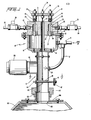
- the preferred embodiment of the vapor control unit is shown in Figure 1 and is represented generally by 10.
- the air control unit is generally referred to by 12.
- the vapor control unit receives fuel in a gaseous form under positive pressure through inlet 14 into a . reservoir 16.
- the reservoir 16 functions to maintain a sufficient supply of fuel for metering to the engine.
- Valves 18 are comprised of valve seats ,19, secured in ports 2 1 between the reservoir 16 and individual chambers 20, and valve seals 23.
- Each valve seal 23 has a frusto-conical shaped end 27 proximate the reservoir 16, a rod-shaped shaft 29 passing through a respective chamber 20 and channel 25 in the wall of chamber 20, and has an opposed threaded other end.
- the length of the tapered portion of the frusto-conical portion, the shaft and the rod-shaped end of each.valve seal 23 will vary depending on the size of the engine and thus on the desired flow requirements.
- valves 18 and associated individual chambers 20 are equal in number to the number of cylinders in the internal combustion engine with which the vapor control unit is used.
- Gaseous fuel exits the individual chambers 20 through outlets 22 in response to the opening and closing of demand valves 24, individually associated with each chamber 20.
- Each demand'valve 24 supplies the gaseous fuel through line 26 to a respective engine cylinder intake port.
- valves 18 which meter fuel from the reservoir 16 to the individual chambers 20 all are open and closed together in response to a connection to the engine throttle.
- each valve stem passes through and is adjustably secured to plate 28 by nuts 30.
- Plate 28 is adjustably secured to cable 32 by means of a threaded rod 34 and adjusting nuts 36.
- the cable 32 is attached at its opposite end to air flap 38 in air control unit 12.
- the air flap pivots about shaft 40 which is secured to drum 42. Cable 47 operatively interconnects drum 42 to the engine throttle.
- valves 18 are biased in a closed position by springs 44 disposed around shafts 29 between plate 28 and wall 31 of chamber 20.
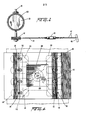
- Turnbuckle 46 on throttle cable 47 (Fig. 2), permits engine idle adjustment after installation of the vapor control unit.
- the idle adjustment by turnbuckle 46 maintains air flap 38 in a slightly open position and thereby pulls- down a cable 32 because of the offset position of the cable attached to the air 'flap as is best shown in Fig. 2.
- Valves 18 are adjusted accordingly and maintain a slightly open position to supply fuel to the ' demand valve. Adjustments are made to provide for the correct amounts of fuel and air for clean, efficient burning of all the fuel supplied to the engine cylinders by means of adjusting nuts 30 for valves 18 and by nuts 36 on threaded rod 34.
- air control unit 12 has air filter 100 in fluid communication with air intake 101 and has orifice 103 for supplying metered amounts of air to the intake manifold 102 oi the engine. Air entering the air control unit through the air filter 100 passes through air flap 38 in response to its opening and closing. The air flap position is regulated by the engine throttle. As shown in Fig. 1, the air control unit is secured to the intake manifold by means of coupling 104 which is affixed to bracket 106 mounted directly over opening 108 on the manifold 102.
- the fuel connections to the carburetor are eliminated, and the fuel is directed to the vapor control unit.
- the carburetor is used solely to meter air to the air manifold, thus performing the same function as the air control unit described.
- Distributor vacuum advance 120 is positoned below air flap 38 and is operatively connected to a distributor (not shown) to advance or retard the spark in response to engine load. This is .used when applicable to the type of distributor with which the engine is equipped. In some instances it is not necessary since some distributors are of the centrigual advance type and have no need for a connection with the air intake portion of the engine.
- air entering the intake manifold 102 passes through the inlet channels 110 to each cylinder.
- inlet channels 110 there are 8 separate passageways 110, leading to the 8 individual cylinders.
- the intake stroke of a cylinder creates a suction which opens the one-way air valve 112 to admit air from each passage 110 to the respective cylinder intake port.
- the suction created by the cylinder intake stroke opens a respective demand valve 24 and pulls gaseous fuel through line 26 into the respective cylinder. Since all of the valves 18 in the vapor control unit operate in unison, there is always a supply of fuel available in individual chambers 20 to feed any .individual engine cylinder. However, fuel in appropriate amounts in only released to a cylinder by the demand valves 24.
- the individual valves 18 control the rate at which gaseous fuel flows through the vapor control unit to the demand valves and thus control the amount of fuel which is permitted to flow to the engine when the demand valve is open on the intake stroke of a cylinder.
- the suction from the intake stroke of each cylinder acts through the fuel line 26, the individual chamber 20 and the reservoir 16 to open the demand valve to allow the necessary amount of fuel into the reservoir and direct it to the cylinder creating the demand.
- vapor control unit 10. and the air control unit 12 are mounted on an internal combustion engine 13.
- the air control unit 12 is in direct fluid communication with - manifold 102.
- the vapor control unit is connected to a fuel tank.
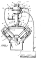
- Fig. 3 illustrates use of the device with a liquid fuel which becomes gaseous upon its expansion, such as LP gas.
- Fuel is released from tank 2 through a pressure regulator 3 and fuel line 4 to a second pressure regulator 5 which supplies gaseous fuel at a positive pressure to inlet 14 of vapor control unit 10.
- the pressure necessary depends upon engine displacement and the size of openings in the individual valves 18 but pressures in the range of 15 to 25 psi have been found acceptable.
- Both pressure regulators may be adjustable to control the delivery pressure of the fuel.
- a conversion system is used to produce a .gaseous form and to supply it under pressure.
- air line 17 which provides air from above the air flap 38 through fitting 29 in the air control unit or carburetor.
- air line 17 to fitting 15 has a valve with an adjustment such as a variable opening to restrict the flow of air and if a demand valve is usedit also is adjustable to i provide fuel in response to a predetermined level of suction. If a demand valve.is not positioned in fluid communication between inlet 14 and the fuel tank, as for example in the 8 cylinder engine of Fig.
- air line 17 is still necessary to eliminate the large negative engine pressure which otherwise acts on the one-way air valves. Although this air fitting introduces a small amount of air into the gaseous fuel entering the reservoir 16, it does not supply sufficient air to make a mixture which is completely combustible in accordance with this invention. If a demand valve is not used, some type of fuel shut-off valve must be used in the fuel line.
- Air filter 100 is in fluid communication with air control unit 12 at a position above air flap 38.
- the air flap is controlled by connection to cable 47 and throttle control 45.
- the throttle Upon operation of the throttle, as shown in Fig. 1, the air flap opens to admit air to the manifold and pulls on valve 32 which operates the valves of the v.apor control unit to release fuel to the individual chambers 20.
- Fuel in the individual chambers exits through a fuel line 26 and demand valve 24, in response to the intake stroke of a cylinder.
- Demand valves 24 may be positioned either adjacent the vapor control unit or elsewhere along the line between exit from the individual chambers in the vapor control unit and the cylinder inlet port.
- Air is pulled into the cylinder inlet port 114 from the manifold through one-way valves 112 and fuel enters from line 26 and demand valves 24 to be mixed with the air in the inlet port prior to entering the cylinder.
Landscapes
- Engineering & Computer Science (AREA)
- Chemical & Material Sciences (AREA)
- Chemical Kinetics & Catalysis (AREA)
- General Chemical & Material Sciences (AREA)
- Oil, Petroleum & Natural Gas (AREA)
- Combustion & Propulsion (AREA)
- Mechanical Engineering (AREA)
- General Engineering & Computer Science (AREA)
- Output Control And Ontrol Of Special Type Engine (AREA)
Applications Claiming Priority (2)
| Application Number | Priority Date | Filing Date | Title |
|---|---|---|---|
| US241838 | 1981-03-10 | ||
| US06/241,838 US4404947A (en) | 1981-03-10 | 1981-03-10 | Vapor/air control system |
Publications (1)
| Publication Number | Publication Date |
|---|---|
| EP0060656A1 true EP0060656A1 (en) | 1982-09-22 |
Family
ID=22912387
Family Applications (1)
| Application Number | Title | Priority Date | Filing Date |
|---|---|---|---|
| EP82301124A Withdrawn EP0060656A1 (en) | 1981-03-10 | 1982-03-05 | Gaseous fuel and air metering device for an internal-combustion engine |
Country Status (4)
| Country | Link |
|---|---|
| US (1) | US4404947A (enExample) |
| EP (1) | EP0060656A1 (enExample) |
| JP (1) | JPS57163135A (enExample) |
| CA (1) | CA1169312A (enExample) |
Cited By (3)
| Publication number | Priority date | Publication date | Assignee | Title |
|---|---|---|---|---|
| NL1000677C2 (nl) * | 1995-06-28 | 1996-12-31 | Combis B V | Inrichting geschikt voor het toevoeren van een gasvormige brandstof aan een verbrandingsmotor, alsmede verdamper, doseerinrichting, processor en drukregelinrichting geschikt voor een dergelijke inrichting. |
| EP0863300A1 (en) * | 1997-03-06 | 1998-09-09 | Florgas di Dall'Aglio, Loris | Equipment for feeding an internal combustion engine with a gaseous fuel |
| CN103477060A (zh) * | 2011-04-01 | 2013-12-25 | 氢能源系统有限责任公司 | 混合块 |
Families Citing this family (10)
| Publication number | Priority date | Publication date | Assignee | Title |
|---|---|---|---|---|
| US5370098A (en) * | 1991-04-20 | 1994-12-06 | Yamaha Hatsudoki Kabushiki Kaisha | Air intake system for gas fueled engine |
| US5337722A (en) * | 1992-04-16 | 1994-08-16 | Yamaha Hatsudoki Kabushiki Kaisha | Fuel control and feed system for gas fueled engine |
| US5546919A (en) * | 1993-08-31 | 1996-08-20 | Yamaha Hatsudoki Kabushiki Kaisha | Operating arrangement for gaseous fueled engine |
| US5575266A (en) * | 1993-08-31 | 1996-11-19 | Yamaha Hatsudoki Kabushiki Kaisha | Method of operating gaseous fueled engine |
| JP3139592B2 (ja) * | 1993-08-31 | 2001-03-05 | ヤマハ発動機株式会社 | ガス燃料エンジンの混合気形成装置 |
| JPH07253049A (ja) * | 1994-03-14 | 1995-10-03 | Yamaha Motor Co Ltd | 気体燃料エンジン用燃料供給装置 |
| JPH07253048A (ja) * | 1994-03-15 | 1995-10-03 | Yamaha Motor Co Ltd | ガス燃料エンジンの混合気形成方法及び装置 |
| US5463997A (en) * | 1994-10-05 | 1995-11-07 | Cutler Induction Systems, Inc. | Single point fuel injection system |
| US5666927A (en) * | 1996-07-26 | 1997-09-16 | Siemens Automotive Corporation | Fuel/air supply system for a fuel injector and methods of operation |
| US12448939B1 (en) * | 2024-04-18 | 2025-10-21 | Caterpillar Inc. | Fuel admission tube for enhanced mixing in gaseous fuel engine and engine operating method |
Citations (4)
| Publication number | Priority date | Publication date | Assignee | Title |
|---|---|---|---|---|
| BE398335A (enExample) * | ||||
| US3073686A (en) * | 1958-08-27 | 1963-01-15 | Harold D Harris | Gas carburetor |
| US3799124A (en) * | 1972-05-05 | 1974-03-26 | Pollution Free Power Corp | Hydrogen engine and method of fueling same |
| US3960126A (en) * | 1974-01-12 | 1976-06-01 | Toyota Jidosha Kogyo Kabushiki Kaisha | Pressure regulator of liquefied-gas fuel system for internal combustion engines |
Family Cites Families (17)
| Publication number | Priority date | Publication date | Assignee | Title |
|---|---|---|---|---|
| US2505725A (en) * | 1946-12-23 | 1950-04-25 | Nat Supply Co | Gas fuel mixer for internalcombustion engines |
| US2571713A (en) * | 1949-12-16 | 1951-10-16 | Jerome E Domengeaux | Gas timing and metering valve |
| US2939776A (en) * | 1957-07-22 | 1960-06-07 | Weldon G Carver | Pressure type carburetor |
| US2999674A (en) * | 1958-09-29 | 1961-09-12 | Harry W Mcclain | Fuel carburetor with central air intake |
| US2956791A (en) * | 1958-11-28 | 1960-10-18 | Charles E Johnson | Carburetor |
| US3116988A (en) * | 1961-10-23 | 1964-01-07 | Int Comb Res Company | Fuel vaporizing assembly |
| US3265374A (en) * | 1963-08-14 | 1966-08-09 | Glenn R Morton | Carburetor for internal combustion engines |
| US3475011A (en) * | 1967-01-12 | 1969-10-28 | Trw Inc | Individual intake port carburetion system |
| US4026258A (en) * | 1969-02-10 | 1977-05-31 | Mitsubishi Jidosha Kogyo Kabushiki Kaisha | Control device for regulating the amount of collected fuel and/or oil vapors which are delivered to the combustion chamber of an internal combustion |
| US3630698A (en) * | 1970-01-21 | 1971-12-28 | Joseph H Baldwin | Fuel system |
| US3651794A (en) * | 1970-06-15 | 1972-03-28 | Victor Equipment Co | Throttle for gaseous fuels |
| DE2054911A1 (de) * | 1970-11-07 | 1972-05-10 | Robert Bosch Gmbh, 7000 Stuttgart | Regelorgan für eine Kraftstoffeinspritzanlage |
| US3846094A (en) * | 1972-07-25 | 1974-11-05 | Impco Carburetion Inc | Air-gas mixing device |
| NL7215280A (enExample) * | 1972-11-10 | 1974-05-14 | ||
| US3970059A (en) * | 1975-04-30 | 1976-07-20 | Pisar Robert J | Engine speed control for an internal combustion engine adapted for operation with L.P. gas |
| US4020810A (en) * | 1975-10-08 | 1977-05-03 | Impco Carburetion, Inc. | Economizer valve for use with gas-powered internal combustion engines |
| US4106453A (en) * | 1976-08-02 | 1978-08-15 | Burley Ernest G | Apparatus and process for improving fuel efficiency of an internal combustion engine utilizing a vapor state of fuel |
-
1981
- 1981-03-10 US US06/241,838 patent/US4404947A/en not_active Expired - Lifetime
-
1982
- 1982-02-26 CA CA000397235A patent/CA1169312A/en not_active Expired
- 1982-03-05 EP EP82301124A patent/EP0060656A1/en not_active Withdrawn
- 1982-03-05 JP JP57035020A patent/JPS57163135A/ja active Granted
Patent Citations (4)
| Publication number | Priority date | Publication date | Assignee | Title |
|---|---|---|---|---|
| BE398335A (enExample) * | ||||
| US3073686A (en) * | 1958-08-27 | 1963-01-15 | Harold D Harris | Gas carburetor |
| US3799124A (en) * | 1972-05-05 | 1974-03-26 | Pollution Free Power Corp | Hydrogen engine and method of fueling same |
| US3960126A (en) * | 1974-01-12 | 1976-06-01 | Toyota Jidosha Kogyo Kabushiki Kaisha | Pressure regulator of liquefied-gas fuel system for internal combustion engines |
Cited By (5)
| Publication number | Priority date | Publication date | Assignee | Title |
|---|---|---|---|---|
| NL1000677C2 (nl) * | 1995-06-28 | 1996-12-31 | Combis B V | Inrichting geschikt voor het toevoeren van een gasvormige brandstof aan een verbrandingsmotor, alsmede verdamper, doseerinrichting, processor en drukregelinrichting geschikt voor een dergelijke inrichting. |
| WO1997001701A1 (en) * | 1995-06-28 | 1997-01-16 | Indopar B.V. | Gaseous fuel supply device for an internal combustion engine |
| US6178952B1 (en) | 1995-06-28 | 2001-01-30 | Indopar B.V. | Gaseous fuel supply device for an internal combustion engine |
| EP0863300A1 (en) * | 1997-03-06 | 1998-09-09 | Florgas di Dall'Aglio, Loris | Equipment for feeding an internal combustion engine with a gaseous fuel |
| CN103477060A (zh) * | 2011-04-01 | 2013-12-25 | 氢能源系统有限责任公司 | 混合块 |
Also Published As
| Publication number | Publication date |
|---|---|
| US4404947A (en) | 1983-09-20 |
| CA1169312A (en) | 1984-06-19 |
| JPH0321734B2 (enExample) | 1991-03-25 |
| JPS57163135A (en) | 1982-10-07 |
Similar Documents
| Publication | Publication Date | Title |
|---|---|---|
| US3931814A (en) | Cylinder-induction responsive electronic fuel feed control carburetors | |
| US4404947A (en) | Vapor/air control system | |
| EP0112918B1 (en) | Control valve for a gas fuel supply to an internal combustion engine and method for using the control valve | |
| EP0933518A2 (en) | Mixer plate for an internal combustion engine | |
| US4453523A (en) | Pressure balanced flow regulator for gaseous fuel engine | |
| US4513727A (en) | Process for controlling secondary gas fuel to normally liquid fueled I.C. engine | |
| JP2550026B2 (ja) | 内燃機関の液体燃料分配方法および分配装置 | |
| US4387695A (en) | Fuel injection apparatus | |
| KR970001930A (ko) | 연료와 공기 혼합물을 형성하기 위한 방법 및 내연 기관에 이용되는 연료 공급 장치 | |
| US3710770A (en) | Fuel system | |
| US4348338A (en) | Injection-type pressure-freed carburetor | |
| EP0363448A1 (en) | FLUID SERVO-SYSTEM FOR FUEL INJECTION AND OTHER APPLICATIONS. | |
| US6186117B1 (en) | Electronic compensation system | |
| GB1263777A (en) | Internal combustion engine charge formation and induction system | |
| US5827335A (en) | Enhanced performance carburetor system | |
| PL91405B1 (enExample) | ||
| US5027783A (en) | Carburetor for an internal combustion engine | |
| US3789812A (en) | Air/fuel mixing system controlled by temperature activated mechanism for internal combustion engines | |
| US3953547A (en) | Carburetor | |
| US3023745A (en) | Supplemental air by-pass system for internal combustion engines | |
| GB2043785A (en) | Carburettor unit for a multicylinder internal combustion engine | |
| US5462024A (en) | Auxiliary carburetion device in direct fuel injection engines | |
| US3475011A (en) | Individual intake port carburetion system | |
| NL8600611A (nl) | Gasinstallatie voor toepassing in verbrandingsmotoren. | |
| RU2022148C1 (ru) | Система питания газообразным топливом для многоцилиндрового двигателя внутреннего сгорания |
Legal Events
| Date | Code | Title | Description |
|---|---|---|---|
| PUAI | Public reference made under article 153(3) epc to a published international application that has entered the european phase |
Free format text: ORIGINAL CODE: 0009012 |
|
| AK | Designated contracting states |
Designated state(s): DE FR GB SE |
|
| 17P | Request for examination filed |
Effective date: 19830322 |
|
| STAA | Information on the status of an ep patent application or granted ep patent |
Free format text: STATUS: THE APPLICATION IS DEEMED TO BE WITHDRAWN |
|
| 18D | Application deemed to be withdrawn |
Effective date: 19840612 |