EP0060193B1 - Dispositif de traitement de l'eau par impulsions électriques à gradation de puissance - Google Patents
Dispositif de traitement de l'eau par impulsions électriques à gradation de puissance Download PDFInfo
- Publication number
- EP0060193B1 EP0060193B1 EP82400374A EP82400374A EP0060193B1 EP 0060193 B1 EP0060193 B1 EP 0060193B1 EP 82400374 A EP82400374 A EP 82400374A EP 82400374 A EP82400374 A EP 82400374A EP 0060193 B1 EP0060193 B1 EP 0060193B1
- Authority
- EP
- European Patent Office
- Prior art keywords
- discharge
- flow
- circuit
- capacitor
- rate
- Prior art date
- Legal status (The legal status is an assumption and is not a legal conclusion. Google has not performed a legal analysis and makes no representation as to the accuracy of the status listed.)
- Expired
Links
- XLYOFNOQVPJJNP-UHFFFAOYSA-N water Substances O XLYOFNOQVPJJNP-UHFFFAOYSA-N 0.000 title claims abstract description 10
- 239000003990 capacitor Substances 0.000 claims abstract description 38
- 239000007788 liquid Substances 0.000 claims abstract description 15
- 230000002093 peripheral effect Effects 0.000 claims abstract description 7
- 239000004020 conductor Substances 0.000 description 6
- 238000005259 measurement Methods 0.000 description 3
- 230000008878 coupling Effects 0.000 description 2
- 238000010168 coupling process Methods 0.000 description 2
- 238000005859 coupling reaction Methods 0.000 description 2
- 238000000034 method Methods 0.000 description 2
- 230000008569 process Effects 0.000 description 2
- 230000009471 action Effects 0.000 description 1
- 230000015572 biosynthetic process Effects 0.000 description 1
- 230000008859 change Effects 0.000 description 1
- 238000004140 cleaning Methods 0.000 description 1
- 238000007599 discharging Methods 0.000 description 1
- 230000000737 periodic effect Effects 0.000 description 1
- 230000000135 prohibitive effect Effects 0.000 description 1
Images
Classifications
-
- C—CHEMISTRY; METALLURGY
- C02—TREATMENT OF WATER, WASTE WATER, SEWAGE, OR SLUDGE
- C02F—TREATMENT OF WATER, WASTE WATER, SEWAGE, OR SLUDGE
- C02F1/00—Treatment of water, waste water, or sewage
- C02F1/48—Treatment of water, waste water, or sewage with magnetic or electric fields
-
- C—CHEMISTRY; METALLURGY
- C02—TREATMENT OF WATER, WASTE WATER, SEWAGE, OR SLUDGE
- C02F—TREATMENT OF WATER, WASTE WATER, SEWAGE, OR SLUDGE
- C02F1/00—Treatment of water, waste water, or sewage
- C02F1/46—Treatment of water, waste water, or sewage by electrochemical methods
- C02F1/461—Treatment of water, waste water, or sewage by electrochemical methods by electrolysis
- C02F1/46104—Devices therefor; Their operating or servicing
-
- C—CHEMISTRY; METALLURGY
- C02—TREATMENT OF WATER, WASTE WATER, SEWAGE, OR SLUDGE
- C02F—TREATMENT OF WATER, WASTE WATER, SEWAGE, OR SLUDGE
- C02F2201/00—Apparatus for treatment of water, waste water or sewage
- C02F2201/002—Construction details of the apparatus
- C02F2201/003—Coaxial constructions, e.g. a cartridge located coaxially within another
-
- C—CHEMISTRY; METALLURGY
- C02—TREATMENT OF WATER, WASTE WATER, SEWAGE, OR SLUDGE
- C02F—TREATMENT OF WATER, WASTE WATER, SEWAGE, OR SLUDGE
- C02F2201/00—Apparatus for treatment of water, waste water or sewage
- C02F2201/46—Apparatus for electrochemical processes
- C02F2201/461—Electrolysis apparatus
- C02F2201/46105—Details relating to the electrolytic devices
- C02F2201/4612—Controlling or monitoring
- C02F2201/46125—Electrical variables
- C02F2201/4613—Inversing polarity
-
- C—CHEMISTRY; METALLURGY
- C02—TREATMENT OF WATER, WASTE WATER, SEWAGE, OR SLUDGE
- C02F—TREATMENT OF WATER, WASTE WATER, SEWAGE, OR SLUDGE
- C02F2201/00—Apparatus for treatment of water, waste water or sewage
- C02F2201/46—Apparatus for electrochemical processes
- C02F2201/461—Electrolysis apparatus
- C02F2201/46105—Details relating to the electrolytic devices
- C02F2201/4612—Controlling or monitoring
- C02F2201/46145—Fluid flow
-
- C—CHEMISTRY; METALLURGY
- C02—TREATMENT OF WATER, WASTE WATER, SEWAGE, OR SLUDGE
- C02F—TREATMENT OF WATER, WASTE WATER, SEWAGE, OR SLUDGE
- C02F2201/00—Apparatus for treatment of water, waste water or sewage
- C02F2201/46—Apparatus for electrochemical processes
- C02F2201/461—Electrolysis apparatus
- C02F2201/46105—Details relating to the electrolytic devices
- C02F2201/4616—Power supply
- C02F2201/46175—Electrical pulses
Definitions
- the present invention relates to a device for treating a liquid, such as distributed water, of the type allowing the repeated passage of a discharge current from a capacitor between two electrodes immersed in a treatment chamber through which the liquid passes.
- this frequency is of the order of 16 Hz, a frequency ensuring maximum efficiency in the treatment of the liquid.
- a contactor actuated by the circulating liquid makes it possible to put the device into operation only when there is a flow of liquid.
- Such a device is described in particular in FR-A-2 312 017.
- the present invention provides a processing device of the aforementioned type, making it possible to scale the power delivered as a function of the flow rate.
- the device comprises a capacitor bank
- the means capable of varying the power comprise a circuit making it possible to modify the value of the total capacity of said capacitors as a function of the flow rate.
- the present invention is provided with circuits making it possible to periodically reverse the direction of charge of the armature of the capacitor which will be connected to the central electrode of the treatment chamber.
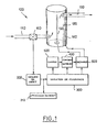
- the water circulation circuit 100 composed of an inlet pipe 110, a treatment chamber 120, and an outlet pipe 130.
- the shape of the treatment chamber is substantially cylindrical, its outer envelope is metallic and constitutes the peripheral electrode 140.
- the other electrode 150 is arranged axially inside the treatment chamber.
- a flow sensor 160 is inserted into the input circuit to provide an electrical signal proportional to the flow of liquid.
- the electrical circuit is composed of a flow measurement circuit 200 making it possible to process the signal coming from the sensor 160, and being able to control a display circuit 210 displaying the measured value of the flow, of a power variation circuit 300 in function of the flow receiving the information supplied by the flow measurement circuit 200, a capacitor 400 charged by a charge circuit 500 and capable of being discharged between the two electrodes 140 and 150 via a discharge circuit 600.
- the circuit 300 makes it possible to modify the parameters of the charge and the discharge in order to vary the total power delivered to the treatment chamber 120.
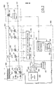
- FIG. 2 shows a preferred embodiment of the device.
- the measurement circuit of flow 200 has a plurality of logic outputs 201, 202, ... 203, 204 such that the number of outputs in state »1« is a function of the flow measured by the sensor.
- the display circuit 210 is connected to these outputs, and can for example be made up of as many light-emitting diodes as there are logic outputs, each diode indicating the logic state of the output to which it is connected. The number of diodes lit thus gives an indication of the value of the liquid flow rate.
- the outputs 201 ... 204 are connected to the inputs 301 ... 304 of a capacitor selection circuit, actuating the triggers of a plurality of triacs 411 ...
- Each triac is connected on the one hand to a first common conductor 420, on the other hand to the armature of a capacitor 401 ... 404 whose other armature is connected to a second common conductor 430
- the capacitors 401 ... 404 are charged by means of the circuit 500 consisting of a transformer 501 connected on the one hand directly to the conductor 430, on the other hand to the conductor 420 via a circuit formed by two branches parallel, each branch comprising a diode 511 or 512 in series with a triac 521 or 522, the two diodes being mounted in different directions in each of the two branches.
- the capacitors are discharged between the electrodes 140 and 150 by a triac 610 which can be made conductive by the action of a coupling circuit 620 actuating its trigger.
- the charge and discharge cycles are controlled by a fixed frequency pulse generator 310 the output of which is connected, on the one hand to the coupling circuit 620 actuating the triac 610, on the other hand to a counter 320 triggering a flip-flop whose the outputs 321 and 322 are connected to the triggers of the triacs 521 and 522 of the charging circuit.
- the logic outputs 201 ... 204 are activated in greater or lesser number. In the absence of flow they are all in the state »0«, for a low flow only the output 201 is in the state »1 «, when the flow increases the two outputs 201 and 202 pass to the state » 1 ", ... ,, and for the maximum flow rate all of the outputs 201 ... 204 are in the state" 1 ".
- These outputs will make a greater or lesser number of triacs 411 ... 414 conductive. For zero or very low flow all the triacs are blocked, for the maximum flow they are all conductive.
- Such a circuit therefore makes it possible to switch a variable number of capacitors 401 ... 404 according to the measured flow rate. By increasing the capacity, the energy released in the treatment chamber is increased.
- all the capacitors 401 ... 404 have the same value, thus allowing linear progression of the capacity, but it is possible to imagine other variants without thereby departing from the scope of the invention.
- a variant consists in switching only one capacitor at a time, but in having a capacitor bank of increasing capacitances, the capacitor 401 having for example the lowest capacitance, the capacitor 404, the most capacitance high.
- the triacs 521 and 522 are controlled by the circuit 320 , so that one of them is conductive when the other is blocked.
- the conductor 420 will be brought to a positive potential with respect to the conductor 430. Otherwise, it will be at negative potential. It is thus possible, by controlling the triacs 521 and 522, to alternate the direction of charge of the capacitor 400, therefore changing the polarity of the discharge pulses in the electrodes 140 and 150.
- the discharge takes place by making the triac 610 conductive; the capacitor 400 can thus discharge between the electrodes 140 and 150 at each pulse delivered by the generator 310. These pulses will also serve as clock pulses for the counter 320 which causes, after a given time, the change of state of a flip-flop whose inverted outputs 321 and 322 will control the triacs 521 and 522. It is thus possible, for example every half hour, to cause the automatic reversal of the direction of charge of the capacitors.
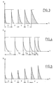
- FIG. 3 shows the shape of the pulses delivered to the electrodes for increasing values of the flow rate. Time is plotted on the abscissa, the discharge voltage is plotted on the ordinate. We see that, of the three parameters: repetition frequency, charge voltage, and capacitor capacitor, the first two values remain constant but that, by increasing the capacitance, we thereby increase the energy supplied, proportional to the hatched area.
- FIG. 4 refers to a possible variant of the device, where a single capacitor, charged at constant voltage, is used instead of the capacitor bank 400, but where the frequency of the pulse generator 310 is varied as a function of the flow, the repetition of the pulses being faster for higher flow rates.
- the energy of each discharge is constant, but the total power, equal to the total energy (number of pulses x energy of a pulse) divided by time, increases with the flow.
- Figure 5 shows the pulses that one could have by varying the charge voltage as a function of the flow, at constant frequency and capacity:
- the energy of each discharge here again represented by the hatched area, increases in proportion to the flow d 'water.
Landscapes
- Chemical & Material Sciences (AREA)
- Organic Chemistry (AREA)
- Engineering & Computer Science (AREA)
- Environmental & Geological Engineering (AREA)
- Water Supply & Treatment (AREA)
- Hydrology & Water Resources (AREA)
- Life Sciences & Earth Sciences (AREA)
- Chemical Kinetics & Catalysis (AREA)
- Electrochemistry (AREA)
- General Chemical & Material Sciences (AREA)
- Water Treatment By Electricity Or Magnetism (AREA)
- Silver Salt Photography Or Processing Solution Therefor (AREA)
- Treatments Of Macromolecular Shaped Articles (AREA)
- Cleaning And De-Greasing Of Metallic Materials By Chemical Methods (AREA)
Priority Applications (1)
| Application Number | Priority Date | Filing Date | Title |
|---|---|---|---|
| AT82400374T ATE12035T1 (de) | 1981-03-06 | 1982-03-04 | Vorrichtung zur behandlung von wasser mittels elektrischer impulse mit veraenderlicher stromstaerke. |
Applications Claiming Priority (2)
| Application Number | Priority Date | Filing Date | Title |
|---|---|---|---|
| FR8104510 | 1981-03-06 | ||
| FR8104510A FR2501184A1 (fr) | 1981-03-06 | 1981-03-06 | Dispositif de traitement de l'eau par impulsions electriques a gradation de puissance |
Publications (2)
| Publication Number | Publication Date |
|---|---|
| EP0060193A1 EP0060193A1 (fr) | 1982-09-15 |
| EP0060193B1 true EP0060193B1 (fr) | 1985-03-06 |
Family
ID=9255947
Family Applications (1)
| Application Number | Title | Priority Date | Filing Date |
|---|---|---|---|
| EP82400374A Expired EP0060193B1 (fr) | 1981-03-06 | 1982-03-04 | Dispositif de traitement de l'eau par impulsions électriques à gradation de puissance |
Country Status (6)
| Country | Link |
|---|---|
| EP (1) | EP0060193B1 (enExample) |
| AT (1) | ATE12035T1 (enExample) |
| DE (1) | DE3262483D1 (enExample) |
| ES (1) | ES8301843A1 (enExample) |
| FR (1) | FR2501184A1 (enExample) |
| PT (1) | PT74464B (enExample) |
Cited By (1)
| Publication number | Priority date | Publication date | Assignee | Title |
|---|---|---|---|---|
| RU2337070C2 (ru) * | 2003-03-20 | 2008-10-27 | Государственное образовательное учреждение высшего профессионального образования Уфимский Государственный Нефтяной Технический Университет (УГНТУ) | Способ очистки природных и сточных вод и устройство для его осуществления |
Families Citing this family (12)
| Publication number | Priority date | Publication date | Assignee | Title |
|---|---|---|---|---|
| FR2579195B1 (fr) * | 1985-04-17 | 1990-09-28 | Heuschling Raymond | Appareil pour la formation de polymeres de l'eau en vue d'effets biologiques et catalytiques avec et sans ions metalliques |
| DE3808393A1 (de) * | 1988-03-12 | 1989-09-21 | Westfael Elekt Werke | Verfahren zur elektrochemischen behandlung von waessern |
| FR2630100B1 (fr) | 1988-04-15 | 1991-11-08 | Freyne Claude | Procede et dispositif de traitement de l'eau du reseau de distribution par impulsions electriques a duree modulee |
| JP2668087B2 (ja) * | 1989-05-02 | 1997-10-27 | 株式会社イナックス | イオン水生成器の濃度設定装置 |
| JP3149138B2 (ja) * | 1991-10-09 | 2001-03-26 | ミズ株式会社 | 連続式電解イオン水生成器の制御装置 |
| JP2810262B2 (ja) * | 1991-10-11 | 1998-10-15 | ミズ株式会社 | 連続式電解イオン水生成器の制御装置 |
| EP0569596A4 (en) * | 1991-11-22 | 1993-12-22 | Techno Excel Kabushiki Kaisha | Apparatus for generating electrolytic water |
| RU2174960C1 (ru) * | 2000-10-18 | 2001-10-20 | Банников Владимир Васильевич | Устройство для обработки воды (варианты) |
| RU2219136C2 (ru) * | 2002-02-18 | 2003-12-20 | Научно-исследовательский институт интроскопии при Томском политехническом университете | Способ и устройство очистки жидких и газообразных сред |
| RU2262487C1 (ru) * | 2004-05-18 | 2005-10-20 | Рутберг Филипп Григорьевич | Установка для обеззараживания воды электрическими разрядами |
| RU2362616C1 (ru) * | 2008-07-02 | 2009-07-27 | Государственное образовательное учреждение высшего профессионального образования "Московский государственный университет прикладной биотехнологии" | Устройство для диспергирования эмульсий и суспензий с регулированием размеров частиц дисперсных фаз |
| EP3348521A1 (en) * | 2017-01-12 | 2018-07-18 | Dymond Cleantech | Process of electrochemical oxidation |
Family Cites Families (8)
| Publication number | Priority date | Publication date | Assignee | Title |
|---|---|---|---|---|
| BE405508A (enExample) * | 1933-10-06 | |||
| CH201629A (de) * | 1938-02-14 | 1938-12-15 | Pulso & Technik A G | Verfahren zur Verhinderung der Bildung von Kesselstein in Behältern. |
| GB601579A (en) * | 1945-06-05 | 1948-05-07 | Dubilier Condenser Co 1925 Ltd | Improvements in or relating to apparatus for electrically treating fluids |
| LU36227A1 (enExample) * | 1957-07-08 | |||
| CH501193A (de) * | 1968-12-18 | 1970-12-31 | Guldager Electrolyse Internat | Elektrolytische Warmwasserbehandlungsanlage |
| FR2057332A5 (enExample) * | 1969-08-12 | 1971-05-21 | Arieta Araunabena Ruiz D | |
| FR2312017A1 (fr) * | 1975-05-23 | 1976-12-17 | Clement Daniel | Detecteur d'ecoulement |
| DE2846452A1 (de) * | 1978-10-25 | 1980-05-08 | Inst Biomedizinische Technik | Elektrische versorgung fuer wasseraufbereitungszellen nach dem verfahren der anodischen oxidation |
-
1981
- 1981-03-06 FR FR8104510A patent/FR2501184A1/fr active Granted
-
1982
- 1982-02-19 PT PT74464A patent/PT74464B/pt unknown
- 1982-03-04 DE DE8282400374T patent/DE3262483D1/de not_active Expired
- 1982-03-04 EP EP82400374A patent/EP0060193B1/fr not_active Expired
- 1982-03-04 AT AT82400374T patent/ATE12035T1/de not_active IP Right Cessation
- 1982-03-05 ES ES510708A patent/ES8301843A1/es not_active Expired
Cited By (1)
| Publication number | Priority date | Publication date | Assignee | Title |
|---|---|---|---|---|
| RU2337070C2 (ru) * | 2003-03-20 | 2008-10-27 | Государственное образовательное учреждение высшего профессионального образования Уфимский Государственный Нефтяной Технический Университет (УГНТУ) | Способ очистки природных и сточных вод и устройство для его осуществления |
Also Published As
| Publication number | Publication date |
|---|---|
| EP0060193A1 (fr) | 1982-09-15 |
| ES510708A0 (es) | 1983-02-01 |
| ES8301843A1 (es) | 1983-02-01 |
| DE3262483D1 (en) | 1985-04-11 |
| PT74464A (fr) | 1982-03-01 |
| ATE12035T1 (de) | 1985-03-15 |
| FR2501184A1 (fr) | 1982-09-10 |
| PT74464B (fr) | 1983-09-27 |
| FR2501184B1 (enExample) | 1985-03-08 |
Similar Documents
| Publication | Publication Date | Title |
|---|---|---|
| EP0060193B1 (fr) | Dispositif de traitement de l'eau par impulsions électriques à gradation de puissance | |
| FR2605415A1 (fr) | Appareil de controle de l'etat de charge d'une pile | |
| EP0169142B1 (fr) | Convertisseur de fréquence statique de puissance | |
| FR2584345A1 (fr) | Alimentation en energie electrique de circuits sur la roue pour un dispositif de surveillance des pneumatiques | |
| EP0037315B1 (fr) | Dispositif de commande des variations dans le temps de la puissance d'une installation d'éclairage en fonction d'un programme pré-établi | |
| FR2530011A1 (fr) | Dispositif de mesure capacitif de deplacements | |
| FR2680875A1 (fr) | Procede pour identifier des charges consommatrices d'energie electrique d'un circuit sous surveillance. | |
| CH689469A5 (fr) | Convertisseur d'énergie mécano-électrique et pièce d'horlogerie comportant un tel convertisseur d'énergie. | |
| FR2551217A1 (fr) | Dispositif pour detecter la circulation d'un courant dans un ou plusieurs conducteurs | |
| CH668131A5 (fr) | Procede de mesure d'energie electrique au moyen d'un watt-heuremetre electronique a multiplication numerique. | |
| CH690523A5 (fr) | Pièce d'horlogerie comportant une génératrice d'énergie électrique. | |
| EP0087387B1 (fr) | Procédé et dispositif de commande d'un moteur pas à pas bidirectionnel | |
| FR2500169A1 (fr) | Appareil servant a fournir une indication d'une variation de la constante dielectrique d'un fluide | |
| FR2506932A1 (fr) | Debitmetre a element rotatif | |
| FR2596864A1 (fr) | Procede pour exploiter un detecteur et dispositif pour la mise en oeuvre de ce procede, notamment pour determiner l'humidite relative de l'air | |
| FR2480956A1 (fr) | Piece d'horlogerie electronique | |
| CH687115B5 (fr) | Circuit de commande d'un vibreur piezo-electrique. | |
| EP0243232A1 (fr) | Dispositif d'entraînement d'un mobile | |
| EP0643310B1 (fr) | Dispositif de contrôle de la décharge d'une pluralité de batteries montées en série | |
| EP0454542B1 (fr) | Dispositif de contrôle servant à mesurer l'efficacité d'une clôture électrique | |
| FR2574227A1 (fr) | Procede et dispositif de distribution cyclique de l'energie electrique a grandeur controlee, pour l'utilisation rationnelle du chauffage electrique notamment | |
| EP0848306B1 (fr) | Pièce d'horlogerie comportant une génératrice d'énergie électrique | |
| EP0068938A1 (fr) | Dispositif logique générateur de signal périodique | |
| EP0903497B1 (fr) | Groupe électropompe submersible permettant un relevage d'effluent | |
| FR2534381A1 (fr) | Appareil indicateur de charge et de decharge de batterie electrique |
Legal Events
| Date | Code | Title | Description |
|---|---|---|---|
| PUAI | Public reference made under article 153(3) epc to a published international application that has entered the european phase |
Free format text: ORIGINAL CODE: 0009012 |
|
| AK | Designated contracting states |
Designated state(s): AT BE CH DE FR GB IT LU NL SE |
|
| 17P | Request for examination filed |
Effective date: 19821030 |
|
| ITF | It: translation for a ep patent filed | ||
| RAP1 | Party data changed (applicant data changed or rights of an application transferred) |
Owner name: PERRON, RENE Owner name: FREYNE, JACQUES Owner name: FREYNE, CLAUDE |
|
| RIN1 | Information on inventor provided before grant (corrected) |
Inventor name: PERRON, RENE Inventor name: FREYNE, JACQUES Inventor name: FREYNE, CLAUDE Inventor name: WANNER, JACQUES |
|
| GRAA | (expected) grant |
Free format text: ORIGINAL CODE: 0009210 |
|
| RIN1 | Information on inventor provided before grant (corrected) |
Inventor name: PERRON, RENE Inventor name: FREYNE, JACQUES Inventor name: FREYNE, CLAUDE Inventor name: WANNER, JACQUES |
|
| AK | Designated contracting states |
Designated state(s): AT BE CH DE FR GB IT LI LU NL SE |
|
| REF | Corresponds to: |
Ref document number: 12035 Country of ref document: AT Date of ref document: 19850315 Kind code of ref document: T |
|
| REF | Corresponds to: |
Ref document number: 3262483 Country of ref document: DE Date of ref document: 19850411 |
|
| PLBE | No opposition filed within time limit |
Free format text: ORIGINAL CODE: 0009261 |
|
| STAA | Information on the status of an ep patent application or granted ep patent |
Free format text: STATUS: NO OPPOSITION FILED WITHIN TIME LIMIT |
|
| 26N | No opposition filed | ||
| PG25 | Lapsed in a contracting state [announced via postgrant information from national office to epo] |
Ref country code: LU Free format text: LAPSE BECAUSE OF NON-PAYMENT OF DUE FEES Effective date: 19860331 |
|
| PGFP | Annual fee paid to national office [announced via postgrant information from national office to epo] |
Ref country code: LU Payment date: 19860404 Year of fee payment: 5 |
|
| PGFP | Annual fee paid to national office [announced via postgrant information from national office to epo] |
Ref country code: AT Payment date: 19870223 Year of fee payment: 6 |
|
| PGFP | Annual fee paid to national office [announced via postgrant information from national office to epo] |
Ref country code: NL Payment date: 19870331 Year of fee payment: 6 |
|
| PG25 | Lapsed in a contracting state [announced via postgrant information from national office to epo] |
Ref country code: GB Effective date: 19890304 Ref country code: AT Effective date: 19890304 |
|
| PG25 | Lapsed in a contracting state [announced via postgrant information from national office to epo] |
Ref country code: SE Effective date: 19890305 |
|
| PG25 | Lapsed in a contracting state [announced via postgrant information from national office to epo] |
Ref country code: LI Effective date: 19890331 Ref country code: CH Effective date: 19890331 Ref country code: BE Effective date: 19890331 |
|
| BERE | Be: lapsed |
Owner name: PERRON RENE Effective date: 19890331 Owner name: FREYNE JACQUES Effective date: 19890331 Owner name: FREYNE CLAUDE Effective date: 19890331 |
|
| PG25 | Lapsed in a contracting state [announced via postgrant information from national office to epo] |
Ref country code: NL Effective date: 19891001 |
|
| GBPC | Gb: european patent ceased through non-payment of renewal fee | ||
| NLV4 | Nl: lapsed or anulled due to non-payment of the annual fee | ||
| PG25 | Lapsed in a contracting state [announced via postgrant information from national office to epo] |
Ref country code: FR Free format text: LAPSE BECAUSE OF NON-PAYMENT OF DUE FEES Effective date: 19891130 |
|
| REG | Reference to a national code |
Ref country code: CH Ref legal event code: PL |
|
| PG25 | Lapsed in a contracting state [announced via postgrant information from national office to epo] |
Ref country code: DE Effective date: 19891201 |
|
| REG | Reference to a national code |
Ref country code: FR Ref legal event code: ST |
|
| EUG | Se: european patent has lapsed |
Ref document number: 82400374.3 Effective date: 19900125 |