EP0059955A2 - Recovery of power from vaporization of liquefied natural gas - Google Patents
Recovery of power from vaporization of liquefied natural gas Download PDFInfo
- Publication number
- EP0059955A2 EP0059955A2 EP82101744A EP82101744A EP0059955A2 EP 0059955 A2 EP0059955 A2 EP 0059955A2 EP 82101744 A EP82101744 A EP 82101744A EP 82101744 A EP82101744 A EP 82101744A EP 0059955 A2 EP0059955 A2 EP 0059955A2
- Authority
- EP
- European Patent Office
- Prior art keywords
- stream
- single component
- multicomponent
- liquefied
- natural gas
- Prior art date
- Legal status (The legal status is an assumption and is not a legal conclusion. Google has not performed a legal analysis and makes no representation as to the accuracy of the status listed.)
- Granted
Links
Images
Classifications
-
- F—MECHANICAL ENGINEERING; LIGHTING; HEATING; WEAPONS; BLASTING
- F01—MACHINES OR ENGINES IN GENERAL; ENGINE PLANTS IN GENERAL; STEAM ENGINES
- F01K—STEAM ENGINE PLANTS; STEAM ACCUMULATORS; ENGINE PLANTS NOT OTHERWISE PROVIDED FOR; ENGINES USING SPECIAL WORKING FLUIDS OR CYCLES
- F01K25/00—Plants or engines characterised by use of special working fluids, not otherwise provided for; Plants operating in closed cycles and not otherwise provided for
- F01K25/06—Plants or engines characterised by use of special working fluids, not otherwise provided for; Plants operating in closed cycles and not otherwise provided for using mixtures of different fluids
-
- F—MECHANICAL ENGINEERING; LIGHTING; HEATING; WEAPONS; BLASTING
- F01—MACHINES OR ENGINES IN GENERAL; ENGINE PLANTS IN GENERAL; STEAM ENGINES
- F01K—STEAM ENGINE PLANTS; STEAM ACCUMULATORS; ENGINE PLANTS NOT OTHERWISE PROVIDED FOR; ENGINES USING SPECIAL WORKING FLUIDS OR CYCLES
- F01K25/00—Plants or engines characterised by use of special working fluids, not otherwise provided for; Plants operating in closed cycles and not otherwise provided for
- F01K25/08—Plants or engines characterised by use of special working fluids, not otherwise provided for; Plants operating in closed cycles and not otherwise provided for using special vapours
- F01K25/10—Plants or engines characterised by use of special working fluids, not otherwise provided for; Plants operating in closed cycles and not otherwise provided for using special vapours the vapours being cold, e.g. ammonia, carbon dioxide, ether
-
- F—MECHANICAL ENGINEERING; LIGHTING; HEATING; WEAPONS; BLASTING
- F17—STORING OR DISTRIBUTING GASES OR LIQUIDS
- F17C—VESSELS FOR CONTAINING OR STORING COMPRESSED, LIQUEFIED OR SOLIDIFIED GASES; FIXED-CAPACITY GAS-HOLDERS; FILLING VESSELS WITH, OR DISCHARGING FROM VESSELS, COMPRESSED, LIQUEFIED, OR SOLIDIFIED GASES
- F17C9/00—Methods or apparatus for discharging liquefied or solidified gases from vessels not under pressure
- F17C9/02—Methods or apparatus for discharging liquefied or solidified gases from vessels not under pressure with change of state, e.g. vaporisation
- F17C9/04—Recovery of thermal energy
-
- F—MECHANICAL ENGINEERING; LIGHTING; HEATING; WEAPONS; BLASTING
- F17—STORING OR DISTRIBUTING GASES OR LIQUIDS
- F17C—VESSELS FOR CONTAINING OR STORING COMPRESSED, LIQUEFIED OR SOLIDIFIED GASES; FIXED-CAPACITY GAS-HOLDERS; FILLING VESSELS WITH, OR DISCHARGING FROM VESSELS, COMPRESSED, LIQUEFIED, OR SOLIDIFIED GASES
- F17C2265/00—Effects achieved by gas storage or gas handling
- F17C2265/05—Regasification
Definitions
- stream 11 may be subjected to a plurality of condensations followed by phase separation, such as illustrated by separator 13, as the stream 11 passes from the warm to the cold end of heat exchanger 3. Each additional stage would require its own pump and again a balance must be found between efficiency and capital cost.
- Stream 11 may be completely condensed in heat exchanger 3 without intermediate separation. Complete elimination of the separator would require alteration of the composition of the multicomponent stream to a less optimum composition with less power recovering efficiency.
Landscapes
- Engineering & Computer Science (AREA)
- Mechanical Engineering (AREA)
- General Engineering & Computer Science (AREA)
- Chemical & Material Sciences (AREA)
- Combustion & Propulsion (AREA)
- Separation By Low-Temperature Treatments (AREA)
- Engine Equipment That Uses Special Cycles (AREA)
Abstract
Description
- This invention relates to the recovery of power from the vaporization of liquefied natural gas.
- Revaporization of liquefied natural gas by means of recycling a condensing medium in heat exchange with the natural gas is disclosed in United States Patent 3,479,832.
- Recovery of power during the vaporization of liquefied natural gas by a single expansion of a condensible circulating multicomponent refrigerant is disclosed in U.S. Patent 2,975,607. An improvement of this cycle is described in a paper entitled "Power Generation from Cryogenic Machinery", presented at the LNG-6 Conference held in Tokyo, Japan from April 7 through 10, 1980 and authored by Shigeetsu Miyahara.
- U.S. Patents, 3,293,850 and 3,992,891 disclose power recovery processes employing non-condensing gaseous heat exchange during vaporization of the liquefied natural gas.
- Cascade refrigeration systems for vaporizing liquefied natural gas during which power is recovered by means of expanders are shown in U.S. Patents 3,068,659 and 3,183,666.
- According to the present invention there is provided a method for recovering power from the vaporization of liquefied natural gas, which method comprises the steps of at least partially liquefying a multicomponent stream with the natural gas, pumping the partially liquefied multicomponent stream to an elevated pressure, warming the multicomponent stream by cooling and at least partially liquefying a single component stream, heating the multicomponent stream, expanding the heated multicomponent stream through an expander, recovering power from the expander, recycling said expanded multicomponent stream to be at least partially liquefied, pumping said at least partially liquefied single component stream to an elevated pressure, warming and vaporizing the single component stream, expanding the single component stream through an expander, recovering power from the expander, and recycling the expanded single component stream to be at least partially liquefied by the natural gas and multicomponent stream.
- The present invention also provides an installation for recovering power from the vaporization of liquefied natural gas, which installation comprises a main heat exchanger in which the liquefied natural gas can-be warmed by cooling and at least partially liquefying a multicomponent stream, a pump for pressurizing the partially liquefied multicomponent stream, at least one heat exchanger in which the liquefied multicomponent stream can be warmed by cooling and at least partially liquefying a single component stream, means for heating the multicomponent stream, an expander for expanding the heated multicomponent stream, a conduit for recycling the multicomponent stream from the expander to the main heat exchanger, a pump for pressurizing the partially liquefied single component stream, means for heating the single component stream to produce a vapor, an expander through which the vapor can be expanded, a conduit for recycling the expanded single component to the heat exchanger, and means for recovering power from the expanders.
-
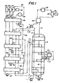
- Figure 1 is a simplified flowsheet of one embodiment of an installation in accordance with the invention, and
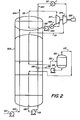
- Figure 2 is a simplified flowsheet of a second embodiment of an installation in accordance with the invention.
- In many parts of the world natural gas is stored in a liquefied state. We have conceived various schemes for recovering power as such liquefied natural gas is evaporated. The schemes herein described appear particularly advantageous both in terms of power recovery and in capital outlay.
- According to the present invention there is provided a method for recovering power from the vaporization of liquefied natural gas, which method comprises the steps of at least partially liquefying a multicomponent stream with said natural gas, pumping said at least partially liquefied multicomponent stream to an elevated pressure, warming said multicomponent stream by cooling and at least partially liquefying a single component stream, heating said.multicomponent stream, expanding said heated multicomponent stream through an expander, recovering power from said expander, recycling said expanded multicomponent stream to be at least partially liquefied, pumping said at least partially liquefied single component stream to an elevated pressure, warming and vaporizing said single component stream, expanding said single component stream through an expander, recovering power from said expander, and recycling said expanded single component stream to be at least partially liquefied by said natural gas and multicomponent stream.
- Preferably, at least part of said natural gas is used to assist in cooling said single component stream.
- Advantageously, said single component is expanded, condensed and pumped in a plurality of stages.
- Typically, the multicomponent stream is heated to a temperature in the range of 40°F (5°C) to 700°F (371°C).
- The present invention also provides an installation for recovering power from the vaporization of liquefied natural gas, which installation comprises a main heat exchanger in which said liquefied natural gas can be warmed by cooling and at least partially liquefying a multicomponent stream, a pump for pressurizing said at least partially liquefied multicomponent stream, at least one heat exchanger in which said liquefied multicomponent stream can be warmed by cooling and at least partially liquefying a single component stream, means for heating said multicomponent stream, an expander for expanding said heated multicomponent stream, a conduit for recycling said multicomponent stream from said expander to said main heat exchanger, a pump for pressurizing said at least partially liquefied single component stream, means for heating said single component stream to produce a vapor, an expander through which said vapor can be expanded, a conduit for recycling said expanded single component to said heat exchanger, and means for recovering power from said expanders.
- Advantageously the installation also includes a conduit for conveying at least part of said natural gas to said heat exchanger to assist in cooling said single component stream.
- The single component can be, for example, propane, propylene, butane or a fluorocarbon, such as sold by the DuPont Company under the Trademark FREON.
- The multicomponent stream could comprise, for example, 2 halofluorocarbons, 2 hydrocarbons and nitrogen or 3 hydrocarbons with or without nitrogen. One preferred multicomponent stream comprises methane, ethane and propane. Another comprises methane, ethylene and propane. Other suitable hydrocarbons include propylene, butane and butylene. Particularly preferred is a mixture of methane, ethane, propane and nitrogen.
- Referring to Figure 1 of the drawing, 55265 lb. moles/hr liquefied natural gas is pumped to 1103 psia (76 bars A) by pump 1, which it leaves through conduit 2 at -254°F (-159°C). The liquefied natural gas, which has a composition of (mole %):

- Approximately 73% of the natural gas is withdrawn from the coil wound heat exchanger 3 through conduit 4 at -62°F (-52°C) as liquid. The balance of the natural gas passes through the remainder of the coil wound heat exchanger 3 which it leaves through conduit 5 as vapor at 45°F (7°C).
- The liquefied natural gas passing through conduit 4 is progressively heated in
heat exchangers 6, 7, 8 and 9 and leaves heat exchanger 9 as vapor at 45°F (7°C) through conduit 10. It then joins the remaining vapor in conduit 5. - 37,956 lb. moles/hr of a gaseous multicomponent stream comprising (mole %):

phase separator 13. Liquid from the phase separator (17,430 lb. moles/hr) is pumped to 760 psia (52.4 bars A) by pump 14 and is introduced intoconduit 15 via conduit 16. Vapor from the phase separator is returned to the coil wound heat exchanger 3 via conduit 17 and is totally liquefied when it leaves the coil wound heat exchanger 3 throughconduit 18. It is then pumped to 790 psia (54.5 bars A) by pump 19 which it leaves throughconduit 15. The liquid is progressively warmed as it passes through the coil wound heat exchanger 3 which it leaves throughconduit 20 at -62°F (-52°C) and 730 psia (50.4 bars A) as a totally liquid stream. - The liquid in
conduit 20 is progressively warmed inheat exchangers 6, 7, 8 and 9 and leaves heat exchanger 9 at 13.3°F (-8.7°C) as a two phase mixture containing approximately equimolar quantities of liquid and vapor. Almost all the remaining liquid is vaporized inheat exchanger 21 which is warmed by sea water and from which the multicomponent stream emerges at 45°F (7.2°C). The multicomponent stream is then heated to 396°F (202°C) inheat exchanger 22 and to 650°F (343°C) inheater 23 which is fired by natural gas. The multicomponentstream leaving heater 23 is then expanded from 690 psia (47.6 bars A) to 91 psia (6.3 bars A) across expander 24 which is coupled to agenerator 25. The multicomponent stream leaves the expander 24 at 456°F (235°C) and is further cooled to 50°F (10°C) inheat exchanger 22 which it leaves at 85 psia (5.9 bars A) via conduit 11. - Turning now to the top left of Figure 1, 24,972 lb. moles/hr propane at 75 psia (5 bars A) and 650°F (343°C) are passed through
conduit 26 to a three stage expander having a first stage 27, a second stage 28 and a third stage 29 each of which is coupled to agenerator 30. - The propane is expanded to 55 psia (3.8 bars A) in the first stage 27 and is then divided between two conduits 31 and 32. Approximately 26% of the propane passes through conduit 31 while the balance passes through conduit 32 to second stage 28 where it is expanded to 33 psia (2.3 bars A). The propane leaves the second stage 28 at 603°F (317°C) and is divided between two conduits 33 and 34. Approximately 22% of the propane passes through conduit 33 while the balance passes through conduit 34 to third stage 29 where it is expanded to 20 psia (1.4 bars A) before leaving through conduit 35.
- The propane in conduit 35 is passed through
heat exchangers 36, 9, 8, 7 and 6, wherein it is progressively cooled and liquefied. It is then pumped to 30 psia (2.1 bars A) bypump 37 which it leaves throughconduit 38 en route to conduit 33 viajunction 39. - The propane in conduit 33 is passed through heat exchangers 36, 9, and 8 wherein it is progressively cooled and partially liquefied. It is then joined by liquid.propane at
junction 39 and the combined stream is passed through heat exchanger 7 where the remaining gaseous propane is liquefied. The liquid propane is then pumped to 52 psia (3.6 bars A) bypump 40 and is passed through conduit 41 at -l2°F (-24°C) to junction 42. - Propane from conduit 31 is passed through heat exchangers 36 and 9 wherein it is cooled. It is then joined by liquid propane at junction 42 and the combined stream is totally liquefied in heat exchanger 8. The liquid is then pumped to 90 psia (6.2 bars A) by
pump 43 which it leaves throughconduit 44. The liquid propane is then totally vaporized against sea water inheat exchanger 45 which the gaseous propane leaves at 45°F (7.2°C). It is then heated to 596°F (313°C) in heat exchanger 36 and is further heated to 650°F (343°C) in heater 46 which it leaves at 75 psia (5 bars A). - Various modifications to the installation described with reference to the drawings can be made. For example, whereas the propane expander has three stages of expansion it could have more or less stages with a corresponding change in the number of pumps and the number of heat exchangers. In general, the higher the number of stages the better the power recovery at
generator 30 but the higher the capital cost. The arrangement shown represents a reasonable compromise between capital cost and power recovery. Alternatively, stream 11 may be subjected to a plurality of condensations followed by phase separation, such as illustrated byseparator 13, as the stream 11 passes from the warm to the cold end of heat exchanger 3. Each additional stage would require its own pump and again a balance must be found between efficiency and capital cost. Stream 11 may be completely condensed in heat exchanger 3 without intermediate separation. Complete elimination of the separator would require alteration of the composition of the multicomponent stream to a less optimum composition with less power recovering efficiency. - The propane used in
conduit 26 may be replaced by propylene, butane and the flourocarbon refrigerants such as those sold by the DuPont Company under the FREON trademark. - Similarly, the multicomponent refrigerant could conceivably comprise, for example, 2 halofluorocarbons, 2'hydrocarbons and nitrogen or 3 or more hydrocarbons with or without nitrogen.
- In the installation described in Figure 1 the generators produced a total 43800 kW of energy.
- Referring now to Figure 2, 34,410 lb. moles/hr liquefied natural gas is pumped to 1347 psia (92.9 bars A) by pump 101 which it leaves through conduit 102 at - 246°F (-159°C). The liquefied natural gap which has a composition of (mole %):
- N 2 0.05
- CH 4 96.96
- C2H6 1.61
- C3H8 0.7
- C 4 + 0.68 is gradually warmed in coil
wound heat exchanger 103 which it leaves through conduit 104 at -28.7°F (-34°C) as vapor. - 32,077 lb. moles/hr of a gaseous multicomponent stream comprising (mole %):
- N 2 - 0.9 CH4 43.4
- C2H6 47.5
- C3H8 8.2 is introduced into coil
wound heat exchanger 103 through conduit 111. As it passes through the coil woundheat exchanger 103 it is progressively cooled and partially liquefied. The two phase mixture thus formed is withdrawn from the coil wound heat exchanger 3 through conduit 112 at -186°F (-121°C) and is introduced intophase separator 113. Liquid from the phase separator (28709 lb. moles/hr) is pumped to 310 psia (21.4 bars A) bypump 114 and is introduced intoconduit 115 viaconduit 116. Vapor from thephase separator 113 is returned to the coil woundheat exchanger 103 via conduit 117 and is totally liquefied when it leaves the coil woundheat exchanger 103 through conduit 118. It is then pumped to 340 psia (23.5 bars A) by pump 119 which it leaves throughconduit 115. The liquid is progressively warmed as it passes through the coil woundheat exchanger 103. It joins with liquid fromconduit 116 and the combined stream leaves coil woundheat exchanger 103 throughconduit 120 at -29°F (-34°C) as a two phase mixture containing approximately 25% (by moles) liquid. The remaining liquid is totally vaporized and the gas heated to 50°F (10°C) by indirect heat exchange with sea water inheat exchanger 121. The heated gas is then expanded to 89 psia (6.1 bars A) throughexpander 124 and leaves at -28°F (-33°C) through conduit lll. - Turning now to the propane cycle, 11,165 lb. moles/hr gaseous propane at 25 psia (1.7 bars A) and - 9°F (-23°C) enters
main heat exchanger 103 viaconduit 131. The propane is totally liquefied and leaves themain heat exchanger 103 throughconduit 132 as liquid at -22°F (-30°C). It is then pumped to 89 psia (6.1 bars A) bypump 143 before being vaporized by indirect heat exchange with sea water inheat exchanger 145.' The resulting vapor at 50°F (10°C) is expanded throughexpander 127 and the expanded gas is recycled throughconduit 131 as shown. - In the installation in Figure 2 the
generator 125 driven byexpanders
Claims (11)
Applications Claiming Priority (2)
| Application Number | Priority Date | Filing Date | Title |
|---|---|---|---|
| US241184 | 1981-03-06 | ||
| US06/241,184 US4479350A (en) | 1981-03-06 | 1981-03-06 | Recovery of power from vaporization of liquefied natural gas |
Publications (3)
| Publication Number | Publication Date |
|---|---|
| EP0059955A2 true EP0059955A2 (en) | 1982-09-15 |
| EP0059955A3 EP0059955A3 (en) | 1983-01-05 |
| EP0059955B1 EP0059955B1 (en) | 1987-11-11 |
Family
ID=22909608
Family Applications (1)
| Application Number | Title | Priority Date | Filing Date |
|---|---|---|---|
| EP82101744A Expired EP0059955B1 (en) | 1981-03-06 | 1982-03-05 | Recovery of power from vaporization of liquefied natural gas |
Country Status (9)
| Country | Link |
|---|---|
| US (1) | US4479350A (en) |
| EP (1) | EP0059955B1 (en) |
| JP (1) | JPS57165611A (en) |
| KR (1) | KR880002381B1 (en) |
| BR (1) | BR8201183A (en) |
| CA (1) | CA1169667A (en) |
| DE (1) | DE3277635D1 (en) |
| ES (1) | ES8306851A1 (en) |
| GR (1) | GR75882B (en) |
Cited By (2)
| Publication number | Priority date | Publication date | Assignee | Title |
|---|---|---|---|---|
| EP0470532A1 (en) * | 1990-08-07 | 1992-02-12 | Linde Aktiengesellschaft | Process for gasifying liquid natural gas |
| CN104390125A (en) * | 2014-10-27 | 2015-03-04 | 中国海洋石油总公司 | Method and device applied to constant-pressure recovery of liquefied natural gas flash steam |
Families Citing this family (17)
| Publication number | Priority date | Publication date | Assignee | Title |
|---|---|---|---|---|
| TW432192B (en) * | 1998-03-27 | 2001-05-01 | Exxon Production Research Co | Producing power from pressurized liquefied natural gas |
| TW414851B (en) * | 1998-03-27 | 2000-12-11 | Exxon Production Research Co | Producing power from liquefied natural gas |
| US6052997A (en) * | 1998-09-03 | 2000-04-25 | Rosenblatt; Joel H. | Reheat cycle for a sub-ambient turbine system |
| US7608935B2 (en) * | 2003-10-22 | 2009-10-27 | Scherzer Paul L | Method and system for generating electricity utilizing naturally occurring gas |
| US7607310B2 (en) | 2004-08-26 | 2009-10-27 | Seaone Maritime Corp. | Storage of natural gas in liquid solvents and methods to absorb and segregate natural gas into and out of liquid solvents |
| EP1789739B1 (en) * | 2004-09-14 | 2020-03-04 | Exxonmobil Upstream Research Company | Method of extracting ethane from liquefied natural gas |
| US7299643B2 (en) * | 2004-09-29 | 2007-11-27 | Chevron U.S.A. Inc. | Method for recovering LPG boil off gas using LNG as a heat transfer medium |
| ES2793304T3 (en) | 2005-07-08 | 2020-11-13 | Seaone Holdings Llc | Method of transporting and storing bulk gas in a liquid medium |
| US10780955B2 (en) | 2008-06-20 | 2020-09-22 | Seaone Holdings, Llc | Comprehensive system for the storage and transportation of natural gas in a light hydrocarbon liquid medium |
| US8132411B2 (en) * | 2008-11-06 | 2012-03-13 | Air Products And Chemicals, Inc. | Rankine cycle for LNG vaporization/power generation process |
| WO2014141719A1 (en) * | 2013-03-15 | 2014-09-18 | メタウォーター株式会社 | Binary power generating system |
| JP6057219B2 (en) * | 2014-02-17 | 2017-01-11 | メタウォーター株式会社 | Binary power generation system |
| JP5531250B1 (en) * | 2013-03-15 | 2014-06-25 | メタウォーター株式会社 | Binary power generation system |
| US10655913B2 (en) * | 2016-09-12 | 2020-05-19 | Stanislav Sinatov | Method for energy storage with co-production of peaking power and liquefied natural gas |
| US10731795B2 (en) * | 2017-08-28 | 2020-08-04 | Stanislav Sinatov | Method for liquid air and gas energy storage |
| FR3140650A1 (en) * | 2022-10-05 | 2024-04-12 | L'air Liquide, Societe Anonyme Pour L'etude Et L'exploitation Des Procedes Georges Claude | Device and process for vaporization or pseudo-vaporization of liquid hydrogen and production of electrical energy |
| US11780312B1 (en) * | 2022-12-23 | 2023-10-10 | Jay Stephen Kaufman | Exhaust gas heat recovery from cryo-compression engines with cogeneration of cryo-working fluid |
Citations (5)
| Publication number | Priority date | Publication date | Assignee | Title |
|---|---|---|---|---|
| US3479832A (en) * | 1967-11-17 | 1969-11-25 | Exxon Research Engineering Co | Process for vaporizing liquefied natural gas |
| DE1922779A1 (en) * | 1968-05-10 | 1970-06-25 | Linde Ag | Evaporating natural gas - by combining evaporator with condensation turbine of power station |
| SU431371A1 (en) * | 1970-12-29 | 1974-06-05 | ||
| EP0009387A1 (en) * | 1978-09-18 | 1980-04-02 | Fluor Corporation | Process for obtaining energy during the regasification of liquefied gases |
| FR2496754A1 (en) * | 1980-12-22 | 1982-06-25 | Chiyoda Chem Eng Construct Co | Energy recovery from natural gas by rankine cycle - uses liquefied natural gas for low temperature in first cycle to drive turbine for second |
Family Cites Families (11)
| Publication number | Priority date | Publication date | Assignee | Title |
|---|---|---|---|---|
| GB465802A (en) * | 1935-07-04 | 1937-05-13 | Pierre Zehnle | Improvements relating to heating plant and to the use of heavy hydrocarbon or fluorcarbon vapours, such as butane |
| NL112932C (en) * | 1958-06-11 | |||
| US3068659A (en) * | 1960-08-25 | 1962-12-18 | Conch Int Methane Ltd | Heating cold fluids with production of energy |
| GB933584A (en) * | 1962-05-02 | 1963-08-08 | Conch Int Methane Ltd | A method of gasifying a liquefied gas while producing mechanical energy |
| GB1031616A (en) * | 1964-05-20 | 1966-06-02 | Internat Res And Dev Company L | Improvements in and relating to closed cycle gas turbine plants |
| FR2187702B1 (en) * | 1972-06-13 | 1976-11-12 | Nuovo Pignone Spa | |
| DE2407617A1 (en) * | 1974-02-16 | 1975-08-21 | Linde Ag | METHOD OF ENERGY RECOVERY FROM LIQUID GASES |
| JPS5491648A (en) * | 1977-12-29 | 1979-07-20 | Toyokichi Nozawa | Lnggfleon generation system |
| JPS55123306A (en) * | 1979-03-14 | 1980-09-22 | Chiyoda Chem Eng & Constr Co Ltd | Vaporization of liquefied natural gas and its energy recovering method |
| JPS5925851B2 (en) * | 1979-06-22 | 1984-06-21 | 千代田化工建設株式会社 | Power recovery method using liquefied natural gas vaporization and cold heat using the cascade Rankine cycle |
| US4372124A (en) * | 1981-03-06 | 1983-02-08 | Air Products And Chemicals, Inc. | Recovery of power from the vaporization of natural gas |
-
1981
- 1981-03-06 US US06/241,184 patent/US4479350A/en not_active Expired - Lifetime
-
1982
- 1982-03-02 CA CA000397439A patent/CA1169667A/en not_active Expired
- 1982-03-04 ES ES510142A patent/ES8306851A1/en not_active Expired
- 1982-03-05 EP EP82101744A patent/EP0059955B1/en not_active Expired
- 1982-03-05 GR GR67501A patent/GR75882B/el unknown
- 1982-03-05 DE DE8282101744T patent/DE3277635D1/en not_active Expired
- 1982-03-05 BR BR8201183A patent/BR8201183A/en unknown
- 1982-03-05 JP JP57034102A patent/JPS57165611A/en active Pending
- 1982-03-06 KR KR8200978A patent/KR880002381B1/en active
Patent Citations (5)
| Publication number | Priority date | Publication date | Assignee | Title |
|---|---|---|---|---|
| US3479832A (en) * | 1967-11-17 | 1969-11-25 | Exxon Research Engineering Co | Process for vaporizing liquefied natural gas |
| DE1922779A1 (en) * | 1968-05-10 | 1970-06-25 | Linde Ag | Evaporating natural gas - by combining evaporator with condensation turbine of power station |
| SU431371A1 (en) * | 1970-12-29 | 1974-06-05 | ||
| EP0009387A1 (en) * | 1978-09-18 | 1980-04-02 | Fluor Corporation | Process for obtaining energy during the regasification of liquefied gases |
| FR2496754A1 (en) * | 1980-12-22 | 1982-06-25 | Chiyoda Chem Eng Construct Co | Energy recovery from natural gas by rankine cycle - uses liquefied natural gas for low temperature in first cycle to drive turbine for second |
Non-Patent Citations (1)
| Title |
|---|
| CHEMICAL ABSTRACTS, vol. 82, no. 8, February 24, 1975, page 189, abstract no.46209w, Columbus, Ohio, US; & SU-A-431 371 (A.I. KALINA ET AL.) 05-06-1974 * |
Cited By (2)
| Publication number | Priority date | Publication date | Assignee | Title |
|---|---|---|---|---|
| EP0470532A1 (en) * | 1990-08-07 | 1992-02-12 | Linde Aktiengesellschaft | Process for gasifying liquid natural gas |
| CN104390125A (en) * | 2014-10-27 | 2015-03-04 | 中国海洋石油总公司 | Method and device applied to constant-pressure recovery of liquefied natural gas flash steam |
Also Published As
| Publication number | Publication date |
|---|---|
| GR75882B (en) | 1984-08-02 |
| EP0059955B1 (en) | 1987-11-11 |
| JPS57165611A (en) | 1982-10-12 |
| BR8201183A (en) | 1983-01-18 |
| KR830009355A (en) | 1983-12-19 |
| ES510142A0 (en) | 1983-06-01 |
| KR880002381B1 (en) | 1988-11-03 |
| EP0059955A3 (en) | 1983-01-05 |
| US4479350A (en) | 1984-10-30 |
| CA1169667A (en) | 1984-06-26 |
| ES8306851A1 (en) | 1983-06-01 |
| DE3277635D1 (en) | 1987-12-17 |
Similar Documents
| Publication | Publication Date | Title |
|---|---|---|
| US4479350A (en) | Recovery of power from vaporization of liquefied natural gas | |
| US4437312A (en) | Recovery of power from vaporization of liquefied natural gas | |
| KR101659224B1 (en) | Integrated nitrogen removal in the production of liquefied natural gas using refrigerated heat pump | |
| JP2675715B2 (en) | Liquefaction process of nitrogen stream produced by cryogenic air separation unit | |
| EP1634015B1 (en) | Power cycle with liquefied natural gas regasification | |
| US4970867A (en) | Liquefaction of natural gas using process-loaded expanders | |
| US8132411B2 (en) | Rankine cycle for LNG vaporization/power generation process | |
| KR101680465B1 (en) | Integrated nitrogen removal in the production of liquefied natural gas using dedicated reinjection circuit | |
| CA2291415C (en) | Dual mixed refrigerant cycle for gas liquefaction | |
| US5157925A (en) | Light end enhanced refrigeration loop | |
| EP0059954B1 (en) | Recovery of power from the vaporization of natural gas | |
| US6449982B1 (en) | Process for partial liquefaction of a fluid containing hydrocarbons, such as natural gas | |
| NO803742L (en) | PROCEDURE AND SYSTEM FOR COOLING A FLUIDUM TO BE COOLED TO A LOW TEMPERATURE | |
| EP0043212B1 (en) | Producing power from a cryogenic liquid | |
| KR20150123191A (en) | Integrated nitrogen removal in the production of liquefied natural gas using intermediate feed gas separation | |
| US11821682B2 (en) | Natural gas processing using supercritical fluid power cycles | |
| EP3561421B1 (en) | Improved method and system for cooling a hydrocarbon stream using a gas phase refrigerant | |
| KR20220047785A (en) | Methods for recovering refrigeration energy through liquefaction or power generation of gas streams | |
| US20220170695A1 (en) | Method and system for condensing a gas | |
| CN117091352A (en) | For cooling rich CO 2 Method and apparatus for streaming |
Legal Events
| Date | Code | Title | Description |
|---|---|---|---|
| PUAI | Public reference made under article 153(3) epc to a published international application that has entered the european phase |
Free format text: ORIGINAL CODE: 0009012 |
|
| AK | Designated contracting states |
Designated state(s): BE DE FR GB IT NL |
|
| PUAL | Search report despatched |
Free format text: ORIGINAL CODE: 0009013 |
|
| AK | Designated contracting states |
Designated state(s): BE DE FR GB IT NL |
|
| 17P | Request for examination filed |
Effective date: 19830302 |
|
| RBV | Designated contracting states (corrected) |
Designated state(s): BE DE FR GB IT NL |
|
| ITF | It: translation for a ep patent filed |
Owner name: DE DOMINICIS & MAYER S.R.L. |
|
| GRAA | (expected) grant |
Free format text: ORIGINAL CODE: 0009210 |
|
| AK | Designated contracting states |
Kind code of ref document: B1 Designated state(s): BE DE FR GB IT NL |
|
| REF | Corresponds to: |
Ref document number: 3277635 Country of ref document: DE Date of ref document: 19871217 |
|
| ET | Fr: translation filed | ||
| PLBE | No opposition filed within time limit |
Free format text: ORIGINAL CODE: 0009261 |
|
| STAA | Information on the status of an ep patent application or granted ep patent |
Free format text: STATUS: NO OPPOSITION FILED WITHIN TIME LIMIT |
|
| 26N | No opposition filed | ||
| PGFP | Annual fee paid to national office [announced via postgrant information from national office to epo] |
Ref country code: GB Payment date: 19930208 Year of fee payment: 12 |
|
| PGFP | Annual fee paid to national office [announced via postgrant information from national office to epo] |
Ref country code: DE Payment date: 19930329 Year of fee payment: 12 |
|
| ITTA | It: last paid annual fee | ||
| PG25 | Lapsed in a contracting state [announced via postgrant information from national office to epo] |
Ref country code: GB Effective date: 19940305 |
|
| GBPC | Gb: european patent ceased through non-payment of renewal fee |
Effective date: 19940305 |
|
| PG25 | Lapsed in a contracting state [announced via postgrant information from national office to epo] |
Ref country code: DE Effective date: 19941201 |
|
| PGFP | Annual fee paid to national office [announced via postgrant information from national office to epo] |
Ref country code: NL Payment date: 19970120 Year of fee payment: 16 |
|
| PGFP | Annual fee paid to national office [announced via postgrant information from national office to epo] |
Ref country code: FR Payment date: 19970307 Year of fee payment: 16 |
|
| PGFP | Annual fee paid to national office [announced via postgrant information from national office to epo] |
Ref country code: BE Payment date: 19970402 Year of fee payment: 16 |
|
| PG25 | Lapsed in a contracting state [announced via postgrant information from national office to epo] |
Ref country code: FR Free format text: THE PATENT HAS BEEN ANNULLED BY A DECISION OF A NATIONAL AUTHORITY Effective date: 19980331 Ref country code: BE Free format text: LAPSE BECAUSE OF NON-PAYMENT OF DUE FEES Effective date: 19980331 |
|
| BERE | Be: lapsed |
Owner name: AIR PRODUCTS AND CHEMICALS INC. Effective date: 19980331 |
|
| PG25 | Lapsed in a contracting state [announced via postgrant information from national office to epo] |
Ref country code: NL Free format text: LAPSE BECAUSE OF NON-PAYMENT OF DUE FEES Effective date: 19981001 |
|
| NLV4 | Nl: lapsed or anulled due to non-payment of the annual fee |
Effective date: 19981001 |
|
| REG | Reference to a national code |
Ref country code: FR Ref legal event code: ST |