EP0059699A2 - Rettungseinrichtung - Google Patents
Rettungseinrichtung Download PDFInfo
- Publication number
- EP0059699A2 EP0059699A2 EP82850036A EP82850036A EP0059699A2 EP 0059699 A2 EP0059699 A2 EP 0059699A2 EP 82850036 A EP82850036 A EP 82850036A EP 82850036 A EP82850036 A EP 82850036A EP 0059699 A2 EP0059699 A2 EP 0059699A2
- Authority
- EP
- European Patent Office
- Prior art keywords
- band
- braking
- person
- along
- regulator
- Prior art date
- Legal status (The legal status is an assumption and is not a legal conclusion. Google has not performed a legal analysis and makes no representation as to the accuracy of the status listed.)
- Withdrawn
Links
Images


Classifications
-
- A—HUMAN NECESSITIES
- A62—LIFE-SAVING; FIRE-FIGHTING
- A62B—DEVICES, APPARATUS OR METHODS FOR LIFE-SAVING
- A62B1/00—Devices for lowering persons from buildings or the like
- A62B1/06—Devices for lowering persons from buildings or the like by making use of rope-lowering devices
- A62B1/14—Devices for lowering persons from buildings or the like by making use of rope-lowering devices with brakes sliding on the rope
Definitions
- the present invention relates to a device for use in appliances for the rescue of persons from highly situated places, comprising a drum provided at the place of stay of the person in question for storing an elongated flexible carrying means, and a device adapted to be moved under braking along said carrying means and supporting a harness, sack or like means for the person to be rescued.
- the present invention permits persons to escape on their own and without help from other people and to reach the ground uninjured also from heights of two- three hundred meters or more.
- the elongated flexible carrying means is in the form of a band having a thickness that is small in relation to its width, and that the person-carrying device, which is movable under braking along said band, has braking surfaces engageable with the sides of the band.
- the device according to the invention includes a harness with a rescue-sack in which the distressed person rides or slides along a band, preferably consisting of steel and being, say, 50 mm wide and 0.5 mm thick and having rounded side edges.
- the band is stored in a preferably cylindrical cassette in which the band is wound on a rotary cylindrical journal which is borne in the cassette.
- the rescue device is to be used the band is pulled out through an opening in the cassette.
- the size of the cassette is adapted to the required length of the band which must reach down to the ground in unwound condition.
- the cassette is provided with stable anchoring means above or on the side of a suitable opening and is so arranged that the band cannot unwind by itself in rest position.
- the band is sealed to the cassette and consequently the seal must be broken before the device is used.
- a crank means makes it possible to rewind the band into the cassette after use.
- a braking means for instance a simple centrifugal speed regulator, is fitted to the cassette so that the band cannot get entangled during unwinding.
- the band which preferably is of tempered stainless steel, has a strength of 4 - 5000 kg, and is resistant to any temperature that it normally can be exposed to in case of fire without therefore losing carrying capacity to the point where the rescue work would be impaired or rendered impossible.
- An inflatable cushion of about one meter in diameter can be detachably arranged in the outer end of the band. The cushion is preferably attached to the band at its upper centre and is provided with a C0 2 bottle for inflating purposes.
- a handle is fitted on the periphery of the cushion. People on the ground should possibly help each other to keep the band spaced from the wall of the building, thus facilitating the rescue work and reducing the risk of injuries by shocks or scraping against the outer wall of the building. The landing takes place on the cushion which softens the shock.
- the maximum falling velocity for this rescue device is set as low as 1.5 meter per second to permit rescuing persons without experience as well as old people in bad physical condition.
- Well-trained parachutists are able to stand falling velocities of about 6 m per second without injuries.
- the height rescue device functions automatically during the rescueing operation independently of the body weight, and the falling velocity is automatically adjusted to a preset value, which permits rescuing also an unconscious person provided that somebody can get him into the device.
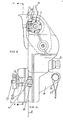
- the appliance comprises, in addition to the band 1, a part II, i.e. the band cassette, attached to the building, and an arbitrary number of rescue devices III which are adapted to be fitted on the band.
- the band I which preferably is made of stainless steel, is of such a length that it will reach from the building part, where the band cassette is attached, and well down to the ground.
- the band is plane and to increase friction it may also be provided with a perforation, a rough surface or otherwise be so treated that the band, together with the details cooperating therewith, will have a satisfactory frictional engagement or a positive tooth-wheel engagement.
- the part II i.e. the band cassette
- the part II i.e. the band cassette
- a housing 101 provided with fittings 102 by means of which the housing can be secured to a suitable building part, e.g. a window frame.
- a band hub 104 containing the required band length, is mounted on a journal 103 in the housing.
- the band hub is provided with a brake 105, preferably a centrifugally regulated brake 106, preventing too rapid unwinding of the band, as this could cause it to get entangled.
- the band drum can be rotated by means of a hand crank (not shown) for use when winding in the band.
- the rescue device proper III is built up of an outer base plate 1, wtth an upper casing 2 and a lower casing 3, and an inner base plate 4 with an inner casing 5.
- the outer base plate and its casings are joined by screw joints and form in joined condition an envelope for all the details included therein which will thus have the desired protection.
- Provided in the upper part of the bottom plate 1 are two bearing sites for ball bearings 10 which support the shaft 9 on which two guide flanges 6 are provided on the friction drum 7 which is supported by the hub 8.
- a gear wheel 11 is attached on the free end of the shaft 9. This gear wheel 11 is in permanent mesh with another gear wheel 12 which is formed in one side of a shaft 13 in the opposite end of which another gear wheel 15 is provided.
- the shaft 13, which supports the gear wheels 12 and 15, is provided in either end with journals carried by the ball bearings 14.
- a centrifugal regulator of per se known design but working according to a new mode of operation.
- This regulator has a regulator shaft 17 supported in two ball bearings 18 which support the regulator driven by the gear wheel 19 which is in permanent engagement with the above-mentioned gear wheel 15.
- the gear wheel In the right-hand part of the regulator shaft 17 the gear wheel is fixedly connected to the shaft.
- the regulator shaft 17 forms spring brackets for the regulator springs 21 with mounting screws 23.
- the right-hand spring bracket forms a stationary unit with the regulator shaft 17.
- a regulator disc is formed with a hub 22 running freely with a key joint against the regulator shaft 17 to prevent rotation or turning of the details 17 and 22.
- the regulator disc 22 1 which on its hub part also has mountings formed for the regulator springs 21, these springs 21 are connected with the screws 23 and on the central part of said regulator springs the regulator weights 20 are fitted.
- the centrifugal force acts upon rotation of the regulator shaft 17 in such a way that the weights, which are thrown outwardly in radial direction, entrain the regulator disc 22 to the right, whereby the fork-shaped regulator lever 24 via the two ball bearings 25 on their journals 26 and lock nuts 27 also is carried to the right while the regulator lever turns about its bearing screw 28.
- the opposite end of the regulator lever 24 is formed, as also appears from section B-B, Fig. 10, with a ball bearing 30 supported by a pin 71 locked for instance by split pins 72.
- the adjusting forces produced by the centrifugal regulator are a function of, on one hand, the regulator revolution and, on the other hand, of the mass of-the regulator weights. To obtain a good function together with a low weight of the components in this case the regulator is geared up to about 5000 r.p.m.
- the straining screw 43 has a conical head anchored in the inner base plate 4, and a tension spring 44 is adjusted by means of an adjusting nut 45 and a locking nut 46 so that a suitable pressure is obtained between the straining roller 39 relative to the friction roller 7 via the conveyor band steel 67.
- a tension spring 44 is adjusted by means of an adjusting nut 45 and a locking nut 46 so that a suitable pressure is obtained between the straining roller 39 relative to the friction roller 7 via the conveyor band steel 67.
- a tension spring 44 is adjusted by means of an adjusting nut 45 and a locking nut 46 so that a suitable pressure is obtained between the straining roller 39 relative to the friction roller 7 via the conveyor band steel 67.
- a tension spring 44 is adjusted by means of an adjusting nut 45 and a locking nut 46 so that a suitable pressure is obtained between the straining roller 39 relative to the friction roller 7 via the conveyor band steel 67.
- lugs 51 between which a non-displaceable but pivotable brake block 48 with brake
- the device is provided with two joints or hinges the appearance of which appears from Figs. 5 and 9, sections F-F and G-G and Fig. 7.
- Fig. 9 the hinge joints are shown from the side.
- the hinge lug 53 forms part of the outer base plate 1.
- the hinge lug 55 is part of the inner casing 5.
- the joint on the pivot pin 54 is displaced downwards in the drawing, i.e. inwards towards the inner casing 5.
- the entire device is suspended in open condition in its suspension lug 70 on the suspension hook 108 intended therefor on the release mechanism of the band cassette.
- the open device is suspended on the outside of the band which is to be visible from the interior of the premises and pass between the guide flanges on the friction roller 6, and in the lower part pass between the guide pins 52.
- pivot pin 60 constitutes a mounting for the pivot sleeve 61 and the straining screw 59 is screwed against a recess in the pivot pin 60 so that this is retained.
- the pivot pin is movable and is pivotally mounted between two lugs 69 which are formed on the outer base plate 1.
- the mounting lugs in their turn are formed in one piece with the casing 5 of the inner base plate.
- a groove 63 which is shown in Fig. 15, from which it also appears how the straining and locking wheels 56 after application are blocked against unvoluntary release of the pivotable straining screws 59 because the neck of the locking wheels 56 goes down into a depression which makes it necessary to thread out the locking wheel somewhat more than the depths of the depression before it is possible to turn out the straining screw.
- the tightening of the straining and locking wheels 56 is so strong that the spring pressure in the tension spring 44 is overcome and the outer base plate 1 is entirely pressed together with the inner base plate 4 without any gap being left between them.
- the band should then pass into the rectangular intake of the device and between the guide flanges 6 on the friction drum 7 and further on between the guide pins 52 and out through the rectangular recess.
- the essential novelty of the invention is that the rescue work takes place via a thin and wide band which can be stored in great lengths in suitable cassettes which are most simple to handle without requiring any experience whatsoever.
- the band possesses high heat resistance, high strength and pliability at the same time as it is well apt to have brake blocks applied to it without its lining being worn to any degree worth mentioning during use because the braking according to this method will all the time take place against a cold band surface.
- the temperature increase which takes place in the band as a consequence of the braking decreases rapidly after the passage of the device which is swept by the air which rapidly cools the thin material.
- the invention includes a speed regulator which automatically controls the falling velocity it is possible also to rescue an injured or unconscious person if only somebody manages to get the rescue apparatus on to the injured or unconscious person.
- Another advantage resides in the fact that the person to be rescued can himself control the falling velocity during the descent by reducing the velocity.wholly,or partly by means of the hand brake.
- the height rescue device should be detached from the steel band to make room for the next person to be rescued along the same conveyor steel band.
- the problem with the detachment can be solved in that the band is allowed to end freely on or close to the ground so that the rescue apparatus will run off the band by itself.
- the device according to the invention may of course be constructed in various ways within the scope of the invention and the various components can be arranged in various ways without departing from the inventive idea.
- the advantage of using band along which the rescue work takes place is that a relatively small cassette will hold hundreds of meters of band which has high temperature resistance and is very apt to having braking devices applied against it.
- the band has the advantage relative to drum or disc brakes that the friction or brake linings during the braking period will all the time work on band surfaces which have not been heated before by the braking operation.
- the band is rapidly cooled because of its large width and surface in combination with its small thickness so that a plurality of persons can simultaneously pass down on the band in perfect safety.
Landscapes
- Health & Medical Sciences (AREA)
- General Health & Medical Sciences (AREA)
- Business, Economics & Management (AREA)
- Emergency Management (AREA)
- Emergency Lowering Means (AREA)
Applications Claiming Priority (2)
| Application Number | Priority Date | Filing Date | Title |
|---|---|---|---|
| SE8101288 | 1981-02-27 | ||
| SE8101288 | 1981-02-27 |
Publications (2)
| Publication Number | Publication Date |
|---|---|
| EP0059699A2 true EP0059699A2 (de) | 1982-09-08 |
| EP0059699A3 EP0059699A3 (de) | 1982-10-27 |
Family
ID=20343240
Family Applications (1)
| Application Number | Title | Priority Date | Filing Date |
|---|---|---|---|
| EP82850036A Withdrawn EP0059699A3 (de) | 1981-02-27 | 1982-02-25 | Rettungseinrichtung |
Country Status (2)
| Country | Link |
|---|---|
| EP (1) | EP0059699A3 (de) |
| JP (1) | JPS581469A (de) |
Cited By (3)
| Publication number | Priority date | Publication date | Assignee | Title |
|---|---|---|---|---|
| US4588046A (en) * | 1984-02-06 | 1986-05-13 | Van Der Neer International B.V. | Device for lowering a load along a line |
| AU569749B2 (en) * | 1983-08-18 | 1988-02-18 | Nuss, P.F. | Personal fire escape device |
| WO1989000063A1 (en) * | 1987-06-29 | 1989-01-12 | Ullapara Holdings Pty. Ltd. | Descent system |
Family Cites Families (8)
| Publication number | Priority date | Publication date | Assignee | Title |
|---|---|---|---|---|
| DE68573C (de) * | H. MAYER in Karlsruhe, Ettlingerstrafse 5 a | Vorrichtung zur Rettung aus Feuersgefahr | ||
| US1340146A (en) * | 1917-09-19 | 1920-05-18 | George A Blake | Portable fire-escape |
| US1372853A (en) * | 1920-05-01 | 1921-03-29 | Wellen Henry | Fire-escape device |
| DE905925C (de) * | 1949-07-18 | 1954-03-08 | Eugene Baur | Automatischer Rettungsapparat |
| GB977384A (en) * | 1960-05-20 | 1964-12-09 | R & P Foster Ltd | Improvements in or relating to rope descent devices |
| US3893541A (en) * | 1974-10-29 | 1975-07-08 | Donald A Servais | Window escapes |
| GB2022408A (en) * | 1979-06-06 | 1979-12-19 | Andrews G T | Apparatus for use in escaping from the upper floors of buildings |
| BE879038A (fr) * | 1979-09-27 | 1980-01-16 | Loi Tonio | Appareil d'evacuation par glissement |
-
1982
- 1982-02-25 EP EP82850036A patent/EP0059699A3/de not_active Withdrawn
- 1982-02-26 JP JP3048882A patent/JPS581469A/ja active Pending
Cited By (4)
| Publication number | Priority date | Publication date | Assignee | Title |
|---|---|---|---|---|
| AU569749B2 (en) * | 1983-08-18 | 1988-02-18 | Nuss, P.F. | Personal fire escape device |
| US4588046A (en) * | 1984-02-06 | 1986-05-13 | Van Der Neer International B.V. | Device for lowering a load along a line |
| AU587567B2 (en) * | 1984-02-06 | 1989-08-24 | Van Der Neer International B.V. | Device for lowering a load along a line |
| WO1989000063A1 (en) * | 1987-06-29 | 1989-01-12 | Ullapara Holdings Pty. Ltd. | Descent system |
Also Published As
| Publication number | Publication date |
|---|---|
| EP0059699A3 (de) | 1982-10-27 |
| JPS581469A (ja) | 1983-01-06 |
Similar Documents
| Publication | Publication Date | Title |
|---|---|---|
| US4493396A (en) | Winch for safely lowering a person at a controlled rate | |
| US4406349A (en) | Escape apparatus | |
| CA1249554A (en) | Controlled descent apparatus | |
| CN102821817B (zh) | 绕绳下降装置 | |
| US4602699A (en) | Fire escape with cable reel brake | |
| US3880255A (en) | Emergency fire escape mechanism | |
| US5586617A (en) | Automatic emergency escape for tall structures | |
| US4487292A (en) | Let down apparatus | |
| US4442918A (en) | Emergency escape device | |
| US20070261921A1 (en) | Portable Apparatus for Controlled Descent | |
| US5535848A (en) | Escape chute | |
| WO1984003635A1 (en) | Fire escape apparatus for use in high-rise buildings and the like | |
| US6672428B2 (en) | Personal descent apparatus | |
| US643286A (en) | Fire-escape device. | |
| EP0059699A2 (de) | Rettungseinrichtung | |
| US4063615A (en) | Escape device | |
| GB2233951A (en) | Roping-down device | |
| US4919231A (en) | Device with a lifeline | |
| CN214550688U (zh) | 一种自救逃生消防卷盘 | |
| US3850262A (en) | Escape machine | |
| US4778030A (en) | Escape line clamp assembly | |
| US6868942B2 (en) | Emergency escape system | |
| US3325147A (en) | Personnel lowering devices | |
| CN213466547U (zh) | 一种高层消防连续缓降逃生装置 | |
| RU2209099C1 (ru) | Устройство для гравитационного спуска людей в экстремальных условиях |
Legal Events
| Date | Code | Title | Description |
|---|---|---|---|
| PUAI | Public reference made under article 153(3) epc to a published international application that has entered the european phase |
Free format text: ORIGINAL CODE: 0009012 |
|
| PUAL | Search report despatched |
Free format text: ORIGINAL CODE: 0009013 |
|
| AK | Designated contracting states |
Designated state(s): CH DE FR GB NL SE |
|
| AK | Designated contracting states |
Designated state(s): CH DE FR GB NL SE |
|
| 17P | Request for examination filed |
Effective date: 19830329 |
|
| STAA | Information on the status of an ep patent application or granted ep patent |
Free format text: STATUS: THE APPLICATION IS DEEMED TO BE WITHDRAWN |
|
| 18D | Application deemed to be withdrawn |
Effective date: 19850829 |
|
| RIN1 | Information on inventor provided before grant (corrected) |
Inventor name: NOBELIUS, GUSTAV |