EP0059657A1 - Servolenkungsventil mit vereinfachter Montage - Google Patents
Servolenkungsventil mit vereinfachter Montage Download PDFInfo
- Publication number
- EP0059657A1 EP0059657A1 EP82400263A EP82400263A EP0059657A1 EP 0059657 A1 EP0059657 A1 EP 0059657A1 EP 82400263 A EP82400263 A EP 82400263A EP 82400263 A EP82400263 A EP 82400263A EP 0059657 A1 EP0059657 A1 EP 0059657A1
- Authority
- EP
- European Patent Office
- Prior art keywords
- external
- seal
- distributor element
- distributor
- housing
- Prior art date
- Legal status (The legal status is an assumption and is not a legal conclusion. Google has not performed a legal analysis and makes no representation as to the accuracy of the status listed.)
- Granted
Links
Images
Classifications
-
- B—PERFORMING OPERATIONS; TRANSPORTING
- B62—LAND VEHICLES FOR TRAVELLING OTHERWISE THAN ON RAILS
- B62D—MOTOR VEHICLES; TRAILERS
- B62D5/00—Power-assisted or power-driven steering
- B62D5/06—Power-assisted or power-driven steering fluid, i.e. using a pressurised fluid for most or all the force required for steering a vehicle
- B62D5/08—Power-assisted or power-driven steering fluid, i.e. using a pressurised fluid for most or all the force required for steering a vehicle characterised by type of steering valve used
- B62D5/083—Rotary valves
-
- B—PERFORMING OPERATIONS; TRANSPORTING
- B62—LAND VEHICLES FOR TRAVELLING OTHERWISE THAN ON RAILS
- B62D—MOTOR VEHICLES; TRAILERS
- B62D5/00—Power-assisted or power-driven steering
- B62D5/06—Power-assisted or power-driven steering fluid, i.e. using a pressurised fluid for most or all the force required for steering a vehicle
- B62D5/20—Power-assisted or power-driven steering fluid, i.e. using a pressurised fluid for most or all the force required for steering a vehicle specially adapted for particular type of steering gear or particular application
- B62D5/22—Power-assisted or power-driven steering fluid, i.e. using a pressurised fluid for most or all the force required for steering a vehicle specially adapted for particular type of steering gear or particular application for rack-and-pinion type
Definitions
- the invention relates to a device forming a power-assisted valve with simplified mounting as well as a particular distribution assembly forming part of such a device.
- the invention relates more particularly to a particular arrangement of the axial sealing system disposed between the aforementioned distribution assembly and the valve housing, considerably facilitating the assembly of these two parts.
- a power steering valve has an independent housing that fits flange onto the steering rack housing of the motor vehicle. It may be desirable, in certain cases, for the valve housing to come integrally with the rack housing. This can indeed result in a reduction in cost and size.
- a power steering valve consists of a number of elements whose assembly must be carried out with precision. This is why, it has long been considered that it was preferable to arrange the valve with an independent box, so as not to complicate the installation of the latter in the steering system of the automobile, in the production line.
- the invention makes it possible in particular to reverse this trend by proposing a sufficiently consistent distribution sub-assembly so that it can be inserted later without difficulty, in a casing formed integrally with the rack housing.
- the invention therefore mainly relates to a device forming a power steering valve, of the type comprising in particular two coaxial distributor elements, respectively an external distributor element and an internal distributor element, the external distributor element being mounted rotating in a bore of a fixed housing and an axial sealing system consisting of a seal and a seal holder fixed to said housing so that said seal is in contact with the external surface of a part of said internal distributor element projecting axially with respect to said external distributor element, characterized in that said seal holder comprises a tubular cylinder part coaxial with said distributor elements, inserted into a portion of corresponding diameter of said bore and fixed to the outer cage of a bearing the inner cage of which is mounted on the external surface of said external distributor element.
- the aforementioned housing is preferably made in one piece with the casing housing the rack with which the power steering valve defined above couples.
- the invention also relates to a distribution assembly for a power steering system, intended to be mounted in a fixed housing and comprising in particular two coaxial distributor elements, respectively an external distributor element and an internal distributor element, a bearing integral with said element .
- an external distributor and an axial sealing system consisting of a seal and a seal holder - intended to be fixed to said housing on the one hand, so that said seal is in contact with the external surface / of said distributor element internal projecting axially with respect to said external distributor element, characterized in that said seal holder comprises a cylindrical tubular part, coaxial with said distributor elements and fixed to the outer cage of said bearing.
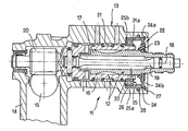
- a device forming a power steering valve 11 is constituted by a distribution assembly 12 inserted in a housing 13 formed integrally with the casing 14 of a rack 15 for steering a motor vehicle.
- the valve arrangement is classic; the distribution assembly 12 mainly comprises two coaxial distributor elements, an external distributor element 16 and an internal distributor element 17. These two distributor elements are mounted rotating relative to each other about their common axis 18 to ensure distribution of fluid to the chambers of an assistance cylinder (not shown).
- the possible angular movement between the distributor elements 16 and 17 is limited to a few degrees and a torsion bar 19 is fixed between the two distributor elements to oppose a restoring torque to any angular offset thereof. , on either side of a neutral position.
- the internal distributor element 17 is intended to be connected to the steering column of the vehicle while the element of external distributor extends inside the casing 14 by a pinion 20, meshing with the rack 15.
- the distributor element 16 is itself mounted rotating in a bore 21 of the housing 13.
- a system axial seal 22 consisting of a seal 23 and a rigid seal holder 24 is fixed to the housing 13 so that said seal 23 is in contact with the external surface of a part of the internal distributor element 17 projecting axially with respect to the external distributor element 16.
- the seal holder 24 comprises a cylindrical tubular part 24a coaxial with the distributor elements 16 and 17 and inserted in a portion 21a, of corresponding diameter of the bore 21.
- the tubular part 24a is fixed to the outer cage 25a of a ball bearing 25 whose inner cage 25b is mounted on the outer surface of the distributor element 16.
- the inner cage 25b is immobilized between a shoulder of the distributor element 16 and a circlip 30 engaged in an annular groove made on the external surface of this same distributor element.
- the innermost axial face of the cage 25a constitutes a stop for positioning the distributor elements relative to the housing 13 since it is in contact with an internal shoulder 26 of the bore 21 of said housing.
- the seal holder 24 is immobilized in the portion 21a of this bore by means of a circlip 27 engaged in an annular groove of this same bore.
- the circlip 27 is in abutment with one end of the cylindrical part 24a of the seal holder.
- This further comprises a portion in the form of a washer 24b extending in a plane perpendicular to the axis 18 and the seal 23 is molded on either side of this washer by means of holes made therein.
- a seal 28 is inserted into an annular groove in the portion 21a of the bore 21. This seal cooperates with the external surface of the cylindrical part 24a of the seal holder.
Landscapes
- Engineering & Computer Science (AREA)
- Chemical & Material Sciences (AREA)
- Combustion & Propulsion (AREA)
- Transportation (AREA)
- Mechanical Engineering (AREA)
- Power Steering Mechanism (AREA)
- Valve Housings (AREA)
Applications Claiming Priority (2)
| Application Number | Priority Date | Filing Date | Title |
|---|---|---|---|
| FR8103518 | 1981-02-23 | ||
| FR8103518A FR2500398B1 (fr) | 1981-02-23 | 1981-02-23 | Dispositif formant valve de servodirection a montage simplifie et ensemble de distribution formant partie d'un tel dispositif |
Publications (2)
| Publication Number | Publication Date |
|---|---|
| EP0059657A1 true EP0059657A1 (de) | 1982-09-08 |
| EP0059657B1 EP0059657B1 (de) | 1985-05-08 |
Family
ID=9255512
Family Applications (1)
| Application Number | Title | Priority Date | Filing Date |
|---|---|---|---|
| EP19820400263 Expired EP0059657B1 (de) | 1981-02-23 | 1982-02-15 | Servolenkungsventil mit vereinfachter Montage |
Country Status (4)
| Country | Link |
|---|---|
| EP (1) | EP0059657B1 (de) |
| JP (1) | JPS57155158A (de) |
| DE (1) | DE3263628D1 (de) |
| FR (1) | FR2500398B1 (de) |
Cited By (5)
| Publication number | Priority date | Publication date | Assignee | Title |
|---|---|---|---|---|
| GB2203203B (en) * | 1987-03-31 | 1991-01-23 | Glyco Antriebstechnik Gmbh | Rotary joint assembly for the transmission of a medium under pressure between a stationary and a rotatable component |
| EP0903280A1 (de) * | 1997-09-23 | 1999-03-24 | Jidosha Kiki Co., Ltd. | Zahnstangenservolenkung |
| EP0905005A1 (de) * | 1997-06-10 | 1999-03-31 | Jidosha Kiki Co., Ltd. | Servolenkung mit Zahnstange |
| EP1055583A1 (de) * | 1997-09-24 | 2000-11-29 | Jidosha Kiki Co., Ltd. | Servoventil für Zahnstangenlenkung |
| US6216813B1 (en) | 1996-05-23 | 2001-04-17 | Bosch Braking Systems Co., Ltd. | Rack-pinion type power steering apparatus |
Citations (3)
| Publication number | Priority date | Publication date | Assignee | Title |
|---|---|---|---|---|
| US3404704A (en) * | 1964-09-18 | 1968-10-08 | Cam Gear Luton Ltd | Power-steering valve |
| FR2403476A1 (fr) * | 1977-09-15 | 1979-04-13 | Bendix Corp | Valve hydraulique de commande, en particulier pour direction assistee |
| FR2421020A1 (fr) * | 1978-03-27 | 1979-10-26 | Trw Inc | Distributeur de direction assistee et son procede de realisation |
-
1981
- 1981-02-23 FR FR8103518A patent/FR2500398B1/fr not_active Expired
-
1982
- 1982-02-15 DE DE8282400263T patent/DE3263628D1/de not_active Expired
- 1982-02-15 EP EP19820400263 patent/EP0059657B1/de not_active Expired
- 1982-02-22 JP JP2616582A patent/JPS57155158A/ja active Pending
Patent Citations (3)
| Publication number | Priority date | Publication date | Assignee | Title |
|---|---|---|---|---|
| US3404704A (en) * | 1964-09-18 | 1968-10-08 | Cam Gear Luton Ltd | Power-steering valve |
| FR2403476A1 (fr) * | 1977-09-15 | 1979-04-13 | Bendix Corp | Valve hydraulique de commande, en particulier pour direction assistee |
| FR2421020A1 (fr) * | 1978-03-27 | 1979-10-26 | Trw Inc | Distributeur de direction assistee et son procede de realisation |
Cited By (6)
| Publication number | Priority date | Publication date | Assignee | Title |
|---|---|---|---|---|
| GB2203203B (en) * | 1987-03-31 | 1991-01-23 | Glyco Antriebstechnik Gmbh | Rotary joint assembly for the transmission of a medium under pressure between a stationary and a rotatable component |
| US6216813B1 (en) | 1996-05-23 | 2001-04-17 | Bosch Braking Systems Co., Ltd. | Rack-pinion type power steering apparatus |
| EP0905005A1 (de) * | 1997-06-10 | 1999-03-31 | Jidosha Kiki Co., Ltd. | Servolenkung mit Zahnstange |
| US6021685A (en) * | 1997-06-10 | 2000-02-08 | Jidosha Kiki Co., Ltd. | Rack-pinion type power steering apparatus |
| EP0903280A1 (de) * | 1997-09-23 | 1999-03-24 | Jidosha Kiki Co., Ltd. | Zahnstangenservolenkung |
| EP1055583A1 (de) * | 1997-09-24 | 2000-11-29 | Jidosha Kiki Co., Ltd. | Servoventil für Zahnstangenlenkung |
Also Published As
| Publication number | Publication date |
|---|---|
| FR2500398B1 (fr) | 1985-07-19 |
| JPS57155158A (en) | 1982-09-25 |
| EP0059657B1 (de) | 1985-05-08 |
| DE3263628D1 (en) | 1985-06-13 |
| FR2500398A1 (fr) | 1982-08-27 |
Similar Documents
| Publication | Publication Date | Title |
|---|---|---|
| EP2751437B1 (de) | Vorrichtung zum verbinden einer lenksäule mit einem lenkgetriebegehäuse | |
| FR2738775A1 (fr) | Moyeu de roue motrice pour vehicule automobile | |
| FR2760496A1 (fr) | Agencement d'un arbre dans un support | |
| FR2625264A1 (fr) | Dispositif de raccordement perfectionne pour l'alimentation d'un injecteur | |
| FR2708060A1 (fr) | Agencement de palier pour un arbre tournant appartenant à un mécanisme d'entraînement d'un essuie-glace. | |
| EP1891305A2 (de) | Vorrichtung zum verbinden einer vakuumpumpe mit einer nockenwelle einschliesslich der mittel zur zufuhr von schmierflüssigkeit | |
| FR2463040A1 (fr) | Direction hydraulique a cremaillere | |
| EP0059657A1 (de) | Servolenkungsventil mit vereinfachter Montage | |
| FR2544816A1 (fr) | Dispositif de transmission de couple, du type coulissant, notamment pour direction de vehicule automobile | |
| FR2670726A1 (fr) | Phare pour vehicule. | |
| FR2823284A1 (fr) | Joint articule destine, notamment, a relier entre elles deux conduites d'ecoulement de fluide liquide ou gazeux | |
| EP0914616B1 (de) | Radnabe mit wälzlager mit einer dichtung mit integriertem kodierer | |
| FR2750180A1 (fr) | Arbre tournant incorporant un dispositif de mesure de couple de torsion | |
| EP1955929A1 (de) | Motoreinheit und Reduziergetriebe | |
| EP1092880A1 (de) | Schraubmechanismusbefestigungsvorrichtung mit Spielausgleichsvorrichtung zwischen zwei Bauteilen | |
| FR2682732A1 (fr) | Differentiel a maintien central des axes porte-satellites. | |
| EP0395460B1 (de) | Schwimmsattel-Scheibenbremse | |
| EP1104736B1 (de) | Vorrichtung zum Verbinden eines Lenkungsritzels mit einem Bügel | |
| EP0727340A1 (de) | Vorrichtung zur Montage eines Kraftfahrzeuglenkrads auf eine Lenksäule | |
| EP0260196A1 (de) | Kupplungseinrichtung zwischen einer Motorenanlage und einer Wagenantriebswelle | |
| EP0546918B1 (de) | Vormontiertes Lager mit Kodierelement und einem zusätzlichen Sensor | |
| FR2673153A1 (fr) | Dispositif de lave-glace, pour mecanismes d'essuie-glace. | |
| FR2690122A1 (fr) | Ensemble de crémaillère de direction assistée pour véhicule automobile. | |
| FR2600134A2 (fr) | Dispositif de reglage de la position angulaire d'un organe comportant un moyeu sur un arbre, notamment d'un volant de direction sur un arbre de direction de vehicule automobile | |
| WO2001025669A1 (fr) | Joint articule destine, notamment, a relier entre elles deux conduites d"ecoulement de fluide liquide ou gazeux |
Legal Events
| Date | Code | Title | Description |
|---|---|---|---|
| PUAI | Public reference made under article 153(3) epc to a published international application that has entered the european phase |
Free format text: ORIGINAL CODE: 0009012 |
|
| 17P | Request for examination filed |
Effective date: 19820310 |
|
| AK | Designated contracting states |
Designated state(s): DE GB |
|
| GRAA | (expected) grant |
Free format text: ORIGINAL CODE: 0009210 |
|
| AK | Designated contracting states |
Designated state(s): DE GB |
|
| REF | Corresponds to: |
Ref document number: 3263628 Country of ref document: DE Date of ref document: 19850613 |
|
| PLBE | No opposition filed within time limit |
Free format text: ORIGINAL CODE: 0009261 |
|
| STAA | Information on the status of an ep patent application or granted ep patent |
Free format text: STATUS: NO OPPOSITION FILED WITHIN TIME LIMIT |
|
| 26N | No opposition filed | ||
| PGFP | Annual fee paid to national office [announced via postgrant information from national office to epo] |
Ref country code: DE Payment date: 19930424 Year of fee payment: 12 |
|
| REG | Reference to a national code |
Ref country code: GB Ref legal event code: 732 |
|
| PGFP | Annual fee paid to national office [announced via postgrant information from national office to epo] |
Ref country code: GB Payment date: 19940208 Year of fee payment: 13 |
|
| PG25 | Lapsed in a contracting state [announced via postgrant information from national office to epo] |
Ref country code: DE Effective date: 19941101 |
|
| PG25 | Lapsed in a contracting state [announced via postgrant information from national office to epo] |
Ref country code: GB Effective date: 19950215 |
|
| GBPC | Gb: european patent ceased through non-payment of renewal fee |
Effective date: 19950215 |