EP0059585B1 - Timing angle and speed measurement of shafts - Google Patents
Timing angle and speed measurement of shafts Download PDFInfo
- Publication number
- EP0059585B1 EP0059585B1 EP82300906A EP82300906A EP0059585B1 EP 0059585 B1 EP0059585 B1 EP 0059585B1 EP 82300906 A EP82300906 A EP 82300906A EP 82300906 A EP82300906 A EP 82300906A EP 0059585 B1 EP0059585 B1 EP 0059585B1
- Authority
- EP
- European Patent Office
- Prior art keywords
- signal
- speed
- engine
- angle
- indicating
- Prior art date
- Legal status (The legal status is an assumption and is not a legal conclusion. Google has not performed a legal analysis and makes no representation as to the accuracy of the status listed.)
- Expired
Links
Images

Classifications
-
- F—MECHANICAL ENGINEERING; LIGHTING; HEATING; WEAPONS; BLASTING
- F02—COMBUSTION ENGINES; HOT-GAS OR COMBUSTION-PRODUCT ENGINE PLANTS
- F02D—CONTROLLING COMBUSTION ENGINES
- F02D41/00—Electrical control of supply of combustible mixture or its constituents
- F02D41/0097—Electrical control of supply of combustible mixture or its constituents using means for generating speed signals
-
- G—PHYSICS
- G01—MEASURING; TESTING
- G01P—MEASURING LINEAR OR ANGULAR SPEED, ACCELERATION, DECELERATION, OR SHOCK; INDICATING PRESENCE, ABSENCE, OR DIRECTION, OF MOVEMENT
- G01P3/00—Measuring linear or angular speed; Measuring differences of linear or angular speeds
- G01P3/42—Devices characterised by the use of electric or magnetic means
- G01P3/44—Devices characterised by the use of electric or magnetic means for measuring angular speed
- G01P3/48—Devices characterised by the use of electric or magnetic means for measuring angular speed by measuring frequency of generated current or voltage
- G01P3/481—Devices characterised by the use of electric or magnetic means for measuring angular speed by measuring frequency of generated current or voltage of pulse signals
- G01P3/489—Digital circuits therefor
-
- G—PHYSICS
- G01—MEASURING; TESTING
- G01P—MEASURING LINEAR OR ANGULAR SPEED, ACCELERATION, DECELERATION, OR SHOCK; INDICATING PRESENCE, ABSENCE, OR DIRECTION, OF MOVEMENT
- G01P3/00—Measuring linear or angular speed; Measuring differences of linear or angular speeds
- G01P3/42—Devices characterised by the use of electric or magnetic means
- G01P3/56—Devices characterised by the use of electric or magnetic means for comparing two speeds
Definitions
- This invention relates to apparatus for determining the actual speed of a rotating shaft and the relative angular relationship between that shaft and a further shaft driving or driven by it.
- the invention has particular application in the field of internal combustion engines.
- Basic control of the operation of an internal combustion engine is accomplished by varying the amount of fuel delivered to the engine cylinder by the fuel pump and by controlling the time that the fuel in the cylinder ignites as the pistons approach top dead centre on the compression stroke.
- the amount of fuel delivered to the cylinders will control the speed of the engine while the timing of ignition will control the efficiency of fuel combustion.
- timing shaft is gear driven by the engine crankshaft at half engine speed, with the timing shaft being coupled to the drive shaft of a fuel pump by a timing mechanism so that the fuel pump will deliver fuel to half of the engine cylinders during one engine revolution and to the other half of the cylinders during the next revolution.
- a controllable fuel rack will vary the amount of fuel that the fuel pump delivers to the engine cylinders and a timing mechanism can be used to vary the angular relation between the timing shaft and the fuel pump drive shaft so that fuel is injected into the cylinders at the proper time in engine operation relative to the pistons reaching top dead centre on their compression strokes.
- the system must have a rapid response time, with speed and timing advance angle information being updated many successive times during a single revolution of the engine.
- the apparatus should have a life which meets or exceeds engine overhaul time to prevent premature failutre and loss of control.
- the components utilized for detection of speed and angular displacement of the fuel camshaft need to be simple, rugged and non-contacting.
- Measurements of the timing advance angle have been made by a first sensor operable to detect movement of a fixed point on the timing shaft and a second sensor operable to detect movement of a fixed point on the fuel pump drive shaft, and by means to measure the time between actuation of the two sensors.
- the time lapse is related to the phase angle between the shafts produced by the timing mechanism and can thus be used to provide information as to the mag - nitude of the timing advance angle.
- such systems as have been devised heretofore require careful initial mechanical adjustment of the sensor systems in order to provide accurate timing advance angle information. Accordingly it is desirable to provide a similar sensor system for timing advance angle determination which does not require such initial adjustment.
- Speed and timing advance angle determination systems which provide analog information are inherently inaccurate, since age and varying temperature conditions will often cause component values to change. Thus it is desirable for the system to operate on digital information.
- GB-A-1439553 from which the preamble of present Claim 1 has been derived discloses an apparatus and method for measuring the relative phase shift between two pulse trains of the same variable frequency 1/T, wherein counting the number of pulses occurring during a certain time interval in one of the pulse trains takes place, and wherein the time t between a pulse in one train and a subsequently occurring pulse in the second train is registered by pulses of known frequency proportional in number to this time.
- the relative phase shift is ts ⁇ .
- US-A-4179922 discloses apparatus wherein a succession of electrical pulses are provided, corresponding to successive crankshaft positions, circuitry being provided for responding to the pulses for the purpose of measuring the time interval between successive pulses.
- a system having first and second rotatable shafts and timing means rotatably linking one of the shafts to the other and for varying, within a predetermined range the angular relationship between the shafts comprises:
- the number of first and second members is such that N number of each of the first and second signals are generated during one full revolution of one of the first and second shafts, N being an integer
- the counting means is arranged to obtain N/M number of successive first and second counts during one full revolution, M being an integer
- the angle-indicating means generates N/M number of successive angle-indicating signals during one full revolution, and characterised by angle-averaging means for generating an average-angle signal equal to the sum of NP/M number of successive angle-indicating signals divided by the number NP/M, wherein P is an integer representing a predetermined number of successive full revolutions.
- the sinusoidal torsional effects may be averaged out by obtaining many successive angle-indicating and/or speed-indicating signals during a full revolution of the shafts, and each time new signals are obtained, a predetermined number of successive signals are added together and divided by the predetermined number.
- the first count may be obtained by counting the number of clock pulses occurring between the signal from one of the signal generators and the next signal from the other of the signal generators, by counting the number of clock pulses occurring between the next signal from the other of the signal generators and the next signal from the one of the signal generators, and by adding these two numbers of clock pulses together.
- An initial angle-indicating signal may be obtained corresponding to a minimum advance angle and may be compared to subsequently obtained angle-indicating signals to derive a signal corresponding to the actual angle advance from minimum advance.
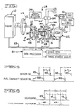
- Fig. 1 illustrates schematically an internal combustion engine 10, such as a four-stroke-cycle diesel engine, the engine having a crank shaft 11 to which circular flywheel member 12 is fixed for rotation at a speed equal to the engine speed.
- Meshed gears 13 and 14, on crank shaft 11 and timing shaft 16 respectively, are provided to transmit engine rotation to the timing shaft 16.
- engine 10, crank shaft 11 and gears 13 and 14 constitute a drive means 17 for driving a timing shaft 16 at a rotational speed directly proportional to the engine speed, the contant of proportionality being dependent on the gear ratio of gears 13 and 14.
- the gear ratio is such that the timing shaft 16 is driven at half the speed of the engine.
- timing means 18 is provided to rotatively drive fuel camshaft 19 of fuel pump 21 by timing shaft 16 and to vary, within a predetermined range, the angular relationship between the timing shaft 16 and fuel camshaft 19.
- timing means 18 may comprise gears 23 and 24 fixed to timing shaft 16 and fuel camshaft 19, respectively, with the drive of gear 23 being transmitted to gear 24 by gears 26 and 27 which are each meshed with both gears 23 and 24 and are rotatable on spindle 28.
- Spindle 28 is biased towards a zero reference fixed stop 29 by spring 31.
- the system is initially bench set so that when the spindle 28 is against the stop 29, the fuel camshaft 19 will cause the fuel pump 21 to deliver fuel from fuel tank 32 and fuel line 33 to the engine 10 at a minimum advance (typically 14°) before top dead center of the engine pistons.
- a minimum advance typically 14°
- other types of differential type units could also be employed to control this angular relationship.
- the timing means 18 will cause the timing advance angle of fuel delivery to be set at a desired value greater than minimum during operation of the engine 10 as by actuation of valve 34 in response to timing advance actuator 36, so that piston 37 of hydraulic cylinder 38 will extend or retract and cause gear spindle 28 to move to a desired position away from stop 29. At such desired position, gears 26 and 27 will cause fuel camshaft 19 to be drive at the same speed as that of timing shaft 16, but the angular relationship of the two shafts will have been increased from the minimum advance relationship.
- Fuel pump 21 has a movable fuel rack 41, controlled by fuel rack actuator 42, to control the amount of fuel flow through the fuel pump.
- a first rotation responsive means 46 is provided for generating a signal each successive time that engine 10 rotates through 360/N degrees, N being an integer.
- the rotation responsive means 46 includes a plurality of holes 47 in a disc 45, equi-angularly spaced relative to, and equi-distally spaced from the axis of the flywheel.
- This disc 45 is axled on the timing shaft 16 at a position between gear 14 and gear 23. Holes 47 in disc 45 thus provide irregularities on the ferromagnetic disc which constitute magnetically-sensible members which rotate in a circular path around timing shaft 16.
- disc 45 could be a gear, the teeth of which serve as magnetically-sensible members.
- Rotation responsive means 46 also includes a first signal generating means 48 for generating a first signal 49 (Fig. 5) in response to each movement of a hole 47 past a predetermined point in the circular path of movement of holes 47.
- the signal generating means 48 includes a fixed magnetic sensor 50 located adjacent the circular path of movement, the location of the sensor 50 thus determining the predetermined point in the path of movement of holes 47.
- disc 45 has 24 holes 47, thus a first signal 49 will be generated each time the timing shaft 16 rotates through 360/24, or 15 degrees. Since timing shaft 16 is driven at half engine speed, a first signal will be generated each time the engine rotates through 30 degrees.
- a second rotation responsive means 51 is provided for generating a second signal each successive time that the engine has rotated through 360/N degrees.
- the rotation responsive means 51 includes a circular, ferromagnetic disk member 52 fixed to fuel camshaft 19 for rotation therewith, circular member 52 having a plurality of holes 53 equiangularly spaced around member 24 and equidistant from the axis of camshaft 19.
- holes 53 provide magnetically-sensible, surface irregularity members which move in a circular path around camshaft 19.
- Rotation responsive means 51 also includes a second signal generating means 54 for generating a second signal 55 (Fig. 5) in response to each movement of a hole 53 past a predetermined point in the circular path of movement of holes 53.
- the signal generating means 54 includes a fixed magnetic sensor 56 located adjacent the circular path of movement of holes 53. Again, the fixed location of the sensor 56 determines the predetermined point in the path of movement of holes 53.
- the circular member 53 has twenty-four holes 53, and thus a second signal 55 will be generated for each 15 degrees of rotation of camshaft 19. Or, since fuel camshaft 19 is driven at half engine speed, a second signal will be generated for each 30 degrees of rotation of engine 10.
- the number of first signals 49 from the flywheel sensor 50 will be equal to the number of second signals 55 from the fuel camshaft sensor 56 during any given length of time, such as the time that it takes the engine crank shaft 11, or the time that it takes either of the timing or fuel camshaft 16 or 19, to rotate through a full revolution, and the time interval between consecutive first signals will be equal to the time interval between consecutive second signals.
- the phase relationship of the first and second signals 49 and 55 will vary in accordance with the timing advance angle set by the timing means 18.
- the first and second signals from the sensor 50 and fuel camshaft sensor 56 are then sent to the data processor 60 wherein the signals are used to generate digital signals proportional to the engine speed and the timing advance angle of the fuel pump 21.
- the engine speed and timing advance angle signals are also generated in a manner so as to cancel out the effect of engine torsionals.
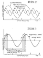
- piston-operated internal combustion engines have inherent imbalances which cause regularly occurring disturbances in the operation of the engine. Since one-half of the pistons drive the crank shaft during one complete engine revolution and the other, alternate one-half of the pistons drive the crank shaft during the subsequent revolution, and since these two sequences each have a discrete set of disturbances associated with them, the two revolutions will never have precisely the same characteristics. The crank shaft will always have a somewhat different amount of power transmitted to it during one full revolution than the one immediately preceding or following
- the inherent engine imbalances will produce a half order torsional having a full cycle during two full engine revolutions, a first order torsional occurring in one full engine revolution, a second order torsional occurring in one-half an engine revolution, and so on with higher order torsionals of decreasing magnitude.
- the result of the torsionals is that the instantaneous engine speed will vary as the engine rotates.
- the mass of the drive system and flywheel will damp the effect of the imbalances but the actual speed will still vary sinusoidally through two engine revolutions, with the engine alternately accelerating and decelerating.
- each signal being indicative of the average speed of the engine (so that the average speed can be quickly tracked during engine operation), in spite of the fact that the instantaneous engine speed will only be the same as the average speed once each full engine revolution, and will vary from the average speed during the rest of the engine revolution.
- the instantaneous speed of the engine is determined N/M times for each full revolution of the engine, N being an integer representing the number of times that a signal from the sensor 50 is generated during a full engine revolution, and M being either 1 or 2, depending upon whether a new, updated speed determination is made each time a sensor 50 signal is generated or whether a new, updated speed determination is made for every other sensor 50 signal.
- N/M consecutive instantaneous speed determination are then added and divided by (N/M)P, P being an integer representing a number of full engine revolutions, to obtain an average engine speed during the P number of engine revolutions.
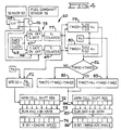
- Fig. 4 illustrates one embodiment of data processor 60 which can be used to generate average speed and average timing advance angle signals in response to generation of signals by the sensors 50 and 56.
- sensor 50 will generate a series of first signals 41 in response to each passage of a disc hole 47 therepast, with a time lapse of T, between consecutive leading edges of the signals.
- the fuel camshaft sensor 56 will likewise generate a series of second signals 55, each also having a time lapse of T i , between consecutive signals.
- the first and second signals 49 and 55 will be out of phase with each other in an amount dependent upon the position of the timing means 18, and there will be a time lapse of T 2 between the leading edge of a second signal 55 and the leading edge of the next successive first signal 49.
- the time lapse T is inversely proportional to engine speed: the faster the speed of engine rotation, the shorterthe time of T 1 and vice versa.
- the time lapse T 2 for any given phase relation between the timing and fuel camshaft 16 and 19, is also inversely proportional to engine speed.
- the ratio of T 2 /T 1 is proportional to the degree of phase relation between the timing and fuel camshafts 16 and 19, and will remain constant for any given degree of phase relation regardless of engine speed.
- a fixed frequency clock 65 generates a continuous series of high frequency clock pulses which are applied to the inputs of T, gate 66 and the T 2 gate 67.
- the first signals 49 from the disc sensor 50 are applied to flip-flop 68 so that a high Q flip-flop output from alternate first signals 49 will cause the T, gate 66 to close and a high Q flip-flop output from the next successive first signals 49 will cause the T 1 gate 66 to open.
- the count T, (t) i.e. the instantaneous count for 30° of engine revolution, in the T, counter is applied to divider 71, along with a constant K R , the divider 71 functioning to divide the constant K R by the count T l (t) and serving as a speed-indicating means for generating an instantaneous speed-indicating signal, SPD(t), which is inversely proportional to the count Ti(t) of the counter 66 and is thus directly proportional to the instantaneous engine speed measured during the time the T 1 gate 66 was closed.
- the constant K R is chosen to scale the Ti(t) count so that a useful eight-bit binary coded SPD(t) signal is obtained. This is accomplished once the-data is loaded into the register.
- the SPD(t) signal is then applied to the input cell of shift register 72, the shift register having NP/M number of cells.
- shift register 72 would have 12 cells.
- the successively generated speed-indicating signals SPD(t) will be applied to shift register 72 so that the shift register will have, at any time, the 12 most recent successive speed-indicating signals therein.
- the signals in all of the shift register cells are applied to the speed averaging means 73, shown here as an adder-divider, which adds the NP/M number of speed-indicating signals and divides the same by NP/M to generate an average speed signal.
- the adder-divider 73 outputs the average speed signal into the 8 bit latch 74 which stores such signal until the next average speed signal is generated.
- the latched signal may then be used in an engine control system as desired.
- the Q output of flip-flop 68 is also applied to AND gate 76 to enable the next successive second signal 55 from the fuel camshaft sensor 56 to close the T 2 gate 67.
- the T 2 gate 67 will be opened in response to the same first pulse 61 which opens the T 1 gate 66.
- the T 2 counter 77 will count clock pulses passing through gate 67 and will thus obtain a count of the number of clock pulses occurring in the time interval beginning with a second signal 55 and ending with the next successive first signal 49.
- the gates 66 and 67 and pulse counters 69 and 77 constitute a counting means 78 for counting clock pulses occurring in the time interval T 1 beginning and ending with consecutive first signal 49 from the pulse generating means 48 and for counting clock pulses occurring in the time interval T 2 beginning with a second signal 55 from pulse generating means 51 and ending with the next successive first signal 49 from pulse generating means 48.
- the timing means 18 When the engine is first started, the timing means 18 will be at minimum advance, e.g. 14° BTDC, and there will be an initial angular phase relation between the timing and fuel camshafts 16 and 19 to cause fuel delivery to the engine with minimum advance. Likewise, there will be an initial phase relation between the first signals 49 from the disc sensor 50 and the second signals 55 from the fuel camshaft sensor 56, corresponding to minimum advance, with a second signal 56 preceding the next successive first signal 55 by a particular degree of rotation. It is an aspect of the present embodiment that the circular member 52 on the fuel camshaft 19 can be randomly fixed thereto, without regard to whether its holes 53 have any particular orientation with respect to the holes 47 of the disc 45.
- the initial timing advance angle signal TIM(o) is then stored for use in the data processor 60 until the engine is shut down.
- the counts of counters 69 and 77 are applied to divider 80, which functions to generate an instantaneous timing advance signal each time following a new count by counters 69 and 77.
- divider 80 functions to generate an instantaneous timing advance signal each time following a new count by counters 69 and 77.
- 30° of engine rotation are required to develop the counts in counters 69 and 77 and a new timing advance signal TIM(t) will be generated in the next 30° of engine rotation. Accordingly, six new timing advance signals TIM(t) will be generated for each full engine revolution.
- the initial and instantaneous timing advance signals TIM(o) and TIM(t) are applied to logic circuit 81. If the magnitude of the instantaneous timing advance signal TIM(t) is not less than the magnitude of the initial timing advance signal TIM(o), function block 82 will subtract the initial timing advance signal TIM(o) from the instantaneous timing advance signal TIM(t) and generate a true timing advance signal TIM(t) which is proportional to the actual degree of timing advance produced by the timing means 18.
- function block 83 will add the angle K T to the instantaneous timing advance signal TIM(t) and then subtract the initial timing advance signal TIM(o) therefrom to generate a positive true timing signal TIM(T) which is proportional to the actual angle of advance from minimum advance.
- the successive true timing advance signals TIM(T) are entered into and advanced through the NP/M cell shift register 84. Each time a new TIM(T) signal is entered into shift register 84, the TIM(T) signals in the shift register cells are applied to adder-divider 85 which functions as an angle-averaging means for generating an average timing angle advance signal. Such signal is outputted into the 8-bit latch 86 which stores the signal until the next average timing advance angle signal is generated.
- the latched signal may be used in an engine control system as desired.
- Fig. 6 illustrates a modification of the system of Fig. 4, which may be used in an engine system wherein the timing advance means 18 is physically constrained so that a maximum timing advance of 20° from minimum advance is obtainable.
- the TIM(o) and TIM(t) timing advance angle signals are applied to the logic circuits 81 a and 81 b and the function blocks 82 and 83 are actuated in accordance with the logic circuits to generate the desired true timing advance signals TIM(T).
- the circular member 52 may be randomly fixed on the fuel camshaft 19, but the average speed and average timing advance signals will be updated only six times for each full engine revolution.
- the data processor 60a of Fig. 7, when used with the engine-fuel pump system of Fig. 1 enables the average speed and average timing advance signals to tbe updated twelve times for each full engine revolution (i.e. M 1), utilizing the same first and second rotation responsive means 46 and 51.
- the circular member 52 must be more accurately located on the fuel camshaft 19 (or the fixed location of the fixed sensors 49 and/or 55 must be more accurately chosen) so that at minimum timing advance a particular second signal 55 is generated slightly before a particular first signal 49 and at maximum timing advance such second signal is generated before the same first signal 49 but after the preceding first signal 49.
- the maximum timing advance is 20° from minimum, then the circular member 52 should be oriented on the full camshaft 19 so that, at minimum timing advance angle, a second signal 55 will be generated somewhere between one and nine degrees in advance of a first signal 49.
- the data processor 60a of Fig. 7 differs from that of Fig. 4 in that each second signal 55 from the fuel camshaft sensor 56 is used to close the T 2 gate 67, with the gate being opened by the next first signal 49 from the sensor 50.
- a new count by the T 2 counter 77 of the clock pulses from the fixed frequency clock 65 is obtained each time the engine rotates through 30°, or, twelve times during a full engine rotation.
- the data processor 60a also differs in that gate 66 is closed by each first signal 49 from the sensor 50 and is opened by the next occurring second signal 55 from the fuel camshaft sensor 56. The clock pulses during this period are then counted by the T 3 counter 69a, with the count being proportional to the length of this time period.
- the T 3 count is sent to adder 69b, enabling the T 3 counter 69a to be reset.
- the time periods T 2 +T 3 will always equal the time period T 1 .
- gates 66 and 67, pulse counters 69a and 77 and adder 69b constitute counting means 78 for counting clock pulses occurring in the time interval T 1 beginning and ending with consecutive first signals from the pulse generating means 48 and for counting clock pulses occurring in the time interval T 2 beginning with a second signal 55 from pulse generating means 51 and ending with the next successive first-signal 49 from pulse generating means 48.
- the T 1 signal from adder 69b, generated for each 30° of engine revolution, is then sent to divider 71, and an average speed indicating signal is generated by the shift register 72 (having 24 cells) and adder-divider 73 as before.
- 24 instantaneous speed indicating signals will be averaged for two full engine revolutions and a new average speed indicating signal will be generated for each successive 30° of engine revolution.
- the T 1 signal from adder 69b and the T 2 signal from counter 77 will also be applied, as before, to dividers 79 and 80 wherein an initial timing advance signal TIM(o) and subsequent instantaneous timing advance signals TIM(t) are generated.
- the TIM(T) signals are sent successively to 24-cell shift register 84 and the 24 signals occurring during two full revolutions of the engine are averaged by adder-divider 85 and latched into the 8-bit latch 86, once for each successive 30° of engine rotation.
- the present invention provides a system wherein digital information as to the true speed and timing advance angle of an internal combustion engine can be easily obtained, with the effects of engine torsionals cancelled out, and with such information being constantly updated many times during a single revolution of the engine.
- Such system is particularly useful in electronic engine control systems wherein it is necessary to know the true engine speed and timing advance angle in order to regulate the fuel control of the engine for maximum efficiency of operation with minimum exhaust emissions.
Description
- This invention relates to apparatus for determining the actual speed of a rotating shaft and the relative angular relationship between that shaft and a further shaft driving or driven by it. The invention has particular application in the field of internal combustion engines.
- Basic control of the operation of an internal combustion engine is accomplished by varying the amount of fuel delivered to the engine cylinder by the fuel pump and by controlling the time that the fuel in the cylinder ignites as the pistons approach top dead centre on the compression stroke. In general, the amount of fuel delivered to the cylinders will control the speed of the engine while the timing of ignition will control the efficiency of fuel combustion.
- In a typical four-stroke-cycle diesel engine a timing shaft is gear driven by the engine crankshaft at half engine speed, with the timing shaft being coupled to the drive shaft of a fuel pump by a timing mechanism so that the fuel pump will deliver fuel to half of the engine cylinders during one engine revolution and to the other half of the cylinders during the next revolution. A controllable fuel rack will vary the amount of fuel that the fuel pump delivers to the engine cylinders and a timing mechanism can be used to vary the angular relation between the timing shaft and the fuel pump drive shaft so that fuel is injected into the cylinders at the proper time in engine operation relative to the pistons reaching top dead centre on their compression strokes.
- In order to provide an electronic engine control system which will function to maintain engine performance at maximum efficiency under varying operating conditions, it is necessary to obtain precise information as to the actual engine speed and the magnitude of the timing advance angle.
- Furthermore, for an engine control system to be effective, the system must have a rapid response time, with speed and timing advance angle information being updated many successive times during a single revolution of the engine.
- There are a number of problems involved in providing suitable apparatus for obtaining the desired engine speed and timing advance information.
- First, the apparatus should have a life which meets or exceeds engine overhaul time to prevent premature failutre and loss of control. To meet this requirement, the components utilized for detection of speed and angular displacement of the fuel camshaft need to be simple, rugged and non-contacting.
- The presence of engine torsionals presents a significant problem in providing accurate information as to engine speed and timing advance angle. Briefly the problem is that internal combustion engines have inherent imbalances causing the instantaneous speed of the engine to vary sinusoidally during a sequential operation of the pistons, with the engine being accelerated during operation of one half of the pistons and decelerated during the successive operation of the other half of the pistons. If the engine is operating at a given average speed, and if the instantaneous engine speed is determined once for, and at the same time during, each full cycle of sinusoidal operation, each successive instantaneous speed determination will be the same as before. Likewise, if the average engine speed should vary, the instantaneous speed determination will vary directly therewith.
- However, if a speed determination is made more frequently than once during a full cycle of sinusoidal operation, as is desired in the present invention, the successive instantaneous speed determinations will vary from one another even though the average engine speed remains the same. Thus, in order to obtain useful speed information many times successively during a full sinusoidal cycle of engine operation, the effect of the engine torsionals must be cancelled out so that each successive bit of information will have the same relationship to the average engine speed.
- Measurements of the timing advance angle have been made by a first sensor operable to detect movement of a fixed point on the timing shaft and a second sensor operable to detect movement of a fixed point on the fuel pump drive shaft, and by means to measure the time between actuation of the two sensors. The time lapse is related to the phase angle between the shafts produced by the timing mechanism and can thus be used to provide information as to the mag- nitude of the timing advance angle. However, such systems as have been devised heretofore require careful initial mechanical adjustment of the sensor systems in order to provide accurate timing advance angle information. Accordingly it is desirable to provide a similar sensor system for timing advance angle determination which does not require such initial adjustment.
- Speed and timing advance angle determination systems which provide analog information are inherently inaccurate, since age and varying temperature conditions will often cause component values to change. Thus it is desirable for the system to operate on digital information.
- GB-A-1439553 from which the preamble of
present Claim 1 has been derived discloses an apparatus and method for measuring the relative phase shift between two pulse trains of the samevariable frequency 1/T, wherein counting the number of pulses occurring during a certain time interval in one of the pulse trains takes place, and wherein the time t between a pulse in one train and a subsequently occurring pulse in the second train is registered by pulses of known frequency proportional in number to this time. The relative phase shift is tsΓ. US-A-4179922 discloses apparatus wherein a succession of electrical pulses are provided, corresponding to successive crankshaft positions, circuitry being provided for responding to the pulses for the purpose of measuring the time interval between successive pulses. - According to the invention there is provided a system having first and second rotatable shafts and timing means rotatably linking one of the shafts to the other and for varying, within a predetermined range the angular relationship between the shafts, comprises:
- a first circular member rotating in use about its centre at a speed proportional to the speed of the first shaft and providing a plurality of equiangularly spaced first members movable through a first circular path;
- a first signal generating means for generating a first signal in response to movement of each first member past a predetermined point in the first circular path;
- a second circular member rotating about its centre at a speed proportional to the speed of the second shaft and providing a plurality of equiangularly spaced second members, movable through a second circular path;
- a second signal generating means for generating a second signal in response to movement of each second member past a predetermined point in the second circular path;
- clock means for generating a series of fixed frequency clock pulses;
counting means for: - a) obtaining a first count of the number of clock pulses occurring in the time interval beginning and ending with consecutive signals from one of the signal generators; and
- b) obtaining a second count of the number of clock pulses occurring in the time interval beginning with a signal from one of the signal generators and ending with a successive signal from the other of the signal generators;
- and angle-indicating means for generating an angle-indication signal proportional to the ratio of the first and second counts of the counting means to provide an indication of the relative timing between the shafts; characterised in that:
- the number of first and second members is such that N number of each of the first and second signals are generated during one full revolution of one of the first and second shafts, N being an integer, the counting means is arranged to obtain N/M number of successive first and second counts during one full revolution, M being an integer, and the angle-indicating means generates N/M number of successive angle-indicating signals during one full revolution, and characterised by angle-averaging means for generating an average-angle signal equal to the sum of NP/M number of successive angle-indicating signals divided by the number NP/M, wherein P is an integer representing a predetermined number of successive full revolutions.
- The sinusoidal torsional effects may be averaged out by obtaining many successive angle-indicating and/or speed-indicating signals during a full revolution of the shafts, and each time new signals are obtained, a predetermined number of successive signals are added together and divided by the predetermined number.
- The first count may be obtained by counting the number of clock pulses occurring between the signal from one of the signal generators and the next signal from the other of the signal generators, by counting the number of clock pulses occurring between the next signal from the other of the signal generators and the next signal from the one of the signal generators, and by adding these two numbers of clock pulses together.
- An initial angle-indicating signal may be obtained corresponding to a minimum advance angle and may be compared to subsequently obtained angle-indicating signals to derive a signal corresponding to the actual angle advance from minimum advance.
- In the drawings, forming a part of this application and in which like parts are designated by like reference numerals throughout the same,
- Fig. 1 is a generally schematic illustration of an engine and fuel pump system utilising the present invention;
- Fig. 2 is a graph illustrating the effect of engine torsionals;
- Fig. 3 is a graph illustrating the torsional cancellation technique of the present invention;
- Fig. 4 is a block diagram of one form of the data processing of Fig. 1;
- Fig. 5 is a timing chart of the signals produced by the sensor and fuel camshaft sensor and used in the data processor of Fig. 4;
- Fig. 6 is a modification of a portion of the data processor of Fig. 4;
- Fig. 7 is a block diagram of an alternative form of the data processor of Fig. 1; and
- Fig. 8 is a timing chart of the signals produced by the sensor and fuel camshaft sensor and used in the data processor of Fig. 7.
- Referring now to the drawings wherein preferred embodiments of the invention are shown, Fig. 1 illustrates schematically an
internal combustion engine 10, such as a four-stroke-cycle diesel engine, the engine having acrank shaft 11 to whichcircular flywheel member 12 is fixed for rotation at a speed equal to the engine speed. Meshedgears 13 and 14, oncrank shaft 11 and timing shaft 16 respectively, are provided to transmit engine rotation to the timing shaft 16. As is seen,engine 10,crank shaft 11 andgears 13 and 14 constitute a drive means 17 for driving a timing shaft 16 at a rotational speed directly proportional to the engine speed, the contant of proportionality being dependent on the gear ratio ofgears 13 and 14. For a four-stroke-cycle diesel engine the gear ratio is such that the timing shaft 16 is driven at half the speed of the engine. - A
timing means 18 is provided to rotatively drivefuel camshaft 19 offuel pump 21 by timing shaft 16 and to vary, within a predetermined range, the angular relationship between the timing shaft 16 andfuel camshaft 19. As illustrated in Fig. 1, timing means 18 may comprisegears fuel camshaft 19, respectively, with the drive ofgear 23 being transmitted togear 24 bygears gears spindle 28. Spindle 28 is biased towards a zero reference fixedstop 29 byspring 31. The system is initially bench set so that when thespindle 28 is against thestop 29, thefuel camshaft 19 will cause thefuel pump 21 to deliver fuel fromfuel tank 32 andfuel line 33 to theengine 10 at a minimum advance (typically 14°) before top dead center of the engine pistons. Of course, other types of differential type units could also be employed to control this angular relationship. - The timing means 18 will cause the timing advance angle of fuel delivery to be set at a desired value greater than minimum during operation of the
engine 10 as by actuation of valve 34 in response to timing advance actuator 36, so thatpiston 37 ofhydraulic cylinder 38 will extend or retract and causegear spindle 28 to move to a desired position away fromstop 29. At such desired position,gears fuel camshaft 19 to be drive at the same speed as that of timing shaft 16, but the angular relationship of the two shafts will have been increased from the minimum advance relationship. -
Fuel pump 21 has amovable fuel rack 41, controlled byfuel rack actuator 42, to control the amount of fuel flow through the fuel pump. - A first rotation
responsive means 46 is provided for generating a signal each successive time thatengine 10 rotates through 360/N degrees, N being an integer. As illustrated here, the rotation responsive means 46 includes a plurality of holes 47 in adisc 45, equi-angularly spaced relative to, and equi-distally spaced from the axis of the flywheel. Thisdisc 45 is axled on the timing shaft 16 at a position between gear 14 andgear 23. Holes 47 indisc 45 thus provide irregularities on the ferromagnetic disc which constitute magnetically-sensible members which rotate in a circular path around timing shaft 16. Similarly,disc 45 could be a gear, the teeth of which serve as magnetically-sensible members. - Rotation responsive means 46 also includes a first signal generating means 48 for generating a first signal 49 (Fig. 5) in response to each movement of a hole 47 past a predetermined point in the circular path of movement of holes 47. In particular the signal generating means 48 includes a fixed
magnetic sensor 50 located adjacent the circular path of movement, the location of thesensor 50 thus determining the predetermined point in the path of movement of holes 47. - As illustrated,
disc 45 has 24 holes 47, thus afirst signal 49 will be generated each time the timing shaft 16 rotates through 360/24, or 15 degrees. Since timing shaft 16 is driven at half engine speed, a first signal will be generated each time the engine rotates through 30 degrees. - A second rotation responsive means 51 is provided for generating a second signal each successive time that the engine has rotated through 360/N degrees. As illustrated here, the rotation responsive means 51 includes a circular,
ferromagnetic disk member 52 fixed tofuel camshaft 19 for rotation therewith,circular member 52 having a plurality ofholes 53 equiangularly spaced aroundmember 24 and equidistant from the axis ofcamshaft 19. As before, holes 53 provide magnetically-sensible, surface irregularity members which move in a circular path aroundcamshaft 19. - Rotation responsive means 51 also includes a second signal generating means 54 for generating a second signal 55 (Fig. 5) in response to each movement of a
hole 53 past a predetermined point in the circular path of movement ofholes 53. As illustrated, the signal generating means 54 includes a fixedmagnetic sensor 56 located adjacent the circular path of movement ofholes 53. Again, the fixed location of thesensor 56 determines the predetermined point in the path of movement ofholes 53. - As illustrated, the
circular member 53 has twenty-fourholes 53, and thus asecond signal 55 will be generated for each 15 degrees of rotation ofcamshaft 19. Or, sincefuel camshaft 19 is driven at half engine speed, a second signal will be generated for each 30 degrees of rotation ofengine 10. - With the illustrated system, the number of
first signals 49 from theflywheel sensor 50 will be equal to the number ofsecond signals 55 from thefuel camshaft sensor 56 during any given length of time, such as the time that it takes the engine crankshaft 11, or the time that it takes either of the timing orfuel camshaft 16 or 19, to rotate through a full revolution, and the time interval between consecutive first signals will be equal to the time interval between consecutive second signals. The phase relationship of the first andsecond signals - The first and second signals from the
sensor 50 andfuel camshaft sensor 56 are then sent to thedata processor 60 wherein the signals are used to generate digital signals proportional to the engine speed and the timing advance angle of thefuel pump 21. - In a further embodiment of the invention, the engine speed and timing advance angle signals are also generated in a manner so as to cancel out the effect of engine torsionals. As previously mentioned, piston-operated internal combustion engines have inherent imbalances which cause regularly occurring disturbances in the operation of the engine. Since one-half of the pistons drive the crank shaft during one complete engine revolution and the other, alternate one-half of the pistons drive the crank shaft during the subsequent revolution, and since these two sequences each have a discrete set of disturbances associated with them, the two revolutions will never have precisely the same characteristics. The crank shaft will always have a somewhat different amount of power transmitted to it during one full revolution than the one immediately preceding or following
- As is seen in Fig. 2, the inherent engine imbalances will produce a half order torsional having a full cycle during two full engine revolutions, a first order torsional occurring in one full engine revolution, a second order torsional occurring in one-half an engine revolution, and so on with higher order torsionals of decreasing magnitude. The result of the torsionals is that the instantaneous engine speed will vary as the engine rotates. The mass of the drive system and flywheel will damp the effect of the imbalances but the actual speed will still vary sinusoidally through two engine revolutions, with the engine alternately accelerating and decelerating.
- In the present apparatus, it is desired to obtain rapidly recurring signals, for example at 6 or 12 times each engine revolution, each signal being indicative of the average speed of the engine (so that the average speed can be quickly tracked during engine operation), in spite of the fact that the instantaneous engine speed will only be the same as the average speed once each full engine revolution, and will vary from the average speed during the rest of the engine revolution.
- The technique used in the present invention to cancel out the effect of engine torsionals is illustrated in Fig. 3.
- The instantaneous speed of the engine is determined N/M times for each full revolution of the engine, N being an integer representing the number of times that a signal from the
sensor 50 is generated during a full engine revolution, and M being either 1 or 2, depending upon whether a new, updated speed determination is made each time asensor 50 signal is generated or whether a new, updated speed determination is made for everyother sensor 50 signal. (N/M)P consecutive instantaneous speed determination are then added and divided by (N/M)P, P being an integer representing a number of full engine revolutions, to obtain an average engine speed during the P number of engine revolutions. - For example, if the speed determinations are to be averaged over two full engine revolutions (P=2) and a rotation responsive means 46 is used with 24 holes 47 in the disc 45 (N=12, since
disc 45 turns at half engine speed), and a speed determination is made for each time (M=1) thesensor 50 senses the movement of a hole 47 therepast (as in Figs. 7 and 8), then 24 successive speed determinations will be averaged. As seen in Fig. 3, if the instantaneous speed determinations at the 24 sampling points in the sampling period beginning with "a" and ending with "a"' are taken, half of the instantaneous speed determination will be greater and half will be less than the average engine speed, so that when averaged, the 24 speed determinations will equal the average speed of the engine for the sampling period. The same will be true for any of the other sampling periods b-b', c-c', and so forth. - As is also apparent, if the speed averaging is done at each point a', b', c' and so on, then the average engine speed will be updated each time the engine has rotated through 360/N degrees, or 30 degrees.
- If an instantaneous speed determination is made for every other hole 47 (M=2), as in Figs. 4 and 5, then twelve speed determinations will be made and averaged, e.g. at a, c, e and so on, for two full engine revolutions. The successive averagings will again each be equal to the actual average engine speed, but the average engine speed information will only be available for every 60 degrees of engine rotation.
- Fig. 4 illustrates one embodiment of
data processor 60 which can be used to generate average speed and average timing advance angle signals in response to generation of signals by thesensors sensor 50 will generate a series offirst signals 41 in response to each passage of a disc hole 47 therepast, with a time lapse of T, between consecutive leading edges of the signals. Thefuel camshaft sensor 56 will likewise generate a series ofsecond signals 55, each also having a time lapse of Ti, between consecutive signals. The first andsecond signals second signal 55 and the leading edge of the next successivefirst signal 49. The time lapse T, is inversely proportional to engine speed: the faster the speed of engine rotation, the shorterthe time of T1 and vice versa. The time lapse T2, for any given phase relation between the timing andfuel camshaft 16 and 19, is also inversely proportional to engine speed. The ratio of T2/T1 is proportional to the degree of phase relation between the timing andfuel camshafts 16 and 19, and will remain constant for any given degree of phase relation regardless of engine speed. - In the
data processor 60 of Fig. 4, a fixedfrequency clock 65 generates a continuous series of high frequency clock pulses which are applied to the inputs of T,gate 66 and the T2 gate 67. The first signals 49 from thedisc sensor 50 are applied to flip-flop 68 so that a high Q flip-flop output from alternatefirst signals 49 will cause the T,gate 66 to close and a high Q flip-flop output from the next successivefirst signals 49 will cause the T1 gate 66 to open. - During the time the T,
gate 66 is closed, clock pulses fromclock 65 will pass through the gate to the T1 pulse counter 69 and be counted. When the T1 gate is then opened, the T,pulse counter 69 will have a count of the number of clock pulses occurring during the time interval beginning and ending with successive first signals 49. Sinceclock 65 has a fixed frequency, the count of T,pulse counter 69 will be inversely proportional to the speed of the engine. - After the T, gate has opened, the count T, (t) i.e. the instantaneous count for 30° of engine revolution, in the T, counter is applied to
divider 71, along with a constant KR, thedivider 71 functioning to divide the constant KR by the count Tl(t) and serving as a speed-indicating means for generating an instantaneous speed-indicating signal, SPD(t), which is inversely proportional to the count Ti(t) of thecounter 66 and is thus directly proportional to the instantaneous engine speed measured during the time the T1 gate 66 was closed. The constant KR is chosen to scale the Ti(t) count so that a useful eight-bit binary coded SPD(t) signal is obtained. This is accomplished once the-data is loaded into the register. - The SPD(t) signal is then applied to the input cell of
shift register 72, the shift register having NP/M number of cells. In the embodiment presently described,shift register 72 would have 12 cells. As the engine continues to rotate, the successively generated speed-indicating signals SPD(t) will be applied toshift register 72 so that the shift register will have, at any time, the 12 most recent successive speed-indicating signals therein. - Each time a new SPD(t) signal has been entered into
shift register 72, the signals in all of the shift register cells are applied to the speed averaging means 73, shown here as an adder-divider, which adds the NP/M number of speed-indicating signals and divides the same by NP/M to generate an average speed signal. The adder-divider 73 outputs the average speed signal into the 8bit latch 74 which stores such signal until the next average speed signal is generated. The latched signal may then be used in an engine control system as desired. - During the time that the T1 gate 66 has been closed by the high Q output of flip-
flop 68 in response to a first pulse 61, the Q output of flip-flop 68 is also applied to ANDgate 76 to enable the next successivesecond signal 55 from thefuel camshaft sensor 56 to close the T2 gate 67. The T2 gate 67 will be opened in response to the same first pulse 61 which opens the T1 gate 66. - During the time the T2 gate is closed, the T2 counter 77 will count clock pulses passing through
gate 67 and will thus obtain a count of the number of clock pulses occurring in the time interval beginning with asecond signal 55 and ending with the next successivefirst signal 49. - As may be seen, the
gates first signal 49 from the pulse generating means 48 and for counting clock pulses occurring in the time interval T2 beginning with asecond signal 55 from pulse generating means 51 and ending with the next successivefirst signal 49 from pulse generating means 48. - When the engine is first started, the timing means 18 will be at minimum advance, e.g. 14° BTDC, and there will be an initial angular phase relation between the timing and
fuel camshafts 16 and 19 to cause fuel delivery to the engine with minimum advance. Likewise, there will be an initial phase relation between thefirst signals 49 from thedisc sensor 50 and thesecond signals 55 from thefuel camshaft sensor 56, corresponding to minimum advance, with asecond signal 56 preceding the next successivefirst signal 55 by a particular degree of rotation. It is an aspect of the present embodiment that thecircular member 52 on thefuel camshaft 19 can be randomly fixed thereto, without regard to whether itsholes 53 have any particular orientation with respect to the holes 47 of thedisc 45. For example, in one engine, for a given timing advance angle, it might take 10° of engine rotation between asecond signal 55 and the next successivefirst signal 49, whereas in another engine, and with the same timing advance, it might require 20° of engine rotation between asecond signal 55 and the next successivefirst signal 49. - In any given system, however, with the
disc 45 fixed to timing shaft 16 and thecircular member 52 fixed to thefuel camshaft 19, and with thesensor members sensible holes 47 and 53, the angle through which the engine must turn, between asecond signal 55 and the next succeedingfirst signal 49, will be the same for any given degree of timing advance angle. - At engine start up, the engine will initially operate at minimum advance angle. The counts of both
counters divider 79, along with a constant KTr thedivider 79 functioning to generate an initial, or reference, timing advance angle signal -

second signal 55 and the next succeedingfirst signal 49 relative to the degree of engine rotation between consecutive first signals 49. Such signal is thus independent of engine speed. The constant KT scales that divided count to provide a useful binary coded signal, with the constant KT also representing the angle that the engine turns between successive first signals. Thus, in the particular system shown, if T,=T2, then the signal TIM would represent a timing advance of 30°. - The initial timing advance angle signal TIM(o) is then stored for use in the
data processor 60 until the engine is shut down. - After the initial timing advance angle signal TIM(o) has been generated, the counts of
counters divider 80, which functions to generate an instantaneous timing advance signal
counters counters - The initial and instantaneous timing advance signals TIM(o) and TIM(t) are applied to
logic circuit 81. If the magnitude of the instantaneous timing advance signal TIM(t) is not less than the magnitude of the initial timing advance signal TIM(o),function block 82 will subtract the initial timing advance signal TIM(o) from the instantaneous timing advance signal TIM(t) and generate a true timing advance signal TIM(t) which is proportional to the actual degree of timing advance produced by the timing means 18. If the instantaneous timing advance signal TIM(t) is less than the initial timing advance signal TIM(o), then functionblock 83 will add the angle KT to the instantaneous timing advance signal TIM(t) and then subtract the initial timing advance signal TIM(o) therefrom to generate a positive true timing signal TIM(T) which is proportional to the actual angle of advance from minimum advance. - The successive true timing advance signals TIM(T) are entered into and advanced through the NP/M
cell shift register 84. Each time a new TIM(T) signal is entered intoshift register 84, the TIM(T) signals in the shift register cells are applied to adder-divider 85 which functions as an angle-averaging means for generating an average timing angle advance signal. Such signal is outputted into the 8-bit latch 86 which stores the signal until the next average timing advance angle signal is generated. The latched signal may be used in an engine control system as desired. - Fig. 6 illustrates a modification of the system of Fig. 4, which may be used in an engine system wherein the timing advance means 18 is physically constrained so that a maximum timing advance of 20° from minimum advance is obtainable. In this case, the TIM(o) and TIM(t) timing advance angle signals are applied to the

logic circuits - As explained above, when the
data processor 60 of Fig. 4 is used with the engine-fuel pump system of Fig. 1, thecircular member 52 may be randomly fixed on thefuel camshaft 19, but the average speed and average timing advance signals will be updated only six times for each full engine revolution. - The data processor 60a of Fig. 7, when used with the engine-fuel pump system of Fig. 1 enables the average speed and average timing advance signals to tbe updated twelve times for each full engine revolution (i.e. M=1), utilizing the same first and second rotation responsive means 46 and 51. In this embodiment, however, the
circular member 52 must be more accurately located on the fuel camshaft 19 (or the fixed location of the fixedsensors 49 and/or 55 must be more accurately chosen) so that at minimum timing advance a particularsecond signal 55 is generated slightly before a particularfirst signal 49 and at maximum timing advance such second signal is generated before the samefirst signal 49 but after the precedingfirst signal 49. For example, if the maximum timing advance is 20° from minimum, then thecircular member 52 should be oriented on thefull camshaft 19 so that, at minimum timing advance angle, asecond signal 55 will be generated somewhere between one and nine degrees in advance of afirst signal 49. - The data processor 60a of Fig. 7 differs from that of Fig. 4 in that each
second signal 55 from thefuel camshaft sensor 56 is used to close the T2 gate 67, with the gate being opened by the nextfirst signal 49 from thesensor 50. Thus, a new count by the T2 counter 77 of the clock pulses from the fixedfrequency clock 65 is obtained each time the engine rotates through 30°, or, twelve times during a full engine rotation. - The data processor 60a also differs in that
gate 66 is closed by eachfirst signal 49 from thesensor 50 and is opened by the next occurringsecond signal 55 from thefuel camshaft sensor 56. The clock pulses during this period are then counted by the T3 counter 69a, with the count being proportional to the length of this time period. - After the T3 count has been obtained and during the time that the T2 counter 77 is counting clock pulses, the T3 count is sent to adder 69b, enabling the T3 counter 69a to be reset. After the T2 count has been obtained by
counter 77, it too is sent to adder 69b and a T,=T2+T3 signal is generated during the time the next T3 count is being obtained. As is seen in Fig. 8, regardless of the time relation of the sensor signals 49 and 55, the time periods T2+T3 will always equal the time period T1. - Thus,
gates adder 69b constitute counting means 78 for counting clock pulses occurring in the time interval T1 beginning and ending with consecutive first signals from the pulse generating means 48 and for counting clock pulses occurring in the time interval T2 beginning with asecond signal 55 from pulse generating means 51 and ending with the next successive first-signal 49 from pulse generating means 48. - The T1 signal from
adder 69b, generated for each 30° of engine revolution, is then sent todivider 71, and an average speed indicating signal is generated by the shift register 72 (having 24 cells) and adder-divider 73 as before. In this case, 24 instantaneous speed indicating signals will be averaged for two full engine revolutions and a new average speed indicating signal will be generated for each successive 30° of engine revolution. - The T1 signal from
adder 69b and the T2 signal from counter 77 will also be applied, as before, todividers - Since the
circular member 52 on thefuel camshaft 19 is oriented so that the instantaneous timing advance signal TIM(t) is always greater in magnitude than the initial timing advance signal TIM(o), these signals are then sent directly to functionblock 82 wherein is generated the instantaneous true timing advance signal
- The TIM(T) signals are sent successively to 24-
cell shift register 84 and the 24 signals occurring during two full revolutions of the engine are averaged by adder-divider 85 and latched into the 8-bit latch 86, once for each successive 30° of engine rotation. - The present invention provides a system wherein digital information as to the true speed and timing advance angle of an internal combustion engine can be easily obtained, with the effects of engine torsionals cancelled out, and with such information being constantly updated many times during a single revolution of the engine.
- Such system is particularly useful in electronic engine control systems wherein it is necessary to know the true engine speed and timing advance angle in order to regulate the fuel control of the engine for maximum efficiency of operation with minimum exhaust emissions.
Claims (10)
counting means (78) for:
when TIM(t)≥ TIM(0), and
when TIM(t)<TIM(0).
Applications Claiming Priority (2)
| Application Number | Priority Date | Filing Date | Title |
|---|---|---|---|
| WOPCT/US81/00268 | 1981-03-03 | ||
| PCT/US1981/000268 WO1982003125A1 (en) | 1981-03-03 | 1981-03-03 | Speed and timing angle measurement |
Publications (3)
| Publication Number | Publication Date |
|---|---|
| EP0059585A2 EP0059585A2 (en) | 1982-09-08 |
| EP0059585A3 EP0059585A3 (en) | 1985-12-04 |
| EP0059585B1 true EP0059585B1 (en) | 1989-04-05 |
Family
ID=22161121
Family Applications (1)
| Application Number | Title | Priority Date | Filing Date |
|---|---|---|---|
| EP82300906A Expired EP0059585B1 (en) | 1981-03-03 | 1982-02-23 | Timing angle and speed measurement of shafts |
Country Status (4)
| Country | Link |
|---|---|
| EP (1) | EP0059585B1 (en) |
| JP (1) | JPS58500335A (en) |
| DE (1) | DE3279595D1 (en) |
| WO (1) | WO1982003125A1 (en) |
Cited By (6)
| Publication number | Priority date | Publication date | Assignee | Title |
|---|---|---|---|---|
| FR2566912A1 (en) * | 1984-06-05 | 1986-01-03 | Mtu Friedrichshafen Gmbh | METHOD FOR MEASURING, BY ELECTRONIC MEANS, THE ACTUAL SPEED OF ROTATION OF A PISTON ENGINE |
| FR2591752A1 (en) * | 1985-12-12 | 1987-06-19 | Gen Electric | SPEED AND PHASE MEASUREMENT SYSTEM FOR AIRCRAFT HELICOS |
| US5112191A (en) * | 1989-04-11 | 1992-05-12 | General Electric Company | Rotating cowling |
| EP1189065A1 (en) * | 2000-09-11 | 2002-03-20 | Denso Corporation | Wheel speed sensor |
| DE10122517C1 (en) * | 2001-05-09 | 2002-06-20 | Mtu Friedrichshafen Gmbh | Rev filter for IC engine incorporates full or partial elimination of rotational vibration of first order |
| DE10221681A1 (en) * | 2002-05-16 | 2003-11-27 | Mtu Friedrichshafen Gmbh | Regulation of the voltage generator of an internal combustion engine is made by measuring actual speed and applying a control action to eliminate oscillation |
Families Citing this family (5)
| Publication number | Priority date | Publication date | Assignee | Title |
|---|---|---|---|---|
| DE3506233A1 (en) * | 1984-03-20 | 1985-10-31 | Volkswagenwerk Ag, 3180 Wolfsburg | Method and device for digital measurement of the rotational speed of rotating components |
| JPS6130770A (en) * | 1984-07-24 | 1986-02-13 | Diesel Kiki Co Ltd | Vehicle detector |
| US5222022A (en) * | 1986-12-01 | 1993-06-22 | Woodward Governor Company | Method and apparatus for iterated determinations of sensed speed and speed governing |
| DE4113958C2 (en) * | 1991-04-29 | 1995-12-21 | Kloeckner Humboldt Deutz Ag | Fuel injector |
| WO2015069998A1 (en) * | 2013-11-11 | 2015-05-14 | General Electric Company | Method for reducing error in rotor speed measurements |
Citations (1)
| Publication number | Priority date | Publication date | Assignee | Title |
|---|---|---|---|---|
| GB1439553A (en) * | 1973-04-16 | 1976-06-16 | Sem Sandberg S G | Method and an apparatus for measuring relative phase shift between two pulse trains |
Family Cites Families (12)
| Publication number | Priority date | Publication date | Assignee | Title |
|---|---|---|---|---|
| US3184668A (en) * | 1963-02-15 | 1965-05-18 | Smith Kline French Lab | Master-slave plural motor synchronizing system |
| JPS4514782Y1 (en) * | 1966-04-08 | 1970-06-22 | ||
| JPS5339528B1 (en) * | 1971-03-06 | 1978-10-21 | ||
| JPS5325265B1 (en) * | 1971-06-15 | 1978-07-26 | ||
| DE2403886A1 (en) * | 1974-01-28 | 1975-08-07 | Siemens Ag | Circuitry for continuous treatment of vehicle speed valves - gives conversion from analogue form to digital average valves |
| JPS51981A (en) * | 1974-06-20 | 1976-01-07 | Mitsubishi Electric Corp | Sokudohatsudenkino koshokenshutsukairo |
| JPS5134939A (en) * | 1974-09-19 | 1976-03-25 | Adeka Argus Chemical Co Ltd | HAROGENGAN JUJUSHI SEIBUTSU |
| DE2500061A1 (en) * | 1975-01-02 | 1976-07-08 | Dunlop Ag | DEVICE FOR SLIP MEASUREMENT |
| JPS5946676B2 (en) * | 1976-08-23 | 1984-11-14 | 日本アブコ−株式会社 | Method for treating metal ion-containing solutions using a combination of ultrafiltration membrane and reverse osmosis membrane |
| US4179922A (en) * | 1977-03-25 | 1979-12-25 | Harris Corporation | Data acquisition for use in determining malfunctions of cylinders of an internal combustion engine |
| JPS5436961A (en) * | 1977-08-29 | 1979-03-19 | Nissan Motor | Angleeoffrotation detector |
| JPS5516277A (en) * | 1978-07-21 | 1980-02-04 | Nippon Denso Co Ltd | Rotary location detector for internal combustion engine |
-
1981
- 1981-03-03 WO PCT/US1981/000268 patent/WO1982003125A1/en unknown
- 1981-03-03 JP JP50212081A patent/JPS58500335A/en active Pending
-
1982
- 1982-02-23 DE DE8282300906T patent/DE3279595D1/en not_active Expired
- 1982-02-23 EP EP82300906A patent/EP0059585B1/en not_active Expired
Patent Citations (1)
| Publication number | Priority date | Publication date | Assignee | Title |
|---|---|---|---|---|
| GB1439553A (en) * | 1973-04-16 | 1976-06-16 | Sem Sandberg S G | Method and an apparatus for measuring relative phase shift between two pulse trains |
Cited By (9)
| Publication number | Priority date | Publication date | Assignee | Title |
|---|---|---|---|---|
| FR2566912A1 (en) * | 1984-06-05 | 1986-01-03 | Mtu Friedrichshafen Gmbh | METHOD FOR MEASURING, BY ELECTRONIC MEANS, THE ACTUAL SPEED OF ROTATION OF A PISTON ENGINE |
| FR2591752A1 (en) * | 1985-12-12 | 1987-06-19 | Gen Electric | SPEED AND PHASE MEASUREMENT SYSTEM FOR AIRCRAFT HELICOS |
| US5112191A (en) * | 1989-04-11 | 1992-05-12 | General Electric Company | Rotating cowling |
| EP1189065A1 (en) * | 2000-09-11 | 2002-03-20 | Denso Corporation | Wheel speed sensor |
| DE10122517C1 (en) * | 2001-05-09 | 2002-06-20 | Mtu Friedrichshafen Gmbh | Rev filter for IC engine incorporates full or partial elimination of rotational vibration of first order |
| US6873941B2 (en) | 2001-05-09 | 2005-03-29 | Mtu Friedrichshafen Gmbh | Speed filter |
| DE10221681A1 (en) * | 2002-05-16 | 2003-11-27 | Mtu Friedrichshafen Gmbh | Regulation of the voltage generator of an internal combustion engine is made by measuring actual speed and applying a control action to eliminate oscillation |
| DE10221681B4 (en) * | 2002-05-16 | 2005-12-08 | Mtu Friedrichshafen Gmbh | Method for controlling an internal combustion engine-generator unit |
| US6994074B2 (en) | 2002-05-16 | 2006-02-07 | Mtu Friedrichshafen Gmbh | Method for controlling an internal combustion engine generator unit |
Also Published As
| Publication number | Publication date |
|---|---|
| DE3279595D1 (en) | 1989-05-11 |
| EP0059585A3 (en) | 1985-12-04 |
| WO1982003125A1 (en) | 1982-09-16 |
| EP0059585A2 (en) | 1982-09-08 |
| JPS58500335A (en) | 1983-03-03 |
Similar Documents
| Publication | Publication Date | Title |
|---|---|---|
| US4417469A (en) | Speed and timing angle measurement | |
| US4368705A (en) | Engine control system | |
| EP0475566B2 (en) | Apparatus and method for misfire indication in an internal combustion engine | |
| EP0059585B1 (en) | Timing angle and speed measurement of shafts | |
| RU2082139C1 (en) | Method of and device for diagnosing condition of internal combustion piston engine | |
| US4338813A (en) | Electronic engine synchronization and timing apparatus | |
| US5156125A (en) | Engine control apparatus | |
| US4380800A (en) | Digital roughness sensor | |
| EP0059586B1 (en) | Engine control system | |
| KR900001562B1 (en) | Apparatus for controlling fuel injection timing of a fuel injection pump | |
| US4321580A (en) | Process and apparatus for adjustment of the angular position of a part in rotational motion | |
| CA1252540A (en) | Engine top dead center locating method | |
| US4167923A (en) | Electronic ignition timing control system for internal combustion engines | |
| US4369651A (en) | Non-contacting multi-function sensor arrangement | |
| US4748447A (en) | Timing signal generating apparatus for rotating devices | |
| EP0398909A1 (en) | Apparatus for determining the speed, angular position and direction of rotation of a rotatable shaft. | |
| US4899281A (en) | Device for triggering an event in phase with an angular position of a rotary component and application thereof | |
| EP0199431A2 (en) | Instantaneous friction indicator for reciprocating internal combustion engines and method for calculating instantaneous friction | |
| CA1177961A (en) | Speed and timing angle measurement | |
| US4707791A (en) | On-board motor vehicle timing measurement system | |
| US4175508A (en) | Method and apparatus to generate a trigger pulse within a time range, particularly ignition pulses in internal combustion engines | |
| CA1171531A (en) | Speed and timing angle measurement | |
| US5172669A (en) | Engine control system | |
| US4520449A (en) | Phase angle detector | |
| EP0059587B1 (en) | Fuel pump control system |
Legal Events
| Date | Code | Title | Description |
|---|---|---|---|
| PUAI | Public reference made under article 153(3) epc to a published international application that has entered the european phase |
Free format text: ORIGINAL CODE: 0009012 |
|
| 17P | Request for examination filed |
Effective date: 19820305 |
|
| AK | Designated contracting states |
Designated state(s): BE DE FR GB |
|
| PUAL | Search report despatched |
Free format text: ORIGINAL CODE: 0009013 |
|
| AK | Designated contracting states |
Designated state(s): BE DE FR GB |
|
| RAP1 | Party data changed (applicant data changed or rights of an application transferred) |
Owner name: CATERPILLAR INC. |
|
| 17Q | First examination report despatched |
Effective date: 19870910 |
|
| GRAA | (expected) grant |
Free format text: ORIGINAL CODE: 0009210 |
|
| AK | Designated contracting states |
Kind code of ref document: B1 Designated state(s): BE DE FR GB |
|
| REF | Corresponds to: |
Ref document number: 3279595 Country of ref document: DE Date of ref document: 19890511 |
|
| ET | Fr: translation filed | ||
| PLBE | No opposition filed within time limit |
Free format text: ORIGINAL CODE: 0009261 |
|
| STAA | Information on the status of an ep patent application or granted ep patent |
Free format text: STATUS: NO OPPOSITION FILED WITHIN TIME LIMIT |
|
| PG25 | Lapsed in a contracting state [announced via postgrant information from national office to epo] |
Ref country code: GB Effective date: 19900223 |
|
| PG25 | Lapsed in a contracting state [announced via postgrant information from national office to epo] |
Ref country code: BE Effective date: 19900228 |
|
| 26N | No opposition filed | ||
| BERE | Be: lapsed |
Owner name: CATERPILLAR INC. Effective date: 19900228 |
|
| GBPC | Gb: european patent ceased through non-payment of renewal fee | ||
| PG25 | Lapsed in a contracting state [announced via postgrant information from national office to epo] |
Ref country code: FR Effective date: 19901031 |
|
| PG25 | Lapsed in a contracting state [announced via postgrant information from national office to epo] |
Ref country code: DE Effective date: 19901101 |
|
| REG | Reference to a national code |
Ref country code: FR Ref legal event code: ST |