EP0199431A2 - Instantaneous friction indicator for reciprocating internal combustion engines and method for calculating instantaneous friction - Google Patents
Instantaneous friction indicator for reciprocating internal combustion engines and method for calculating instantaneous friction Download PDFInfo
- Publication number
- EP0199431A2 EP0199431A2 EP86301184A EP86301184A EP0199431A2 EP 0199431 A2 EP0199431 A2 EP 0199431A2 EP 86301184 A EP86301184 A EP 86301184A EP 86301184 A EP86301184 A EP 86301184A EP 0199431 A2 EP0199431 A2 EP 0199431A2
- Authority
- EP
- European Patent Office
- Prior art keywords
- engine
- instantaneous
- measuring
- total
- internal combustion
- Prior art date
- Legal status (The legal status is an assumption and is not a legal conclusion. Google has not performed a legal analysis and makes no representation as to the accuracy of the status listed.)
- Withdrawn
Links
Images

Classifications
-
- G—PHYSICS
- G01—MEASURING; TESTING
- G01M—TESTING STATIC OR DYNAMIC BALANCE OF MACHINES OR STRUCTURES; TESTING OF STRUCTURES OR APPARATUS, NOT OTHERWISE PROVIDED FOR
- G01M15/00—Testing of engines
- G01M15/04—Testing internal-combustion engines
- G01M15/08—Testing internal-combustion engines by monitoring pressure in cylinders
-
- F—MECHANICAL ENGINEERING; LIGHTING; HEATING; WEAPONS; BLASTING
- F02—COMBUSTION ENGINES; HOT-GAS OR COMBUSTION-PRODUCT ENGINE PLANTS
- F02D—CONTROLLING COMBUSTION ENGINES
- F02D35/00—Controlling engines, dependent on conditions exterior or interior to engines, not otherwise provided for
- F02D35/02—Controlling engines, dependent on conditions exterior or interior to engines, not otherwise provided for on interior conditions
- F02D35/023—Controlling engines, dependent on conditions exterior or interior to engines, not otherwise provided for on interior conditions by determining the cylinder pressure
-
- F—MECHANICAL ENGINEERING; LIGHTING; HEATING; WEAPONS; BLASTING
- F02—COMBUSTION ENGINES; HOT-GAS OR COMBUSTION-PRODUCT ENGINE PLANTS
- F02D—CONTROLLING COMBUSTION ENGINES
- F02D41/00—Electrical control of supply of combustible mixture or its constituents
- F02D41/0097—Electrical control of supply of combustible mixture or its constituents using means for generating speed signals
-
- G—PHYSICS
- G01—MEASURING; TESTING
- G01L—MEASURING FORCE, STRESS, TORQUE, WORK, MECHANICAL POWER, MECHANICAL EFFICIENCY, OR FLUID PRESSURE
- G01L3/00—Measuring torque, work, mechanical power, or mechanical efficiency, in general
-
- G—PHYSICS
- G01—MEASURING; TESTING
- G01L—MEASURING FORCE, STRESS, TORQUE, WORK, MECHANICAL POWER, MECHANICAL EFFICIENCY, OR FLUID PRESSURE
- G01L3/00—Measuring torque, work, mechanical power, or mechanical efficiency, in general
- G01L3/24—Devices for determining the value of power, e.g. by measuring and simultaneously multiplying the values of torque and revolutions per unit of time, by multiplying the values of tractive or propulsive force and velocity
- G01L3/245—Devices for determining the value of power, e.g. by measuring and simultaneously multiplying the values of torque and revolutions per unit of time, by multiplying the values of tractive or propulsive force and velocity by measuring and simultaneously multiplying pressure and velocity
-
- G—PHYSICS
- G01—MEASURING; TESTING
- G01L—MEASURING FORCE, STRESS, TORQUE, WORK, MECHANICAL POWER, MECHANICAL EFFICIENCY, OR FLUID PRESSURE
- G01L5/00—Apparatus for, or methods of, measuring force, work, mechanical power, or torque, specially adapted for specific purposes
- G01L5/26—Apparatus for, or methods of, measuring force, work, mechanical power, or torque, specially adapted for specific purposes for determining the characteristic of torque in relation to revolutions per unit of time
-
- F—MECHANICAL ENGINEERING; LIGHTING; HEATING; WEAPONS; BLASTING
- F02—COMBUSTION ENGINES; HOT-GAS OR COMBUSTION-PRODUCT ENGINE PLANTS
- F02D—CONTROLLING COMBUSTION ENGINES
- F02D2200/00—Input parameters for engine control
- F02D2200/02—Input parameters for engine control the parameters being related to the engine
- F02D2200/10—Parameters related to the engine output, e.g. engine torque or engine speed
- F02D2200/1002—Output torque
-
- F—MECHANICAL ENGINEERING; LIGHTING; HEATING; WEAPONS; BLASTING
- F02—COMBUSTION ENGINES; HOT-GAS OR COMBUSTION-PRODUCT ENGINE PLANTS
- F02D—CONTROLLING COMBUSTION ENGINES
- F02D2200/00—Input parameters for engine control
- F02D2200/02—Input parameters for engine control the parameters being related to the engine
- F02D2200/10—Parameters related to the engine output, e.g. engine torque or engine speed
- F02D2200/1006—Engine torque losses, e.g. friction or pumping losses or losses caused by external loads of accessories
-
- F—MECHANICAL ENGINEERING; LIGHTING; HEATING; WEAPONS; BLASTING
- F02—COMBUSTION ENGINES; HOT-GAS OR COMBUSTION-PRODUCT ENGINE PLANTS
- F02D—CONTROLLING COMBUSTION ENGINES
- F02D2200/00—Input parameters for engine control
- F02D2200/02—Input parameters for engine control the parameters being related to the engine
- F02D2200/10—Parameters related to the engine output, e.g. engine torque or engine speed
- F02D2200/1012—Engine speed gradient
Definitions
- This invention relates, in general, to engine testing apparatus and methods for determining the operating characteristics of an engine and, more specifically, to apparatus and methods for determining the total instantaneous friction in a reciprocating internal combustion engine.
- an internal combustion engine such as a gasoline or diesel or other fuel powered, reciprocating, internal combustion engine
- friction between the various reciprocating and rotating components of the engine as well as various accessories mounted on the engine must be minimized if the engine is to run efficiently and at maximum power/fuel usage levels.
- Engine friction is present in the reciprocating and rotating components of an engine, such as the assembly valve train, auxiliary accessories and bearings. All of these components contribute to a total friction loss which detracts from the work output of the engine and causes wear on the engine components over long term use.
- the present invention is an apparatus and method for measuring the total instantaneous friction torque in reciprocating internal combustion engines.
- the apparatus includes a central processing unit which receives inputs from two sensors mounted on a reciprocating internal combustion engine.
- the first sensor is mounted in close association with a rotating component of the engine such as the flywheel, crankshaft, and/or camshaft.
- the first sensor generates an electrical signal upon the start of one period of rotation of the engine and a second signal which indicates completion of a pre-determined period of rotation of the engine.
- a time signal is generated which corresponds to the time required for the engine to rotate through a pre-determined amount of angular rotation.
- the first sensor is mounted adjacent to the flywheel of the engine and detects the amount of time required for the engine to rotate between successive gear teeth on the flywheel.
- the second sensor is also mounted on the engine and provides an output signal corresponding to the gas pressure within the cylinder(s) of the engine.
- the output from both of the first and second sensors, after suitable signal processing, are input to the central processor which stores the measured values in a memory.
- a second stored program is also executed by the central processing unit to calculate the total instantaneous friction of the engine during the timed cycle.
- the reciprocating and rotating inertia torques are computed from the corresponding masses and the instantaneous acceleration of these masses.
- the instantaneous acceleration of these masses is calculated from the measured instantaneous angular velocity of the crank shaft.
- the load instantaneous torque due to the load on the engine can also be obtained from the characteristics of the load or can be measured by a torque meter mounted between the flywheel and the load, the torque due to the load is equal to zero when the engine is idling.
- Solution of this equation generates output data which provides a direct indication of the total instantaneous frictional torque of the engine. Since it is known that various components generate greater frictional losses at certain times during the crank/cycle of the engine, the shape and/or values of the total instantaneous friction torque provide extremely useful data to an engine designer and enables the designer to devote his efforts to reducing friction and its resulting losses in those areas which contribute most to the total frictional losses within an engine. Also, the total instantaneous friction torque can be a very effective tool to the lubrication engineer or scientist in developing lubricating oils and additives which reduce engine friction.
- the present invention is an apparatus and method for calculating the total instantaneous frictional torque of an - operating, reciprocating internal combustion engine.
- the apparatus and method of the present invention is useful as a research and design tool in that it enables a designer to obtain a quantitative indication of the instantaneous.friction torque at all instances during the cycle of a reciprocating internal combustion engine.
- the engine designer or lubrication engineer can direct his efforts to those areas or components which contribute most to reduced engine efficiency thereby resulting in a more efficient engine design or a better lubri-- cating oil or oil additive.
- the apparatus 10 is usable with any reciprocating, internal combustion engine 12, such as those powered by gasoline or diesel fuels or any other liquid, solid or gaseous fuel.
- the engine 12 may be either single or multiple cylinder constructed of n four-stroke-cycle or two-stroke-cycle type.
- such internal combustion engines include a rotating member such as a crank shaft 14 which rotates a predetermined number of rotations per engine cycle.
- other rotatable components of the engine 12 may include a cam shaft, not shown, and a flywheel 16 mounted on the end of the crank shaft 14.
- the apparatus 10 of the present invention includes means 18 for measuring the instantaneous angular velocity of the engine 12.
- the measuring means 18 preferably is a sensor which is mounted on the engine 12 in close proximity to one of the rotating components of the engine 12, such as the flywheel 16, the crankshaft 14 or the camshaft. As illustrated in Figure 1, by way of example only, the sensor 18 is mounted in close proximity with the flywheel 16 and detects the passage of each gear tooth of the flywheel ring gear as the flywheel 16 rotates past the sensor 18. Alternately, the-sensor 18 could be mounted on or adjacent to the crankshaft 14 or the camshaft to detect pre-determined amounts of angular rotation of these components of the engine 12.
- the senor 18 may be a magnetic pick-up or a photo-electric cell which is mounted on the engine 12 adjacent to the flywheel 16.
- the sensor 18 detects the passage of each gear tooth of the flywheel ring gear therepast and generates a signal as each gear tooth passes the pick-up 18.
- the sensor 18 may be an encoder which generates an output signal upon the occurrence of a pre-determined amount of angular rotation of the engine 12.
- the output from the sensor 18 is input to signal conditioning circuitry, denoted in general by reference number 20 in Figure 1.
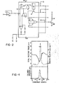
- the signal conditioning circuitry 20 may be of many different types and one example of such circuitry is shown in detail in Figure 2.
- the signal conditioning circuitry 20 includes a first amplifier 21 which acts as a buffer to isolate signals from the sensor 18 and the remaining signal conditioning circuitry.
- the output from the first amplifier 21 is input to an adaptive sensing amplifier 22 which converts the pulse output from the amplifier 21 into a rectangular wave signal.
- the adaptive sense amplifier 22 may be any conventional sense amplifier such as the one sold commercially by National SemiConductor, Inc., under model number LM1815.
- the output from the sense amplifier 22 is input to the base electrode of a transistor 24 which acts as a buffer.
- a second measuring means 26 is also mounted on the engine 12 for measuring the gas pressure in one cylinder of the engine 12.
- the second measuring means or sensor 26 is a pressure transducer, such as a quartz pressure transducer model number AVL 8QP500C.
- the output from the sensor 26 is input through an amplifier 28 to a central processing unit 30.
- the amplifier 28 is a dual mode amplifier type number 504E.
- the output from the amplifier 28 is input through an analog-digital converter 29.
- the analog/digital , converter can be any suitable type of A/D converter, such as model number AD571 sold by Analog Devices, Inc.
- the central processing unit 30 may be any type of computer based device; however, a microprocessor, such as one sold by Intel Corporation under model number 8086 or model number 6502 sold by Rockwell International is preferred.
- the central processing unit 30 receives as inputs the outputs from the A/D converter 29 and signal conditioning circuitry 20 and communicates with a memory 32, a timer/counter 34 and a clock 36.
- the central processing unit 30 outputs to an indicator 38 the total instantaneous frictional torque of the engine 12 during any time in the engine operating cycle as describer hereafter.
- the memory 32 is of the random access type to enable the central processing unit 32 to selectively store data therein accumulated from the first and second sensors 18 and 26, respectively, during the engine operating cycle. Such data can then be operated on by the central processing unit 30 to calculate the total instantaneous frictional torque.
- the counter 34 receives output signals from the central processing unit 30 which correspond to a signal from the sensor 18 indicative of the completion of a pre-determined amount of angular rotation of the engine 12, as exemplified by the passage of one gear tooth of the flywheel 16 past the sensor 18.
- the counter 34 then counts clock pulses from the clock 36 at the clock frequency.
- the frequency of the clock 36 is selected with regard to the rotational speed of the engine 12 and typically could range between 0.5MHz and 20MHz.
- the indicator 38 may be any type of indicator which provides a visual display of the total instantaneous frictional torque calculated by the central processing unit 30.
- a conventional printer, CRT display or oscilloscope may be utilized to provide a ready indication of the total instantaneous frictional torque during the operating cycle of the engine 12.
- the central processing unit 30 executes a program stored in the memory 32. With the engine 12 operating at zero load, i.e., idling, the central processing unit 30 executes the first stored program and initializes the interrupt routine and counter.
- the central processing unit 30 is initially programmed for a predetermined number of samples. For example, if the flywheel 16 has 138 gear teeth and the engine 12 is of the four stroke type requiring two revolutions to complete one engine cycle, the central processing unit 30 may be programmed to detect pulses over seven complete engine cycles for a total of 1932 separate signals. However, any sample size may be employed.
- the central processing unit 30 is interrupt driven, that is, processing of data will take place upon detecting an interrupt generated by a signal from the sensor 18 indicating the passage of one gear tooth of the flywheel 16 past the sensor 18 and corresponds to a certain amount of rotation of the engine 12.
- the central processing unit 30 Upon receiving a first signal from the sensor 18, the central processing unit 30 will go into an interrupt mode and enable the counter 34 to count pulses from the clock 36. Upon the occurrence of the next signal from the sensor 18. This signal indicates the completion of a pre-determined amount of engine rotation as evidenced by the passage of the next gear tooth of the flywheel 16 past the sensor 18, the central processing unit 30 will process the stored count information. When the next signal is received from the sensor 18, the stored count information is transferred to an internal holding register in the counter 34 and the counter 34 is re-enabled for counting subsequent clock pulses.
- the data stored in the counter 34 corresponding to the number of counted clock pulses during one pre- determined period of the engine rotation, is related to the x(k) or the transition time between two consecutive gear teeth on the flywheel 16.
- the central processing unit 30 reads the data in the holding register in the counter 34 and stores the data in the memory 32. At the completion of the total number of engine cycles, the central processing unit 30 will disable the interrupt and begin processing the stored data.
- the stored time sequence signals correspond to the instantaneous angular velocity of the engine 12. Variations in the time signals correspond to variations in the instantaneous angular velocity of the engine 12.
- the output of the A/D converter 29 is read by the central processing unit 30 while in the interrupt mode.
- the output of the A/D converter 29 corresponds to the cylinder pressure at the time the interrupt takes place.
- the central processing unit stores this value in the memory 32.
- the stored data for the cylinder pressure and to the time periods between the passage of consecutive gear teeth on the flywheel / 16 past the first sensor 18 is analyzed.
- the program executed by the central processing unit 30 calculates the total frictional torque according to the following equation:
- the total instantaneous friction torque can be described as a function of the gas pressure, the instantaneous angular velocity of the engine and the engine design and the operating parameters by the following equation: where:
Landscapes
- Engineering & Computer Science (AREA)
- Physics & Mathematics (AREA)
- General Physics & Mathematics (AREA)
- Chemical & Material Sciences (AREA)
- Combustion & Propulsion (AREA)
- Mechanical Engineering (AREA)
- General Engineering & Computer Science (AREA)
- Testing Of Engines (AREA)
- Combined Controls Of Internal Combustion Engines (AREA)
- Force Measurement Appropriate To Specific Purposes (AREA)
Abstract
Description
- This invention relates, in general, to engine testing apparatus and methods for determining the operating characteristics of an engine and, more specifically, to apparatus and methods for determining the total instantaneous friction in a reciprocating internal combustion engine.
- - In an internal combustion engine, such as a gasoline or diesel or other fuel powered, reciprocating, internal combustion engine, friction between the various reciprocating and rotating components of the engine as well as various accessories mounted on the engine must be minimized if the engine is to run efficiently and at maximum power/fuel usage levels. Engine friction is present in the reciprocating and rotating components of an engine, such as the assembly valve train, auxiliary accessories and bearings. All of these components contribute to a total friction loss which detracts from the work output of the engine and causes wear on the engine components over long term use.
- Such frictional losses are also subtracted directly from the net work done by the gases on the pistons during the thermodynamic engine cycle. Accordingly, any reduction in such frictional losses results in a direct gain in the brake thermal efficiency of the engine.
- Many different techniques have been used to measure the power, torque or mean effective pressure required to overcome the total frictional losses within a reciprocating internal combustion engine. All of these approaches, however, provide different degrees of accuracy and all provide mean average values over the entire engine cycle or an indication of the overall frictional losses without any reflection on the instantaneous friction at any instant during the engine cycle. The engine in the total instantaneous friction torque cannot be determined by such previously devised methods. An indication of the total instantaneous friction torque of the engine would be beneficial to an engine designer as the designer could devote his efforts to reducing friction in those areas which would be most effective in improving the fuel economy of the engine.
- Thus, it would be desirable to provide an apparatus and method for measuring the total instantaneous friction torque caused by the various components in the reciprocating internal combustion engine. It would also be desirable to provide an apparatus and method for measuring the total instantaneous frictional torque which is useful as a design tool to minimize the frictional losses caused by the various moving parts of a reciprocating internal combustion engine.
- The present invention is an apparatus and method for measuring the total instantaneous friction torque in reciprocating internal combustion engines.
- The apparatus includes a central processing unit which receives inputs from two sensors mounted on a reciprocating internal combustion engine. The first sensor is mounted in close association with a rotating component of the engine such as the flywheel, crankshaft, and/or camshaft. The first sensor generates an electrical signal upon the start of one period of rotation of the engine and a second signal which indicates completion of a pre-determined period of rotation of the engine. A time signal is generated which corresponds to the time required for the engine to rotate through a pre-determined amount of angular rotation. In a preferred embodiment, the first sensor is mounted adjacent to the flywheel of the engine and detects the amount of time required for the engine to rotate between successive gear teeth on the flywheel.
- The second sensor is also mounted on the engine and provides an output signal corresponding to the gas pressure within the cylinder(s) of the engine. The output from both of the first and second sensors, after suitable signal processing, are input to the central processor which stores the measured values in a memory.
- A second stored program is also executed by the central processing unit to calculate the total instantaneous friction of the engine during the timed cycle. The second stored program executes and solves the equation:
TF = Ta - TIN(rec)- TIN(rot)- TL
which computes the instantaneous gas torque Ta at different crank angle degrees from the gas pressure, piston area, crank radius and length of the connecting rods of the engine. The reciprocating and rotating inertia torques are computed from the corresponding masses and the instantaneous acceleration of these masses. The instantaneous acceleration of these masses is calculated from the measured instantaneous angular velocity of the crank shaft. The load instantaneous torque due to the load on the engine can also be obtained from the characteristics of the load or can be measured by a torque meter mounted between the flywheel and the load, the torque due to the load is equal to zero when the engine is idling. Solution of this equation . generates output data which provides a direct indication of the total instantaneous frictional torque of the engine. Since it is known that various components generate greater frictional losses at certain times during the crank/cycle of the engine, the shape and/or values of the total instantaneous friction torque provide extremely useful data to an engine designer and enables the designer to devote his efforts to reducing friction and its resulting losses in those areas which contribute most to the total frictional losses within an engine. Also, the total instantaneous friction torque can be a very effective tool to the lubrication engineer or scientist in developing lubricating oils and additives which reduce engine friction. - The various features, advantages and other uses of the present invention will become more apparent by referring to the following detailed description and drawing in which:
- Figure 1 is a block diagram of the instantaneous friction indicator apparatus of the present invention;
- Figure 2 is a circuit diagram of the signal conditioning circuitry shown in Figure 1;
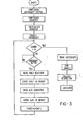
- Figure 3 is a flow chart illustrating the operation of one portion of the stored program in the central processing unit of the apparatus of the present invention; and
- Figure 4 is a graph illustrating the output from the friction indicating apparatus of the present invention.
- Throughout the following description and drawing, an identical reference number is used to refer to the same component shown in multiple figures of the drawing.
- The present invention is an apparatus and method for calculating the total instantaneous frictional torque of an - operating, reciprocating internal combustion engine. The apparatus and method of the present invention is useful as a research and design tool in that it enables a designer to obtain a quantitative indication of the instantaneous.friction torque at all instances during the cycle of a reciprocating internal combustion engine. When such total instantaneous frictional torques have been determined, the engine designer or lubrication engineer can direct his efforts to those areas or components which contribute most to reduced engine efficiency thereby resulting in a more efficient engine design or a better lubri-- cating oil or oil additive.
- Referring now to Figure 1, there is illustrated an
apparatus 10 for calculating the total instantaneous frictional torque of an operating, reciprocating internal combustion engine. Theapparatus 10 is usable with any reciprocating,internal combustion engine 12, such as those powered by gasoline or diesel fuels or any other liquid, solid or gaseous fuel. Theengine 12 may be either single or multiple cylinder constructed of n four-stroke-cycle or two-stroke-cycle type. As is conventional, such internal combustion engines include a rotating member such as acrank shaft 14 which rotates a predetermined number of rotations per engine cycle. In addition to thecrank shaft 14, other rotatable components of theengine 12 may include a cam shaft, not shown, and a flywheel 16 mounted on the end of thecrank shaft 14. - The
apparatus 10 of the present invention includes means 18 for measuring the instantaneous angular velocity of theengine 12. - The measuring means 18 preferably is a sensor which is mounted on the
engine 12 in close proximity to one of the rotating components of theengine 12, such as the flywheel 16, thecrankshaft 14 or the camshaft. As illustrated in Figure 1, by way of example only, thesensor 18 is mounted in close proximity with the flywheel 16 and detects the passage of each gear tooth of the flywheel ring gear as the flywheel 16 rotates past thesensor 18. Alternately, the-sensor 18 could be mounted on or adjacent to thecrankshaft 14 or the camshaft to detect pre-determined amounts of angular rotation of these components of theengine 12. - In one embodiment, the
sensor 18 may be a magnetic pick-up or a photo-electric cell which is mounted on theengine 12 adjacent to the flywheel 16. Thesensor 18 detects the passage of each gear tooth of the flywheel ring gear therepast and generates a signal as each gear tooth passes the pick-up 18. Alternately, in place of a magnetic pick-up or photo-cell thesensor 18 may be an encoder which generates an output signal upon the occurrence of a pre-determined amount of angular rotation of theengine 12. - The output from the
sensor 18 is input to signal conditioning circuitry, denoted in general byreference number 20 in Figure 1. Thesignal conditioning circuitry 20 may be of many different types and one example of such circuitry is shown in detail in Figure 2. - The
signal conditioning circuitry 20 includes a first amplifier 21 which acts as a buffer to isolate signals from thesensor 18 and the remaining signal conditioning circuitry. The output from the first amplifier 21 is input to an adaptive sensing amplifier 22 which converts the pulse output from the amplifier 21 into a rectangular wave signal. The adaptive sense amplifier 22 may be any conventional sense amplifier such as the one sold commercially by National SemiConductor, Inc., under model number LM1815. The output from the sense amplifier 22 is input to the base electrode of a transistor 24 which acts as a buffer. - A second measuring means 26 is also mounted on the
engine 12 for measuring the gas pressure in one cylinder of theengine 12. Preferably the second measuring means orsensor 26 is a pressure transducer, such as a quartz pressure transducer model number AVL 8QP500C. The output from thesensor 26 is input through anamplifier 28 to acentral processing unit 30. In the preferred embodiment, theamplifier 28 is a dual mode amplifier type number 504E. - The output from the
amplifier 28 is input through an analog-digital converter 29. The analog/digital , converter can be any suitable type of A/D converter, such as model number AD571 sold by Analog Devices, Inc. - The
central processing unit 30 may be any type of computer based device; however, a microprocessor, such as one sold by Intel Corporation under model number 8086 or model number 6502 sold by Rockwell International is preferred. Thecentral processing unit 30 receives as inputs the outputs from the A/D converter 29 andsignal conditioning circuitry 20 and communicates with amemory 32, a timer/counter 34 and aclock 36. Thecentral processing unit 30 outputs to anindicator 38 the total instantaneous frictional torque of theengine 12 during any time in the engine operating cycle as describer hereafter. - The
memory 32 is of the random access type to enable thecentral processing unit 32 to selectively store data therein accumulated from the first andsecond sensors central processing unit 30 to calculate the total instantaneous frictional torque. - The
counter 34 receives output signals from thecentral processing unit 30 which correspond to a signal from thesensor 18 indicative of the completion of a pre-determined amount of angular rotation of theengine 12, as exemplified by the passage of one gear tooth of the flywheel 16 past thesensor 18. Thecounter 34 then counts clock pulses from theclock 36 at the clock frequency. In the preferred embodiment, the frequency of theclock 36 is selected with regard to the rotational speed of theengine 12 and typically could range between 0.5MHz and 20MHz. - The
indicator 38 may be any type of indicator which provides a visual display of the total instantaneous frictional torque calculated by thecentral processing unit 30. Thus, a conventional printer, CRT display or oscilloscope may be utilized to provide a ready indication of the total instantaneous frictional torque during the operating cycle of theengine 12. - The operation of the
apparatus 10 of the present invention in calculating the total instantaneous frictional torque of theengine 12 will now be explained in conjunction with Figures 3 and 4. It will be understood that other configurations may also be employed. - In calculating the total instantaneous frictional torque, the
central processing unit 30 executes a program stored in thememory 32. With theengine 12 operating at zero load, i.e., idling, thecentral processing unit 30 executes the first stored program and initializes the interrupt routine and counter. Thecentral processing unit 30 is initially programmed for a predetermined number of samples. For example, if the flywheel 16 has 138 gear teeth and theengine 12 is of the four stroke type requiring two revolutions to complete one engine cycle, thecentral processing unit 30 may be programmed to detect pulses over seven complete engine cycles for a total of 1932 separate signals. However, any sample size may be employed. - The
central processing unit 30 is interrupt driven, that is, processing of data will take place upon detecting an interrupt generated by a signal from thesensor 18 indicating the passage of one gear tooth of the flywheel 16 past thesensor 18 and corresponds to a certain amount of rotation of theengine 12. - Upon receiving a first signal from the
sensor 18, thecentral processing unit 30 will go into an interrupt mode and enable thecounter 34 to count pulses from theclock 36. Upon the occurrence of the next signal from thesensor 18. This signal indicates the completion of a pre-determined amount of engine rotation as evidenced by the passage of the next gear tooth of the flywheel 16 past thesensor 18, thecentral processing unit 30 will process the stored count information. When the next signal is received from thesensor 18, the stored count information is transferred to an internal holding register in thecounter 34 and thecounter 34 is re-enabled for counting subsequent clock pulses. - The data stored in the
counter 34, corresponding to the number of counted clock pulses during one pre- determined period of the engine rotation, is related to the x(k) or the transition time between two consecutive gear teeth on the flywheel 16. Thecentral processing unit 30 reads the data in the holding register in thecounter 34 and stores the data in thememory 32. At the completion of the total number of engine cycles, thecentral processing unit 30 will disable the interrupt and begin processing the stored data. - The stored time sequence signals correspond to the instantaneous angular velocity of the
engine 12. Variations in the time signals correspond to variations in the instantaneous angular velocity of theengine 12. - The output of the A/
D converter 29 is read by thecentral processing unit 30 while in the interrupt mode. The output of the A/D converter 29 corresponds to the cylinder pressure at the time the interrupt takes place. The central processing unit stores this value in thememory 32. - Upon completion of the pre-programmed number of engine cycles, the stored data for the cylinder pressure and to the time periods between the passage of consecutive gear teeth on the flywheel/16 past the
first sensor 18 is analyzed. - The program executed by the
central processing unit 30 calculates the total frictional torque according to the following equation:
- TF = Total Instantaneous Frictional Torque
- TG = Torque due to the gas pressure PG.
- TIN(rec) = Torque of Reciprocating Engine Components
- TIN(rot) = Torque of Rotating Engine Components
- TL = Load Torque on the Engine (is equal to zero when the engine is idling).
- The total instantaneous friction torque can be described as a function of the gas pressure, the instantaneous angular velocity of the engine and the engine design and the operating parameters by the following equation:

- r,ℓ = obtained from the engine geometry
- I = calculated from the geometry and masses of rotating parts which consist of the flywheel, crankshaft, and part of the connecting rod.
- Fgas = calculated from the measured gas pressure PG and piston area.
- m = mass of the reciprocating parts which consist of the piston assembly and the reciprocating part of the connecting rod.
- g = gravitational acceleration.
- FIN = inertia force of the reciprocating Darts calculated from

- TL = is the load torque. Typically all L calculations are made at no load where TL = O.
- The output of the latter equation for the total instantaneous frictional torque of the
engine 12 is displayed and/or recorded in theindicator 38, as shown in Figure 4 along with the instantaneous gas pressure and the instantaneous angular velocity of theengine 12. - In order to clarify the method employed by the apparatus of the present invention in calculating the total instantaneous frictional torque in a reciprocating internal combustion engine, the following steps are performed:
- 1. measuring the gas pressure within the engine (p);
- 2. measuring the instantaneous angular velocity of the engine (ω); and
- 3. calculating the total instantaneous frictional torque according to the equation:
- The solution of the equation is then outputted to the
indicator 38. In this manner, a unique indication of the total instantaneous frictional torque in an operating, reciprocating internal combustion engine is obtained under the (P -ω) method described above. This provides invaluable data to an engine designer which will enable him to concentrate his efforts on those frictional loss components which most adversely effect engine efficiency. Also the total instantaneous frictional torque enables the lubrication engineer to develop lubricating oils and additives which reduce friction and wear in engines. - Additional information regarding the calculation of the total instantaneous friction torque in an engine can be had by referring to a Society of Automotive Engineering technical paper number 840179 entitled "A New Approach to Evaluate the Instantaneous Friction and its Internal Components in Internal Combustion Engines", authored by Sohair F. Rezaka and Naeim A. Henein, Wayne State University, Detroit, Michigan, the contents of which are incorporated herein by reference.

Claims (5)
the first detecting means detects the passage of each flywheel gear teeth past the first detecting means.
Applications Claiming Priority (2)
| Application Number | Priority Date | Filing Date | Title |
|---|---|---|---|
| US70438185A | 1985-02-22 | 1985-02-22 | |
| US704381 | 1985-02-22 |
Publications (2)
| Publication Number | Publication Date |
|---|---|
| EP0199431A2 true EP0199431A2 (en) | 1986-10-29 |
| EP0199431A3 EP0199431A3 (en) | 1988-08-31 |
Family
ID=24829241
Family Applications (1)
| Application Number | Title | Priority Date | Filing Date |
|---|---|---|---|
| EP86301184A Withdrawn EP0199431A3 (en) | 1985-02-22 | 1986-02-20 | Instantaneous friction indicator for reciprocating internal combustion engines and method for calculating instantaneous friction |
Country Status (3)
| Country | Link |
|---|---|
| EP (1) | EP0199431A3 (en) |
| JP (1) | JPS61201136A (en) |
| CA (1) | CA1242278A (en) |
Cited By (11)
| Publication number | Priority date | Publication date | Assignee | Title |
|---|---|---|---|---|
| DE3743066A1 (en) * | 1987-12-18 | 1989-06-29 | Asea Brown Boveri | METHOD FOR DETERMINING THE MEDIUM ACTION TORQUE OF AN INTERNAL COMBUSTION ENGINE |
| EP0559112A2 (en) * | 1992-03-03 | 1993-09-08 | Klaus Dipl.-Ing. Nowak | Procedure and device for measuring the power of piston combustion engines |
| EP0615117A2 (en) * | 1993-03-08 | 1994-09-14 | Yamaha Hatsudoki Kabushiki Kaisha | Engine torque-detecting method and an apparatus therefor |
| US5656768A (en) * | 1994-09-30 | 1997-08-12 | Avl Gesellschaft Fur Verbrennungskraftmaschinen Und Messtechnik M.B.H. Prof. Dr.H.C. Hans List | Method for determining the moment of inertia |
| US5715794A (en) * | 1995-05-12 | 1998-02-10 | Yamaha Hatsudoki Kabushiki Kaisha | Engine control system and method |
| US5738074A (en) * | 1995-10-02 | 1998-04-14 | Yamaha Hatsudoki Kabushiki Kaisha | Engine control system and method |
| WO1999007072A1 (en) * | 1997-08-01 | 1999-02-11 | Siemens Aktiengesellschaft | Trigger level adjustment process and device, and digital storage oscilloscope equipped with such a device |
| EP0985919A1 (en) * | 1998-09-10 | 2000-03-15 | MAGNETI MARELLI S.p.A. | Method for determining the progression of the load torque in an internal-combustion engine |
| WO2004048762A1 (en) * | 2002-11-27 | 2004-06-10 | Ricardo Consulting Engineers Limited | Improved engine management |
| US7117080B2 (en) | 2001-06-13 | 2006-10-03 | Abb Ab | Method to determine TDC in an internal combustion engine |
| FR2950970A3 (en) * | 2009-10-05 | 2011-04-08 | Renault Sa | Method for estimating average gas target produced by combustion in e.g. petrol engine of motor vehicle, involves deducing balancing coefficients from calculated average value and estimated average torque value based on linear combination |
-
1986
- 1986-02-20 EP EP86301184A patent/EP0199431A3/en not_active Withdrawn
- 1986-02-21 JP JP61035422A patent/JPS61201136A/en active Pending
- 1986-02-21 CA CA000502461A patent/CA1242278A/en not_active Expired
Non-Patent Citations (2)
| Title |
|---|
| IEEE TRANSACTIONS ON INDUSTRIAL ELECTRONICS, vol. IE-30, no. 2, May 1983, pages 159-163, IEEE, New York, US; A.K. SOOD et al.: "A real-time microprocessor-based system for engine deficiency analysis" * |
| SOCIETY OF AUTOMOTIVE ENGINEERS, INC, paper 840179, February 1984, pages 1932-1943; S.F. REZEKA et al.: "A new approach to evaluate instantaneous friction and, its components in internal combustion engines" * |
Cited By (16)
| Publication number | Priority date | Publication date | Assignee | Title |
|---|---|---|---|---|
| DE3743066A1 (en) * | 1987-12-18 | 1989-06-29 | Asea Brown Boveri | METHOD FOR DETERMINING THE MEDIUM ACTION TORQUE OF AN INTERNAL COMBUSTION ENGINE |
| EP0559112A2 (en) * | 1992-03-03 | 1993-09-08 | Klaus Dipl.-Ing. Nowak | Procedure and device for measuring the power of piston combustion engines |
| EP0559112A3 (en) * | 1992-03-03 | 1993-11-10 | Nowak Klaus | Procedure and device for measuring the power of piston combustion engines |
| US6332352B1 (en) | 1993-03-08 | 2001-12-25 | Yamaha Hatsudoki Kabushiki Kaisha | Engine torque-detecting method and an apparatus therefor |
| EP0615117A2 (en) * | 1993-03-08 | 1994-09-14 | Yamaha Hatsudoki Kabushiki Kaisha | Engine torque-detecting method and an apparatus therefor |
| EP0615117A3 (en) * | 1993-03-08 | 1995-01-11 | Yamaha Motor Co Ltd | Engine torque-detecting method and an apparatus therefor. |
| US5656768A (en) * | 1994-09-30 | 1997-08-12 | Avl Gesellschaft Fur Verbrennungskraftmaschinen Und Messtechnik M.B.H. Prof. Dr.H.C. Hans List | Method for determining the moment of inertia |
| US5715794A (en) * | 1995-05-12 | 1998-02-10 | Yamaha Hatsudoki Kabushiki Kaisha | Engine control system and method |
| US5738074A (en) * | 1995-10-02 | 1998-04-14 | Yamaha Hatsudoki Kabushiki Kaisha | Engine control system and method |
| WO1999007072A1 (en) * | 1997-08-01 | 1999-02-11 | Siemens Aktiengesellschaft | Trigger level adjustment process and device, and digital storage oscilloscope equipped with such a device |
| EP0985919A1 (en) * | 1998-09-10 | 2000-03-15 | MAGNETI MARELLI S.p.A. | Method for determining the progression of the load torque in an internal-combustion engine |
| US6354149B1 (en) | 1998-09-10 | 2002-03-12 | Magneti Marelli Spa | Method for determining the progression of the load torque in an internal-combustion engine |
| US7117080B2 (en) | 2001-06-13 | 2006-10-03 | Abb Ab | Method to determine TDC in an internal combustion engine |
| WO2004048762A1 (en) * | 2002-11-27 | 2004-06-10 | Ricardo Consulting Engineers Limited | Improved engine management |
| US7506536B2 (en) | 2002-11-27 | 2009-03-24 | Ricardo Uk Limited | Method of deriving engine cylinder mechanical top dead centre |
| FR2950970A3 (en) * | 2009-10-05 | 2011-04-08 | Renault Sa | Method for estimating average gas target produced by combustion in e.g. petrol engine of motor vehicle, involves deducing balancing coefficients from calculated average value and estimated average torque value based on linear combination |
Also Published As
| Publication number | Publication date |
|---|---|
| EP0199431A3 (en) | 1988-08-31 |
| JPS61201136A (en) | 1986-09-05 |
| CA1242278A (en) | 1988-09-20 |
Similar Documents
| Publication | Publication Date | Title |
|---|---|---|
| US4292670A (en) | Diagnosis of engine power and compression balance | |
| EP0184536B1 (en) | Absolute compression test | |
| CA1222317A (en) | Method of determining engine cylinder compression pressure and power output | |
| US3972230A (en) | Detecting malfunction in cylinders of internal combustion engines | |
| EP0199431A2 (en) | Instantaneous friction indicator for reciprocating internal combustion engines and method for calculating instantaneous friction | |
| US4358828A (en) | Engine speed measuring system | |
| JPH01240754A (en) | Method and device for measuring engine air flow | |
| US4348893A (en) | Relative compression of an asymmetric internal combustion engine | |
| US4055993A (en) | Sub-cyclic measurement of speed of an internal combustion engine | |
| JPH04232828A (en) | Cylinder-performance analyzing method for internal combustion engine | |
| EP1221029A1 (en) | Measuring twist due to torque in a rotating shaft | |
| CA1222316A (en) | Engine deficiency indicator | |
| US4520658A (en) | Method of locating engine top dead center position | |
| US4707791A (en) | On-board motor vehicle timing measurement system | |
| US5503009A (en) | Method for recognizing irregular combustions in a cylinder of an internal combustion engine | |
| Mauer et al. | On-line cylinder diagnostics on combustion engines by noncontact torque and speed measurements | |
| US4453402A (en) | Method and apparatus for determining the position of a piston in the cylinder of a reciprocating engine | |
| KR830001928B1 (en) | Device for continuously detecting the engine's instantaneous speed | |
| JPH0345332B2 (en) | ||
| JPS6410768B2 (en) | ||
| JP2559516B2 (en) | Combustion state detection device for internal combustion engine | |
| JP3011353B2 (en) | Measuring method of rotation fluctuation rate of multi-cylinder engine | |
| House et al. | Arequest for correction of errors in pages 6 to 13 of the© Applicant: WAYNE STATE UNIVERSITY description has been filed pursuant to Rule 88 EPC. 100 Antoinette Detroit Michigan 48202 (US)© Priority: 22.02. 85 US 704381© Inventor: Rezaka, Sohair F. | |
| RU2061208C1 (en) | Method of check of working process of diesel engine | |
| JPH0522065B2 (en) |
Legal Events
| Date | Code | Title | Description |
|---|---|---|---|
| PUAI | Public reference made under article 153(3) epc to a published international application that has entered the european phase |
Free format text: ORIGINAL CODE: 0009012 |
|
| AK | Designated contracting states |
Kind code of ref document: A2 Designated state(s): AT BE CH DE FR GB IT LI LU NL SE |
|
| PUAL | Search report despatched |
Free format text: ORIGINAL CODE: 0009013 |
|
| AK | Designated contracting states |
Kind code of ref document: A3 Designated state(s): AT BE CH DE FR GB IT LI LU NL SE |
|
| STAA | Information on the status of an ep patent application or granted ep patent |
Free format text: STATUS: THE APPLICATION IS DEEMED TO BE WITHDRAWN |
|
| 18D | Application deemed to be withdrawn |
Effective date: 19890301 |
|
| RIN1 | Information on inventor provided before grant (corrected) |
Inventor name: HENEIN, NAEIM A. Inventor name: REZAKA, SOHAIR F. |