EP0058519A2 - Elektrische Verbindung hoher Leitfähigkeit für einen Schalter oder andere elektrische Apparate - Google Patents
Elektrische Verbindung hoher Leitfähigkeit für einen Schalter oder andere elektrische Apparate Download PDFInfo
- Publication number
- EP0058519A2 EP0058519A2 EP82300674A EP82300674A EP0058519A2 EP 0058519 A2 EP0058519 A2 EP 0058519A2 EP 82300674 A EP82300674 A EP 82300674A EP 82300674 A EP82300674 A EP 82300674A EP 0058519 A2 EP0058519 A2 EP 0058519A2
- Authority
- EP
- European Patent Office
- Prior art keywords
- stem
- circuit interrupter
- conductor
- terminal
- compression
- Prior art date
- Legal status (The legal status is an assumption and is not a legal conclusion. Google has not performed a legal analysis and makes no representation as to the accuracy of the status listed.)
- Granted
Links
- 239000004020 conductor Substances 0.000 claims abstract description 87
- 230000006835 compression Effects 0.000 claims description 32
- 238000007906 compression Methods 0.000 claims description 32
- 229910052751 metal Inorganic materials 0.000 claims description 8
- 239000002184 metal Substances 0.000 claims description 8
- 125000006850 spacer group Chemical group 0.000 claims description 7
- 239000000463 material Substances 0.000 claims description 6
- 230000002093 peripheral effect Effects 0.000 claims description 4
- 230000015572 biosynthetic process Effects 0.000 claims description 2
- 238000010276 construction Methods 0.000 description 7
- RYGMFSIKBFXOCR-UHFFFAOYSA-N Copper Chemical compound [Cu] RYGMFSIKBFXOCR-UHFFFAOYSA-N 0.000 description 6
- 239000012212 insulator Substances 0.000 description 6
- 230000000712 assembly Effects 0.000 description 5
- 238000000429 assembly Methods 0.000 description 5
- 229910052802 copper Inorganic materials 0.000 description 5
- 239000010949 copper Substances 0.000 description 5
- 229910052782 aluminium Inorganic materials 0.000 description 4
- XAGFODPZIPBFFR-UHFFFAOYSA-N aluminium Chemical compound [Al] XAGFODPZIPBFFR-UHFFFAOYSA-N 0.000 description 4
- 230000000295 complement effect Effects 0.000 description 3
- 230000000630 rising effect Effects 0.000 description 3
- 230000017525 heat dissipation Effects 0.000 description 2
- 238000000034 method Methods 0.000 description 2
- 229910000831 Steel Inorganic materials 0.000 description 1
- 230000004888 barrier function Effects 0.000 description 1
- 230000005465 channeling Effects 0.000 description 1
- 238000009434 installation Methods 0.000 description 1
- 238000009413 insulation Methods 0.000 description 1
- 238000004519 manufacturing process Methods 0.000 description 1
- 238000009877 rendering Methods 0.000 description 1
- 230000000717 retained effect Effects 0.000 description 1
- 239000010959 steel Substances 0.000 description 1
Images


Classifications
-
- H—ELECTRICITY
- H01—ELECTRIC ELEMENTS
- H01H—ELECTRIC SWITCHES; RELAYS; SELECTORS; EMERGENCY PROTECTIVE DEVICES
- H01H33/00—High-tension or heavy-current switches with arc-extinguishing or arc-preventing means
- H01H33/60—Switches wherein the means for extinguishing or preventing the arc do not include separate means for obtaining or increasing flow of arc-extinguishing fluid
- H01H33/66—Vacuum switches
- H01H33/6606—Terminal arrangements
-
- H—ELECTRICITY
- H01—ELECTRIC ELEMENTS
- H01R—ELECTRICALLY-CONDUCTIVE CONNECTIONS; STRUCTURAL ASSOCIATIONS OF A PLURALITY OF MUTUALLY-INSULATED ELECTRICAL CONNECTING ELEMENTS; COUPLING DEVICES; CURRENT COLLECTORS
- H01R35/00—Flexible or turnable line connectors, i.e. the rotation angle being limited
-
- H—ELECTRICITY
- H02—GENERATION; CONVERSION OR DISTRIBUTION OF ELECTRIC POWER
- H02B—BOARDS, SUBSTATIONS OR SWITCHING ARRANGEMENTS FOR THE SUPPLY OR DISTRIBUTION OF ELECTRIC POWER
- H02B11/00—Switchgear having carriage withdrawable for isolation
- H02B11/02—Details
- H02B11/04—Isolating-contacts, e.g. mountings or shieldings
-
- H—ELECTRICITY
- H01—ELECTRIC ELEMENTS
- H01H—ELECTRIC SWITCHES; RELAYS; SELECTORS; EMERGENCY PROTECTIVE DEVICES
- H01H1/00—Contacts
- H01H1/58—Electric connections to or between contacts; Terminals
- H01H1/5822—Flexible connections between movable contact and terminal
-
- H—ELECTRICITY
- H01—ELECTRIC ELEMENTS
- H01H—ELECTRIC SWITCHES; RELAYS; SELECTORS; EMERGENCY PROTECTIVE DEVICES
- H01H1/00—Contacts
- H01H1/58—Electric connections to or between contacts; Terminals
- H01H1/5822—Flexible connections between movable contact and terminal
- H01H2001/5827—Laminated connections, i.e. the flexible conductor is composed of a plurality of thin flexible conducting layers
-
- H—ELECTRICITY
- H01—ELECTRIC ELEMENTS
- H01H—ELECTRIC SWITCHES; RELAYS; SELECTORS; EMERGENCY PROTECTIVE DEVICES
- H01H33/00—High-tension or heavy-current switches with arc-extinguishing or arc-preventing means
- H01H33/60—Switches wherein the means for extinguishing or preventing the arc do not include separate means for obtaining or increasing flow of arc-extinguishing fluid
- H01H33/66—Vacuum switches
- H01H33/6606—Terminal arrangements
- H01H2033/6613—Cooling arrangements directly associated with the terminal arrangements
Definitions
- This invention relates to electrical interconnection apparatus and more particularly to apparatus for interconnecting a circular stem with a relatively flat electrical conductor, or a stationary terminal.
- Circuit breaker apparatus in general and vacuum circuit interrupter apparatus are useful for controlling and protecting electrical systems, apparatus and networks.
- Circuit breaker apparatus and in particular vacuum circuit interrupter apparatus include separable main contacts disposed within an insulating housing. Generally one of the contacts is fixed relative to both the housing and to an external electrical conductor which is interconnected with the circuit to be controlled by the circuit interrupter.
- the other separable main contact is movable.
- the movable contact assembly usually comprises a stem of circular cross section having the contact at one end thereof enclosed within the vacuum chamber and a driving mechanism at the other end thereof external to the vacuum chamber.
- a flexible gas-tight bellows separates the vacuum chamber from the external region.
- the bellow expands and contracts with the movement of the stem so as to allow stem movement while at the same time retaining the integrity of the vacuum. It has been found that the circular shape of the stem is desirable for interconnection with the bellows among other things. Often the electrical interconnection between the aforementioned external apparatus or circuit to be protected by the circuit interrupter and the movable contact is made on the circular stem. It can be seen therefore that a need arises for channeling significant amounts of electrical current from a movable stem to a stationary electrical terminal or contact.
- a flexible conductor such as braided copper. wire or the like. Examples of this may be found in the specification of U.S. Patent Nos.
- a circuit interrupter system comprising circuit interrupter means including separable contacts one of which is interconnected with an external terminal, where said terminal is a stem having a predetermined cross sectional shape, an external conductor connected to said external stem, said conductor having a substantially flat planar portion with an opening therein which is of the same cross-sectional shape as said stem but slightly smaller in cross sectional area, said periphery of said opening having a slit therein which provides a peripheral tab which is offset from the plane of said flat planar surface when said opening is initially disposed around said stem to thus initially accommodate for the difference in area; and compression means cooperating with said external conductor means and said terminal to cause the material of said conductor to flow in the region of said interface between said external conductor means and said terminal when the force of compression is applied with a substantial component normal to the plane of flow.
- the electrical apparatus includes an axial stem where the stem is generally circular in cross-section.
- a conductor is connected to the stem.
- the conductor is a generally flat inner portion with a central circular opening therein.
- the central opening has a smaller radius than the radius of the cross-section of the stem.
- the periphery of the'central opening has a radial slit therein that allows the formation of the peripheral tab which is offset from the plane of the flat planar surface when the opening is initially disposed around the stem to thus initially accommodate for the difference in radii.
- Compression apparatus is disposed on the stem in a disposition of axial compression for causing the aforementioned tab to substantially realign with the plane of the planar portion after compression.
- the material of the tab thus assuming a flowed state in the region of the interface between the tab and the stem after compression to accommodate in the difference in radii.
- Multiple conductors are provided for reduced contact resistance relative to a given surface area and current capability of each conductor.
- a movable electrical terminal which is movable in a given direction in relationship to a desired electrical terminal arid an electrically conducting member which is fixedly attached to both the movable electrical terminal and the fixed electrical terminal to interconnect both electrically.
- the electrically conducting member is characterized as being substantially self-supporting in a span between the movable electrical terminal and the fixed. electrical terminal, but nevertheless is flexible enough in a cantilevered manner for accommodating the movement of the movable electrical terminal.
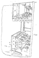
- Figures 1 and 2 show an embodiment of the invention for metal clad or metal enclosed switchgear 10 which includes a metal cabinet or enclosure 12 which may have tandemly and vertically disposed therein drawout three-phase vacuum circuit interrupter apparatus 14 and 16.
- the front panel 15 may have controls thereupon for manually operating the circuit interrupter apparatus.
- the lower circuit interrupter apparatus 14 as shown in Figures 1 and 2 is movably disposed by way of wheels 17 on rails 18 for moving the circuit breaker apparatus 14 into and out of a disposition of electrical contact with live terminals (not shown) disposed in the rear of the cabinet 12.
- the upper circuit interrupter apparatus 16 is movably disposed by way of wheels 19 on rails 20 for moving the upper circuit interrupter apparatus into and out of a disposition of electrical contact with terminals (not shown) in the rear of metal cabinet 12.
- Movable shutters such as shown at 21 may be interposed between the terminals 34 and 36, for example, of either of the three-phase drawout circuit interrupters 14 and 16 for shielding the cabinet high-voltage terminals from inadvertent contact therewith when the three-phase circuit interrupters 14 and 16 have been withdrawn to the position shown in Figure 1.
- Barriers 21 are mechanically moved from in front of the aforementioned terminals when the three-phase circuit interrupters 14 and 16 are moved into a disposition of electrical contact with the aforementioned high-voltage terminals.
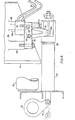
- the three-phase circuit interrupter apparatus 14 may include a front portion 24 in which controls and portions of an operating mechanism are disposed and a rear portion 26.
- the front portion 24 is generally a low-voltage portion and the rear portion 26 is generally a high-voltage portion.
- the high-voltage portion 26 is supported by and electrically insulated from the low-voltage portion 24 by way of upper and lower insulators 28 and 30, respectively.
- vacuum circuit interrupter bottles 32 Disposed within the high-voltage or rear portion 26 are vacuum circuit interrupter bottles 32 which provide circuit interrupting capability between the three-phase terminals 34 and 36, for example.
- the motion and information for opening and closing the contacts of the vacuum circuit interrupter bottles 32 may be supplied by way of linkage 38 from the front portion 24 to the rear portion 26.
- FIGs 3 and 4 a simplified side elevation and front elevation, respectively, of the drawout circuit interrupter apparatus 14 of Figures 1 and 2 are shown.
- the linkage 38 is disposed between the low-voltage portion 24 and the high-voltage portion 26 for the purpose of carrying force which may originate in the low-voltage portion 24 to the high-voltage portion 26 for opening or closing the contacts of the vacuum circuit interrupter 32.
- a more detailed description of the construction and operation of the mechanism 38 is described hereinafter with respect to Figure 6.
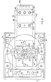
- a circuit interrupter vacuum bottle 32 as well as the stiffened flexible conductor assembly 78 and an attachment device 76 are shown in detail.
- an electrically insulated support member housing 42 having rearwardly (i.e. to the right in the figures) extending abutments 44 and 46 with vertically oriented threaded internal holes therein for accepting complementary bolt members.
- the lateral arrangement of abutments and bolt members is utilized to support the circuit interrupter bottle apparatus 32 and associated contact members 3 4 and 36, for example.
- a rearwardly extending aluminum support member 48 is fastened by way of bolt member 68 to the bottom of the aforementioned abutment 46 at the left as shown in Figures 5 and 24, for example.
- An abutment member 72 which protrudes from the side wall of the aforementioned insulating housing 42 cooperates with a vertically oriented bolt member 74 to secure another portion of the aluminum support member 48 to a sidewall of the housing 42.
- the housing 42 is conveniently supported by the horizontally extending insulators 28 and 30 as is best shown in Figure 3, for example.
- a circular opening 50b is disposed in the support member 48. Opening 50b has a radius generally equal to the radius of a bottom portion of the circuit interrupter vacuum bottle apparatus 32. The latter two portions interact to seat the circuit interrupter apparatus 32 in the horizontal support plate 48.
- a rectangular member 52 having a central circular hole 56 disposed therein is securely fastened to the underside of the support member 48 by way of bolts 51 which protrude upwardly into threaded complementary openings in the support member 48.
- Adjustable bolt members 57 protrude upwardly through plate 52 to adjustably bear against the aforementioned circular end portion 50 of the circuit interrupter 32 to maintain the conducting end plate 32a thereof vertically spaced from the top of the aluminum support plate 48.
- the vertical spacing is represented at 50a, for example, in Figure 20. This prevents significant electrical current from flowing through.
- the bottom contact stem 56a of the movable contact of the vacuum circuit interrupter 32 protrudes downwardly through the opening 56 in the aforementioned rectangular plate 52.
- Layered conductor packets or assemblies 78 are interconnected with the aforementioned stem 56a by way of the aforementioned interconnection assembly 76.
- the stiffened flexible conductor assemblies 78 are partially supported below the support member 48 by way of securing nut and bolt assemblies 80 and 82.
- the nut and bolt assembly 82 also interconnects the conductor assemblies 78 with the electrical terminal 36.
- the characteristic V-shaped pleat or undulation in the conductor assembly 78 horizontally compresses the assemblies between the assembly 76 and the terminal 36 without reducing flexibility for accommodating the travel of the stem 56a in the vertical direction.
- An electrically conducting support member 60 is bolted to and supported by horizontal protrusions 44 and 46 of the aforementioned electrically insulating housing member 42.
- Bolts 62 and 64 are provided for vertically securing member 60 to the protrusions 44 and 66 from the top, respectively.
- the upwardly extending stem of the generally non-moving contact of the circuit interrupter bottle 32 is securely attached to the electrically conducting member 60 by way of securing bolt 58a. Disposed at the rightward end of the electrically conducting member 60 as viewed in Fig. 5 is the aforementioned high voltage terminal 34.
- a unitary stiff, yet flexible, electrically conducting member 100 is shown.
- the member 100 is stiff in that it has the characteristics of being able to support itself in the horizontal without completely drooping to the near vertical disposition as braided copper wire would do in a similar circumstance. However, it is flexible enough to accommodate a certain amount of vertical movement at one end when it is disposed in the horizontal disposition.
- a pleat 108 is disposed therein for purposes described previously.
- At one end of the relatively flat rectangularly shaped thin member 100 is disposed an opening 104a having a radius slightly smaller than the radius of the stem 56a of the circuit interrupter bottle 32.
- Radial slits or cutouts 102 are disposed around the periphery of the opening 104a thus forming tabs 104 which are then slightly offset from the flat planar surface of the member 100 as is best shown in Figure 8.
- Holes or openings 83 and 85 are disposed in the other end of the relatively flat member 100 for interconnection with the fastening apparatus 80 and 82, respectively, as was described previously with respect to Figure 20. The use of the aforementioned tabs 104 will be described hereinafter.
- a nonmagnetic steel rectangularly shaped compression member 110 is depicted.
- Member 110 has a central opening 112 which is of sufficient diameter to allow the stem 56a to easily pass therethrough.
- Outwardly disposed therefrom are openings 114 into which are pressed internally threaded members 116 for accepting complementary threaded portions of bolt members 150 shown in Figure 20.
- the copper tabbed compression member 118 has a circular central opening 123 which is generally of the same diameter as the central opening 104a of the member 100 shown in Figure 7, for example.
- Slits or cutouts 120 are radially placed around the central opening 123 in a manner similar to that described with respect to the member 100 of Figure 7. Consequently, offset tabs 122, best seen in Fig. 11, similar to tabs 104 of Figures 7 and 8 are formed.
- outwardly disposed holes or openings 124 are placed in the member 118 for alignment with similar holes or openings 106 in the member 100.
- a plurality of alternating members 100 and 118 are disposed around an axial portion of the shaft of the stem 56a of the circuit interrupter bottle 32 thus forming a flexible electrically conducting portion 78 such as shown in Figure 20.
- the alternating arrangement of the members 100 and 118 form a plurality of separated flexible electrical conductors within each electrically conducting portion, packet or assembly 78.
- Each of the members 100 makes "three-point" electrical contact with the stem 56a. Consequently, if:-there are ten of the members 100, for example, in a typical section 78, thirty points of electrical contact will be made with the stem 56a.
- Member 126 has a central opening 128 which has a radius sufficiently large to allow the stem 56a to conveniently pass therethrough without deformation. Furthermore, four openings 130 may be provided which align with the openings 124 of the member 118 and the openings 106 of the conducting member 100, for example. The purpose of the utilization of the member 126 will be described more fully hereinafter.
- compression member 132 which is similar to compression member 126 is depicted.
- Compression member 132 differs from compression member 126 in that the central opening 136 of the compression member 132 is significantly smaller in radius than the central opening 128 of the member 126. This is due to the fact that the lower end portion of the shaft 56a has a reduced-radius threaded portion thereof which conveniently fits through the opening 136 so that the member 132 may conveniently fit over the threaded portion without fitting over the main shaft of the stem 56a. This in essence abuts the member 132 against the bottom of a significant portion of the stem 56a.
- a metal bell crank-to-stem force transfer member 138 is depicted.
- Member 138 has vertically rising lips 148 on ⁇ two opposing sides thereof ahd relatively larger vertically rising members 140 on the other two 'opposing sides thereof. Holes or openings 146 which align with the previously described holes or openings 130, 134, 124. and 106 are provided. Furthermore, a central opening 148 which fits around the reduced threaded portion of the shaft 56a much in the way that the hole 136 of member 132 does is also shown.
- a circular hole 142 is disposed for interconnection with pivot pins 97 of the bell crank assembly in a manner to be described hereinafter with respect to Figure 6.
- two spacers 126 are slipped onto the shafts
- another assembly 78 which includes alternating members 100 and 118 are formed along the shaft in a manner previously discussed.
- electrically conducting member 132 with its reduced central opening 136 is disposed over the threaded portion of the shaft 56a and abuts against the shoulder between the reduced threaded portion and the enlarged shaft of the member 56a.
- the member 138 is disposed in a manner shown with respect to Figure 20 and a bolt (not shown in Figure 20) is disposed over the reduced threaded portion of the member 56a thus compressing the main body of the member.138 against the member 132 and thus against the lower shoulder of the shaft 56a thus securing the latter two members to the shaft 56a.
- bolt members 150 are fed through holes 146 of member 138, holes 134 of member 132, holes 106 of member 100, holes 124 of member 118, holes 130 of member 126 and finally into the threads of the lipped members 116 of the uppermost compression member 110.
- FIG. 6 the linkage arrangement 38 for interconnecting the circuit interrupter of the high-voltage section 26 with a force providing apparatus such as a motor or crank in low-voltage section 24 is shown.
- a crankshaft member 86 may be pivotally attached to an insulating rod 84 the other end of which is interconnected with one pivot pin 88a of a bell crank 88.
- a third pivot 97 of the bell crank member 88 is interconnected with the member 138 in the journals 142 thereof so that the shaft 56a may move upwardly and downwardly as viewed in Figure 6 as the crank mechanism 86 rotatates causing the insulating shaft 84 to move in a substantially horizontal direction is shown in Figure 6.
- the electrically interconnecting attachment device 76 and its associated stiff flexible contact portions 78 move upwardly and downwardly in a corresponding fashion.
- the member 76 would deter or prevent the stem 56 from operating under the influence of the bell crank 88.
- the unique arrangement of the interconnection in the interconnecting device 76 provides for low resistance contact between the stem 56 and the flexible conductors 78.
- FIG. 22 and 23 another embodiment of the invention is shown which is useful for relatively higher ranges of operating current.
- FIG. 22 and 23 Similar elements are identified with primed (') reference Figures.
- the circuit interrupter bottle of the embodiment of Figures 22 and 23 is identified by the reference symbol 32' indicating that it is different from the circuit interrupter 32 of other embodiments and other Figures.
- elements 100', 110' and 118', 126' 132' and 138' are similar but relatively larger than elements 100, 110, 118, 126, 132 and 138 of Figures 20 and 21.
- the central circular opening in the present case is larger than the corresponding central circular openings 104a, 112, 123, 128, 136 and 148, respectively.
- the bolt holes in the present embodiment are slightly larger in diameter and further offset from the center of each element than the corresponding bolt holes 106, 114, 124, 130, 134 and 146 of the embodiments of Figures 20 and 21.
- Spacers 152' associated with bolt 80' also differ from the spacer arrangement shown with regard to Figure 20, for example. It is also to be noted that the terminal 36' is of a larger size and different construction than the terminal 36 of Figure 20, for example. Otherwise, the operation of the apparatus shown in Figure 22 is similar to the operation of the apparatus shown in Figure 20 in that a bell crank member (not shown) interconnected at 97 with the interconnecting member 138' is utilized to cause the stem 56a' to move upwardly and downwardly to close and open, respectively, the contacts of the vacuum circuit interrupter apparatus bottle 32' while the flexible conductors of the packets or portions 78' move or flex accordingly.
- a bell crank member (not shown) interconnected at 97 with the interconnecting member 138' is utilized to cause the stem 56a' to move upwardly and downwardly to close and open, respectively, the contacts of the vacuum circuit interrupter apparatus bottle 32' while the flexible conductors of the packets or portions 78' move or flex accordingly.
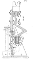
- FIG. 24 and 25 still another embodiment of the invention is shown in which a vacuum circuit interrupter 32 is disposed electrically between two high-voltage terminals 172 and 174.
- the aforementioned high-voltage terminals and vacuum interrupter are insulatingly spaced apart at appropriate places by the insulators 160, 162, 164 and 168.
- Electrical interconnecting apparatus shown at 178 is utilized in cooperation with an insulating movement providing means 176 to cause packets 78 " of stiff flexible conductors 100" to remove current from the circuit interrupter bottle 32.
- a top view of a stiff flexible conductor 100" is shown.
- holes 182 are disposed at the ends of the conductor 100' and a central hole 184 is disposed in the center to accommodate the interconnection between the force providing apparatus 176 and the stem interconnection apparatus 178 of Figure 25.
- offset holes 180 are disposed in the main body of the conductor to assist in dissipating heat.
- the entire conductor 100" is disposed between the insulators 160 and 168 to provide a larger heat radiating surface than would normally be found if the conductor were merely disposed between the connecting portion 178 and the insulator 168.
- the apparatus taught with respect to the embodiments of this invention has many advantages.
- One advantage lies in the fact that current may be transferred from an elongated terminal stem or conductor to a relatively flat conductor by utilizing the teachings of the present invention.
- electrical current may be transferred from a circular member through a high conductivity, low resistant joint to a relatively flat member.
- Another advantage lies in the fact that by using multiple flat conductors in conjunction with a single circular stem in a laminate and tab construction a given volume of copper in a circular to flat interface of multiple three-point contacts may be utilized for transferring current between the latter two members through an interface of significantly reduced contact resistance.
- the apparatus taught with respect to the embodiments of this invention has many advantages.
- One advantage lies in the fact that current may be transferred from a movable terminal stem or conductor to a relatively fixed conductor by utlizing the teachings of the present invention.
- Another advantage lies in the fact that a contact resistance in the current carrying capabilities of a given amount of electrical conductor may be retained while the conductor is rendered more flexible by utilizing the concepts of the teachings of this invention.
- Another advantage lies in the fact that higher ratings may be enjoyed for a given amount of electrical conductor and for given space limits by utilizing the concepts of the teachings of this invention.
Landscapes
- Engineering & Computer Science (AREA)
- Power Engineering (AREA)
- Push-Button Switches (AREA)
- High-Tension Arc-Extinguishing Switches Without Spraying Means (AREA)
- Breakers (AREA)
- Portable Nailing Machines And Staplers (AREA)
- Air Bags (AREA)
- Fittings On The Vehicle Exterior For Carrying Loads, And Devices For Holding Or Mounting Articles (AREA)
Applications Claiming Priority (4)
| Application Number | Priority Date | Filing Date | Title |
|---|---|---|---|
| US233723 | 1981-02-12 | ||
| US06/233,721 US4384179A (en) | 1981-02-12 | 1981-02-12 | Stiff flexible connector for a circuit breaker or other electrical apparatus |
| US233721 | 1981-02-12 | ||
| US06/233,723 US4376235A (en) | 1981-02-12 | 1981-02-12 | Electrical junction of high conductivity for a circuit breaker or other electrical apparatus |
Publications (3)
| Publication Number | Publication Date |
|---|---|
| EP0058519A2 true EP0058519A2 (de) | 1982-08-25 |
| EP0058519A3 EP0058519A3 (en) | 1983-07-20 |
| EP0058519B1 EP0058519B1 (de) | 1986-12-30 |
Family
ID=26927170
Family Applications (1)
| Application Number | Title | Priority Date | Filing Date |
|---|---|---|---|
| EP82300674A Expired EP0058519B1 (de) | 1981-02-12 | 1982-02-11 | Elektrische Verbindung hoher Leitfähigkeit für einen Schalter oder andere elektrische Apparate |
Country Status (10)
| Country | Link |
|---|---|
| EP (1) | EP0058519B1 (de) |
| AR (1) | AR229114A1 (de) |
| AU (1) | AU558250B2 (de) |
| BR (1) | BR8200610A (de) |
| DE (1) | DE3274920D1 (de) |
| ES (1) | ES8307412A1 (de) |
| HU (1) | HU183819B (de) |
| IN (1) | IN155577B (de) |
| MX (1) | MX151574A (de) |
| NO (1) | NO158520C (de) |
Cited By (11)
| Publication number | Priority date | Publication date | Assignee | Title |
|---|---|---|---|---|
| EP0380980A1 (de) * | 1989-01-30 | 1990-08-08 | Sprecher Energie AG | Vakuumschalter |
| CH678126A5 (en) * | 1989-01-30 | 1991-07-31 | Sprecher Energie Ag | Medium=voltage vacuum switch with rolling contact arrangement - has switch surrounded by section of external connector which extends into insulating housing with aperture for contact plunger |
| EP0634765A1 (de) * | 1993-07-16 | 1995-01-18 | Eaton Corporation | Flexible Verbindung für einen Leistungsschalter |
| EP0731479A2 (de) * | 1995-03-07 | 1996-09-11 | Eaton Corporation | Verbesserte flexible Verbindung für einen Leistungsschalter |
| EP1139367A1 (de) * | 2000-03-31 | 2001-10-04 | Schneider Electric Industries SA | Unterbrechungseinheit mit Vakuumrohr und Befestigungsmitteln sowie eine solche Einheit benutzende Schaltanlage |
| EP1139358A1 (de) * | 2000-03-31 | 2001-10-04 | Schneider Electric Industries SA | Elektrisches Schaltgerät mit einer Vakuumröhre und eine flexible elektrische Verbindung |
| EP1331655A3 (de) * | 2002-01-29 | 2005-02-09 | Siemens Aktiengesellschaft | Einstellbares Kontaktstück für einen Vakuumschalter |
| WO2006040243A1 (de) | 2004-10-14 | 2006-04-20 | Siemens Aktiengesellschaft | Kupplungsvorrichtung mit kühlkörper |
| CN103681089A (zh) * | 2012-07-26 | 2014-03-26 | Ls产电株式会社 | 断路器 |
| CN108511258A (zh) * | 2017-02-27 | 2018-09-07 | 西门子公司 | 用于真空断路器的极柱及其真空断路器 |
| DE102017206866A1 (de) * | 2017-04-24 | 2018-10-25 | Siemens Aktiengesellschaft | Anschlusselement für einen Bewegkontakt einer Vakuumschaltröhre und gasisolierte Schaltanlage mit einem Anschlusselement für einen Bewegkontakt einer Vakuumschaltröhre |
Citations (5)
| Publication number | Priority date | Publication date | Assignee | Title |
|---|---|---|---|---|
| DE1233043B (de) * | 1965-04-02 | 1967-01-26 | Busch Jaeger Duerener Metall | Befestigung einer Kontaktplatte an einer Buechse |
| US3603753A (en) * | 1968-02-28 | 1971-09-07 | Westinghouse Electric Corp | Metalclad switchgear using vacuum interrupter elements |
| US3739120A (en) * | 1971-07-15 | 1973-06-12 | Mc Graw Edison Co | Flexible switch support and terminal connector |
| US3941959A (en) * | 1973-04-30 | 1976-03-02 | Siemens Aktiengesellschaft | Vacuum switching apparatus with a drive unit at ground potential |
| US4146766A (en) * | 1975-05-23 | 1979-03-27 | Associated Electrical Industries Limited | Actuating mechanisms for vacuum interrupters |
-
1982
- 1982-01-07 IN IN32/CAL/82A patent/IN155577B/en unknown
- 1982-01-07 AU AU79273/82A patent/AU558250B2/en not_active Expired
- 1982-01-12 NO NO820066A patent/NO158520C/no unknown
- 1982-01-21 MX MX191061A patent/MX151574A/es unknown
- 1982-01-28 AR AR288267A patent/AR229114A1/es active
- 1982-02-04 BR BR8200610A patent/BR8200610A/pt not_active IP Right Cessation
- 1982-02-11 EP EP82300674A patent/EP0058519B1/de not_active Expired
- 1982-02-11 DE DE8282300674T patent/DE3274920D1/de not_active Expired
- 1982-02-11 HU HU82418A patent/HU183819B/hu not_active IP Right Cessation
- 1982-02-11 ES ES509510A patent/ES8307412A1/es not_active Expired
Patent Citations (5)
| Publication number | Priority date | Publication date | Assignee | Title |
|---|---|---|---|---|
| DE1233043B (de) * | 1965-04-02 | 1967-01-26 | Busch Jaeger Duerener Metall | Befestigung einer Kontaktplatte an einer Buechse |
| US3603753A (en) * | 1968-02-28 | 1971-09-07 | Westinghouse Electric Corp | Metalclad switchgear using vacuum interrupter elements |
| US3739120A (en) * | 1971-07-15 | 1973-06-12 | Mc Graw Edison Co | Flexible switch support and terminal connector |
| US3941959A (en) * | 1973-04-30 | 1976-03-02 | Siemens Aktiengesellschaft | Vacuum switching apparatus with a drive unit at ground potential |
| US4146766A (en) * | 1975-05-23 | 1979-03-27 | Associated Electrical Industries Limited | Actuating mechanisms for vacuum interrupters |
Cited By (19)
| Publication number | Priority date | Publication date | Assignee | Title |
|---|---|---|---|---|
| EP0380980A1 (de) * | 1989-01-30 | 1990-08-08 | Sprecher Energie AG | Vakuumschalter |
| CH678126A5 (en) * | 1989-01-30 | 1991-07-31 | Sprecher Energie Ag | Medium=voltage vacuum switch with rolling contact arrangement - has switch surrounded by section of external connector which extends into insulating housing with aperture for contact plunger |
| EP0634765A1 (de) * | 1993-07-16 | 1995-01-18 | Eaton Corporation | Flexible Verbindung für einen Leistungsschalter |
| EP0731479A2 (de) * | 1995-03-07 | 1996-09-11 | Eaton Corporation | Verbesserte flexible Verbindung für einen Leistungsschalter |
| EP0731479A3 (de) * | 1995-03-07 | 1998-04-01 | Eaton Corporation | Verbesserte flexible Verbindung für einen Leistungsschalter |
| EP1139367A1 (de) * | 2000-03-31 | 2001-10-04 | Schneider Electric Industries SA | Unterbrechungseinheit mit Vakuumrohr und Befestigungsmitteln sowie eine solche Einheit benutzende Schaltanlage |
| EP1139358A1 (de) * | 2000-03-31 | 2001-10-04 | Schneider Electric Industries SA | Elektrisches Schaltgerät mit einer Vakuumröhre und eine flexible elektrische Verbindung |
| FR2807203A1 (fr) * | 2000-03-31 | 2001-10-05 | Schneider Electric Ind Sa | Module de coupure comportant une ampoule a vide et des moyens de fixation, et appareillage electrique de coupure comportant un tel module |
| FR2808117A1 (fr) * | 2000-03-31 | 2001-10-26 | Schneider Electric Ind Sa | Appareillage electrique de coupure comportant une ampoule a vide et une liaison electrique flexible |
| US6410875B2 (en) | 2000-03-31 | 2002-06-25 | Schneider Electric Industries Sa | Electrical switchgear apparatus comprising a vacuum cartridge and a flexible electrical connector |
| US6410874B2 (en) | 2000-03-31 | 2002-06-25 | Schneider Electric Industries Sa | Breaking module comprising a vacuum cartridge and fixing means, and an electrical switchgear apparatus comprising such a module |
| EP1331655A3 (de) * | 2002-01-29 | 2005-02-09 | Siemens Aktiengesellschaft | Einstellbares Kontaktstück für einen Vakuumschalter |
| WO2006040243A1 (de) | 2004-10-14 | 2006-04-20 | Siemens Aktiengesellschaft | Kupplungsvorrichtung mit kühlkörper |
| CN101036208B (zh) * | 2004-10-14 | 2010-06-16 | 西门子公司 | 具有冷却体的耦合装置 |
| CN103681089A (zh) * | 2012-07-26 | 2014-03-26 | Ls产电株式会社 | 断路器 |
| US9070521B2 (en) | 2012-07-26 | 2015-06-30 | Lsis Co., Ltd. | Circuit breaker |
| CN103681089B (zh) * | 2012-07-26 | 2015-12-23 | Ls产电株式会社 | 断路器 |
| CN108511258A (zh) * | 2017-02-27 | 2018-09-07 | 西门子公司 | 用于真空断路器的极柱及其真空断路器 |
| DE102017206866A1 (de) * | 2017-04-24 | 2018-10-25 | Siemens Aktiengesellschaft | Anschlusselement für einen Bewegkontakt einer Vakuumschaltröhre und gasisolierte Schaltanlage mit einem Anschlusselement für einen Bewegkontakt einer Vakuumschaltröhre |
Also Published As
| Publication number | Publication date |
|---|---|
| DE3274920D1 (en) | 1987-02-05 |
| MX151574A (es) | 1984-12-19 |
| NO158520C (no) | 1988-09-21 |
| NO158520B (no) | 1988-06-13 |
| AU558250B2 (en) | 1987-01-22 |
| AU7927382A (en) | 1982-08-19 |
| ES509510A0 (es) | 1983-06-16 |
| ES8307412A1 (es) | 1983-06-16 |
| EP0058519A3 (en) | 1983-07-20 |
| AR229114A1 (es) | 1983-06-15 |
| BR8200610A (pt) | 1982-12-14 |
| HU183819B (en) | 1984-06-28 |
| IN155577B (de) | 1985-02-16 |
| NO820066L (no) | 1982-08-13 |
| EP0058519B1 (de) | 1986-12-30 |
Similar Documents
| Publication | Publication Date | Title |
|---|---|---|
| US4384179A (en) | Stiff flexible connector for a circuit breaker or other electrical apparatus | |
| CN1038373C (zh) | 金属外壳内充高压气体的多相高压开关装置 | |
| EP2485348A2 (de) | Schaltanlage | |
| US4758172A (en) | Power distribution busway system | |
| CA2473272C (en) | Gas segregator barrier for electrical switching apparatus | |
| EP0058519B1 (de) | Elektrische Verbindung hoher Leitfähigkeit für einen Schalter oder andere elektrische Apparate | |
| US4376235A (en) | Electrical junction of high conductivity for a circuit breaker or other electrical apparatus | |
| US6921862B2 (en) | Connector for conductor bars | |
| US5486662A (en) | Flexible connector for a circuit interrupter | |
| CA2171167C (en) | Flexible connector for a circuit breaker | |
| US6142807A (en) | High current and low current electrical busway systems having compatible bus plug | |
| KR102417925B1 (ko) | 가스 절연되는 스위치기어용 회로차단기 | |
| CA2160805A1 (en) | Switching device | |
| KR102333579B1 (ko) | 가스 절연된 스위치기어용 디스커넥터 폴 | |
| US6473294B1 (en) | System for distributing energy and data in energy distributing facilities | |
| CN1528038A (zh) | 金属封闭式配电盘 | |
| US3352988A (en) | Means for mounting and electrically interconnecting circuit interrupting devices | |
| EP0058402B1 (de) | Gasisolierte Schaltanlage | |
| US20080105654A1 (en) | Polyphase Switching Device Comprising at Least Three Similar Interrupter Units | |
| US3958093A (en) | Metalclad switchgear using vacuum interrupter elements with improved resilient supporting means | |
| EP1227558B1 (de) | Schaltanlage | |
| EP3186812A1 (de) | Kombinierte elektrische hochspannungsvorrichtung | |
| EP4235721A1 (de) | Schaltvorrichtung zur stromverteilung | |
| CN111886763B (zh) | 用于气体绝缘开关设备的紧凑式断路器 | |
| EP1705767A1 (de) | Kombinierter Trenn-Erdungsschalter |
Legal Events
| Date | Code | Title | Description |
|---|---|---|---|
| PUAI | Public reference made under article 153(3) epc to a published international application that has entered the european phase |
Free format text: ORIGINAL CODE: 0009012 |
|
| AK | Designated contracting states |
Designated state(s): BE CH DE FR GB IT NL SE |
|
| PUAL | Search report despatched |
Free format text: ORIGINAL CODE: 0009013 |
|
| AK | Designated contracting states |
Designated state(s): BE CH DE FR GB IT LI NL SE |
|
| 17P | Request for examination filed |
Effective date: 19840113 |
|
| GRAA | (expected) grant |
Free format text: ORIGINAL CODE: 0009210 |
|
| ITF | It: translation for a ep patent filed | ||
| AK | Designated contracting states |
Kind code of ref document: B1 Designated state(s): BE CH DE FR GB IT LI NL SE |
|
| REF | Corresponds to: |
Ref document number: 3274920 Country of ref document: DE Date of ref document: 19870205 |
|
| ET | Fr: translation filed | ||
| PLBE | No opposition filed within time limit |
Free format text: ORIGINAL CODE: 0009261 |
|
| STAA | Information on the status of an ep patent application or granted ep patent |
Free format text: STATUS: NO OPPOSITION FILED WITHIN TIME LIMIT |
|
| 26N | No opposition filed | ||
| ITTA | It: last paid annual fee | ||
| PGFP | Annual fee paid to national office [announced via postgrant information from national office to epo] |
Ref country code: SE Payment date: 19950124 Year of fee payment: 14 |
|
| EAL | Se: european patent in force in sweden |
Ref document number: 82300674.7 |
|
| PGFP | Annual fee paid to national office [announced via postgrant information from national office to epo] |
Ref country code: DE Payment date: 19950224 Year of fee payment: 14 |
|
| PGFP | Annual fee paid to national office [announced via postgrant information from national office to epo] |
Ref country code: NL Payment date: 19950228 Year of fee payment: 14 |
|
| PGFP | Annual fee paid to national office [announced via postgrant information from national office to epo] |
Ref country code: BE Payment date: 19950308 Year of fee payment: 14 |
|
| PGFP | Annual fee paid to national office [announced via postgrant information from national office to epo] |
Ref country code: CH Payment date: 19950420 Year of fee payment: 14 |
|
| PG25 | Lapsed in a contracting state [announced via postgrant information from national office to epo] |
Ref country code: SE Effective date: 19960212 |
|
| PG25 | Lapsed in a contracting state [announced via postgrant information from national office to epo] |
Ref country code: LI Free format text: LAPSE BECAUSE OF NON-PAYMENT OF DUE FEES Effective date: 19960228 Ref country code: CH Free format text: LAPSE BECAUSE OF NON-PAYMENT OF DUE FEES Effective date: 19960228 Ref country code: BE Effective date: 19960228 |
|
| BERE | Be: lapsed |
Owner name: WESTINGHOUSE ELECTRIC CORP. Effective date: 19960228 |
|
| PG25 | Lapsed in a contracting state [announced via postgrant information from national office to epo] |
Ref country code: NL Effective date: 19960901 |
|
| REG | Reference to a national code |
Ref country code: CH Ref legal event code: PL |
|
| NLV4 | Nl: lapsed or anulled due to non-payment of the annual fee |
Effective date: 19960901 |
|
| PG25 | Lapsed in a contracting state [announced via postgrant information from national office to epo] |
Ref country code: DE Effective date: 19961101 |
|
| PGFP | Annual fee paid to national office [announced via postgrant information from national office to epo] |
Ref country code: GB Payment date: 20010104 Year of fee payment: 20 |
|
| PGFP | Annual fee paid to national office [announced via postgrant information from national office to epo] |
Ref country code: FR Payment date: 20010201 Year of fee payment: 20 |
|
| REG | Reference to a national code |
Ref country code: GB Ref legal event code: IF02 |
|
| PG25 | Lapsed in a contracting state [announced via postgrant information from national office to epo] |
Ref country code: GB Free format text: LAPSE BECAUSE OF EXPIRATION OF PROTECTION Effective date: 20020210 |
|
| REG | Reference to a national code |
Ref country code: GB Ref legal event code: PE20 Effective date: 20020210 |