EP0057579A2 - Elektrische Steckverbinder - Google Patents
Elektrische Steckverbinder Download PDFInfo
- Publication number
- EP0057579A2 EP0057579A2 EP82300451A EP82300451A EP0057579A2 EP 0057579 A2 EP0057579 A2 EP 0057579A2 EP 82300451 A EP82300451 A EP 82300451A EP 82300451 A EP82300451 A EP 82300451A EP 0057579 A2 EP0057579 A2 EP 0057579A2
- Authority
- EP
- European Patent Office
- Prior art keywords
- conductor
- housing
- clamping means
- parts
- contact
- Prior art date
- Legal status (The legal status is an assumption and is not a legal conclusion. Google has not performed a legal analysis and makes no representation as to the accuracy of the status listed.)
- Ceased
Links
Images
Classifications
-
- H—ELECTRICITY
- H01—ELECTRIC ELEMENTS
- H01R—ELECTRICALLY-CONDUCTIVE CONNECTIONS; STRUCTURAL ASSOCIATIONS OF A PLURALITY OF MUTUALLY-INSULATED ELECTRICAL CONNECTING ELEMENTS; COUPLING DEVICES; CURRENT COLLECTORS
- H01R4/00—Electrically-conductive connections between two or more conductive members in direct contact, i.e. touching one another; Means for effecting or maintaining such contact; Electrically-conductive connections having two or more spaced connecting locations for conductors and using contact members penetrating insulation
- H01R4/24—Connections using contact members penetrating or cutting insulation or cable strands
- H01R4/2416—Connections using contact members penetrating or cutting insulation or cable strands the contact members having insulation-cutting edges, e.g. of tuning fork type
- H01R4/242—Connections using contact members penetrating or cutting insulation or cable strands the contact members having insulation-cutting edges, e.g. of tuning fork type the contact members being plates having a single slot
- H01R4/2425—Flat plates, e.g. multi-layered flat plates
- H01R4/2429—Flat plates, e.g. multi-layered flat plates mounted in an insulating base
- H01R4/2433—Flat plates, e.g. multi-layered flat plates mounted in an insulating base one part of the base being movable to push the cable into the slot
-
- H—ELECTRICITY
- H01—ELECTRIC ELEMENTS
- H01R—ELECTRICALLY-CONDUCTIVE CONNECTIONS; STRUCTURAL ASSOCIATIONS OF A PLURALITY OF MUTUALLY-INSULATED ELECTRICAL CONNECTING ELEMENTS; COUPLING DEVICES; CURRENT COLLECTORS
- H01R4/00—Electrically-conductive connections between two or more conductive members in direct contact, i.e. touching one another; Means for effecting or maintaining such contact; Electrically-conductive connections having two or more spaced connecting locations for conductors and using contact members penetrating insulation
- H01R4/24—Connections using contact members penetrating or cutting insulation or cable strands
- H01R4/2416—Connections using contact members penetrating or cutting insulation or cable strands the contact members having insulation-cutting edges, e.g. of tuning fork type
- H01R4/242—Connections using contact members penetrating or cutting insulation or cable strands the contact members having insulation-cutting edges, e.g. of tuning fork type the contact members being plates having a single slot
-
- H—ELECTRICITY
- H01—ELECTRIC ELEMENTS
- H01R—ELECTRICALLY-CONDUCTIVE CONNECTIONS; STRUCTURAL ASSOCIATIONS OF A PLURALITY OF MUTUALLY-INSULATED ELECTRICAL CONNECTING ELEMENTS; COUPLING DEVICES; CURRENT COLLECTORS
- H01R13/00—Details of coupling devices of the kinds covered by groups H01R12/70 or H01R24/00 - H01R33/00
- H01R13/58—Means for relieving strain on wire connection, e.g. cord grip, for avoiding loosening of connections between wires and terminals within a coupling device terminating a cable
-
- H—ELECTRICITY
- H01—ELECTRIC ELEMENTS
- H01R—ELECTRICALLY-CONDUCTIVE CONNECTIONS; STRUCTURAL ASSOCIATIONS OF A PLURALITY OF MUTUALLY-INSULATED ELECTRICAL CONNECTING ELEMENTS; COUPLING DEVICES; CURRENT COLLECTORS
- H01R13/00—Details of coupling devices of the kinds covered by groups H01R12/70 or H01R24/00 - H01R33/00
- H01R13/66—Structural association with built-in electrical component
- H01R13/6608—Structural association with built-in electrical component with built-in single component
- H01R13/6633—Structural association with built-in electrical component with built-in single component with inductive component, e.g. transformer
Definitions
- This invention relates to electric connectors.
- Electric connectors having a two-part housing with at least one insulation piercing contact mounted in one part of the housing for connection to a respective insulated conductor, and conductor clamping means formed by or carried on the two parts of the housing spaced lengthwise from the insulation piercing contact or contacts are known (for example, as shown in UK Patent Specification No. 1462920).
- the conductor clamping means is of such a form that, when the two parts of the housing are moved together to force the conductor onto its respective insulation piercing contact to make an electrical connection to the contact, said clamping means clamp the insulated conductor in such a way that substantially no tensile force is applied to that part of the conductor extending between the clamping means and the insulation piercing contact.
- the clamping means can also serve as a stress relief device for the electric connector.
- the conductor clamping means preferably comprises a first shoulder on one part of the housing which co-operates with a second shoulder on the other part of the housing in such a way that, as the two parts of the housing are moved together, the insulated conductor is distorted at two longitudinally spaced positions along its length so that the insulated conductor is gripped between the two shoulders as the conductor is forced onto its respective contact.
- the connector has two similar co-operating shoulders, one on each part of the housing, positioned on the side of the clamping means remote from the contact or contacts, which shoulders similarly grip the conductor and serve with said first and second shoulders as a strain relief device.
- the or each insulation piercing contact preferably has two cutting edges between which the insulated conductor is forced, the cutting edges piercing the insulation on the conductor to mkae the electrical connection between the conductor and its contact.
- the or each insulation piercing contact can comprise a spike which pierces the conductor insulation to make the electrical connection.
- the arrangement of the electric connector is such that there is one insulation piercing contact for each insulated conductor.
- the two parts of the housing are preferably hinged together.
- the two parts can be separately formed but capable of being interlocked together.
- the invention has the advantage that because no tensile force is applied to that part of the conductor extending between the clamping means and the insulation piercing contact when the two parts of the connector housing are moved together, risk of tearing the conductor and bending of the insulation piercing contact is substantially reduced.
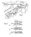
- the electric connector 1 of part of an electrical detonator circuit shown in Figure 1 comprises a two-part housing 2, two insulation piercing contacts 3 (only one is visible) and clamping means.
- An electric cable 4 comprising two insulated conductors 5 is shown ready to be fitted to the connector 1.
- the clamping means comprises an upstanding shoulder 6 of groove 7 in one part 8 of the housing 2 and a co-operating downwardly projecting shoulder 9 of rib 10 on the other part 11 of the housing 2.
- the two parts 8, 11 of the housing 2 are hinged together.
- the arrangement is such that when the two parts 8, 11 of the housing 2 are moved together, the cable 4 is clamped at point A ( Figure 2) between the co-operating shoulders 6, 9 as the conductors 5 are forced onto the insulation piercing contacts 3. Clamping of the cable 4 at point A is so effected that further movement together of the two parts 8, 11 of the housing 2 apply substantially no tensile force to those parts of the conductor 5 extending between point A and the insulation piercing contacts 3, and that a tensile force is applied to that part of the cable 4 on the side of point A remote from the contacts 3 to cause that part of the cable to move in the direction X towards point A.
- Rib 10 has a second shoulder 12 ' which moves into groove 7 to cooperate with a second shoulder 13 on the groove which grips the cable 4 to form the stress relief device. Both the clamping means and the stress relief device distort the cable through an angle of substantially 90° at two spaced positions.
Landscapes
- Multi-Conductor Connections (AREA)
- Coupling Device And Connection With Printed Circuit (AREA)
- Connections By Means Of Piercing Elements, Nuts, Or Screws (AREA)
Applications Claiming Priority (2)
| Application Number | Priority Date | Filing Date | Title |
|---|---|---|---|
| GB8102850 | 1981-01-30 | ||
| GB8102850 | 1981-01-30 |
Publications (2)
| Publication Number | Publication Date |
|---|---|
| EP0057579A2 true EP0057579A2 (de) | 1982-08-11 |
| EP0057579A3 EP0057579A3 (de) | 1983-06-15 |
Family
ID=10519339
Family Applications (1)
| Application Number | Title | Priority Date | Filing Date |
|---|---|---|---|
| EP82300451A Ceased EP0057579A3 (de) | 1981-01-30 | 1982-01-28 | Elektrische Steckverbinder |
Country Status (2)
| Country | Link |
|---|---|
| EP (1) | EP0057579A3 (de) |
| GB (1) | GB2092399B (de) |
Cited By (8)
| Publication number | Priority date | Publication date | Assignee | Title |
|---|---|---|---|---|
| GB2168860A (en) * | 1984-12-20 | 1986-06-25 | Starpoint Electrics Ltd | Lampholder |
| FR2638575A1 (fr) * | 1988-11-03 | 1990-05-04 | Neiman Sa | Procede et dispositif de connexion electrique d'un ensemble contenu dans un boitier |
| DE4324841A1 (de) * | 1993-07-23 | 1995-01-26 | Grote & Hartmann | Verfahren und Vorrichtung zur Stromversorgung optionaler, elektrisch angetriebener Sonderausstattungseinrichtungen, z. B. in einem Kraftfahrzeug, einem elektrisch betriebenen Haushaltsgerät oder dergleichen |
| EP0671780A1 (de) * | 1994-03-10 | 1995-09-13 | Reichle + De-Massari AG Elektro-Ingenieure | Mehrfach-Kontaktstifthalter für Schwachstrom-Anlagen |
| FR2768862A1 (fr) * | 1997-09-22 | 1999-03-26 | Infra Sa | Prise de courant faible a capuchon arriere organisateur |
| WO2000069025A1 (en) * | 1999-05-06 | 2000-11-16 | Cabit S.R.L. | Terminal board for the connection of wires, in particular of electric energy conductors |
| FR2882815A1 (fr) * | 2005-03-04 | 2006-09-08 | Delta Caps Initiators Soc Par | Dispositif de connexion pour detonateurs |
| US9868867B1 (en) | 2012-11-26 | 2018-01-16 | Russell Scott Manley | Solvents and uses thereof |
Family Cites Families (2)
| Publication number | Priority date | Publication date | Assignee | Title |
|---|---|---|---|---|
| US4099819A (en) * | 1976-09-13 | 1978-07-11 | Bunker Ramo Corporation | Modular termination system for telecommunication devices |
| US4195898A (en) * | 1977-12-27 | 1980-04-01 | Bunker Ramo Corporation | Patchcord connector |
-
1982
- 1982-01-28 EP EP82300451A patent/EP0057579A3/de not_active Ceased
- 1982-01-28 GB GB8202410A patent/GB2092399B/en not_active Expired
Cited By (14)
| Publication number | Priority date | Publication date | Assignee | Title |
|---|---|---|---|---|
| GB2168860A (en) * | 1984-12-20 | 1986-06-25 | Starpoint Electrics Ltd | Lampholder |
| FR2638575A1 (fr) * | 1988-11-03 | 1990-05-04 | Neiman Sa | Procede et dispositif de connexion electrique d'un ensemble contenu dans un boitier |
| DE4324841A1 (de) * | 1993-07-23 | 1995-01-26 | Grote & Hartmann | Verfahren und Vorrichtung zur Stromversorgung optionaler, elektrisch angetriebener Sonderausstattungseinrichtungen, z. B. in einem Kraftfahrzeug, einem elektrisch betriebenen Haushaltsgerät oder dergleichen |
| CN1045846C (zh) * | 1994-03-10 | 1999-10-20 | 赖希勒及迪-马沙里有限公司 | 用于弱电设备的多触脚接线器 |
| EP0671780A1 (de) * | 1994-03-10 | 1995-09-13 | Reichle + De-Massari AG Elektro-Ingenieure | Mehrfach-Kontaktstifthalter für Schwachstrom-Anlagen |
| AU681227B2 (en) * | 1994-03-10 | 1997-08-21 | Reichle & De-Massari Ag | Multiple contact pin holder for weak current installations |
| US5662493A (en) * | 1994-03-10 | 1997-09-02 | Reichle + De-Massari Ag | Multiple contact pin holder for weak current installations |
| FR2768862A1 (fr) * | 1997-09-22 | 1999-03-26 | Infra Sa | Prise de courant faible a capuchon arriere organisateur |
| WO1999016153A1 (fr) * | 1997-09-22 | 1999-04-01 | Infra + | Prise de courant faible a capuchon arriere organisateur |
| US6267617B1 (en) | 1997-09-22 | 2001-07-31 | Infra | Low voltage plug adapter with organizing rear bonnet |
| WO2000069025A1 (en) * | 1999-05-06 | 2000-11-16 | Cabit S.R.L. | Terminal board for the connection of wires, in particular of electric energy conductors |
| FR2882815A1 (fr) * | 2005-03-04 | 2006-09-08 | Delta Caps Initiators Soc Par | Dispositif de connexion pour detonateurs |
| WO2006092437A1 (fr) * | 2005-03-04 | 2006-09-08 | Chemical Holdings International Ltd | Dispositif de connexion pour detonateurs |
| US9868867B1 (en) | 2012-11-26 | 2018-01-16 | Russell Scott Manley | Solvents and uses thereof |
Also Published As
| Publication number | Publication date |
|---|---|
| GB2092399A (en) | 1982-08-11 |
| GB2092399B (en) | 1985-02-06 |
| EP0057579A3 (de) | 1983-06-15 |
Similar Documents
| Publication | Publication Date | Title |
|---|---|---|
| US4560224A (en) | Flat cable termination | |
| EP0034000B1 (de) | Anschlussklemme für Schaltplatten | |
| CA1086390A (en) | Electrial connector for a flat cable having parallel spaced, insulated conductors | |
| US3778749A (en) | Connector | |
| GB1320022A (en) | Electrical connectors | |
| EP0007706A1 (de) | Elektrischer Verbinder zur Anwendung bei der Herstellung von Abzweigverbindungen an Leitern | |
| CA2219668A1 (en) | Connecting clamp for electrical conductors | |
| US4564256A (en) | Flat cable transition connector | |
| ATE127622T1 (de) | Torsionsschneidklemmverbinder. | |
| US4455057A (en) | Insulation piercing terminal | |
| CA1083238A (en) | Electrical contact terminal with laterally offset connection slots | |
| EP0057579A2 (de) | Elektrische Steckverbinder | |
| CA1140227A (en) | Method of terminating shielded electrical cable and an assembly comprising an electrical connector terminating such cable | |
| KR950015852A (ko) | 케이블 터미네이션용 전기 커넥터 | |
| GB1490197A (en) | Solderless termination system | |
| EP0306343A3 (de) | Elektrischer Steckverbinder | |
| US4522460A (en) | Connecting means for closely spaced conductors | |
| US4019800A (en) | Uniplanar electrical contact | |
| US4725247A (en) | Cable splicing assembly | |
| EP0154179A3 (en) | Connection of conductors especially for high current terminals | |
| EP0084257B1 (de) | Anschlussanordnung und Anschlusselement für Flachkabel | |
| GB2130815A (en) | Electrical connectors | |
| US4679878A (en) | Insulation-piercing electrical contact and connector incorporating the same | |
| US20050090139A1 (en) | Contact | |
| GB2112216A (en) | Electrical connectors for use telecommunications equipment |
Legal Events
| Date | Code | Title | Description |
|---|---|---|---|
| PUAI | Public reference made under article 153(3) epc to a published international application that has entered the european phase |
Free format text: ORIGINAL CODE: 0009012 |
|
| AK | Designated contracting states |
Designated state(s): AT BE CH DE FR IT LI LU NL SE |
|
| 17P | Request for examination filed |
Effective date: 19820802 |
|
| PUAL | Search report despatched |
Free format text: ORIGINAL CODE: 0009013 |
|
| AK | Designated contracting states |
Designated state(s): AT BE CH DE FR IT LI LU NL SE |
|
| RAP1 | Party data changed (applicant data changed or rights of an application transferred) |
Owner name: BICC PUBLIC LIMITED COMPANY Owner name: BURNDY CORPORATION |
|
| STAA | Information on the status of an ep patent application or granted ep patent |
Free format text: STATUS: THE APPLICATION HAS BEEN REFUSED |
|
| 18R | Application refused |
Effective date: 19851103 |
|
| RIN1 | Information on inventor provided before grant (corrected) |
Inventor name: CUNLIFFE, ROBERT LEONARD |