EP0057464B1 - Capteur utilisant des fibres optiques - Google Patents
Capteur utilisant des fibres optiques Download PDFInfo
- Publication number
- EP0057464B1 EP0057464B1 EP82100736A EP82100736A EP0057464B1 EP 0057464 B1 EP0057464 B1 EP 0057464B1 EP 82100736 A EP82100736 A EP 82100736A EP 82100736 A EP82100736 A EP 82100736A EP 0057464 B1 EP0057464 B1 EP 0057464B1
- Authority
- EP
- European Patent Office
- Prior art keywords
- light
- sensor
- spectral
- optical fibre
- fibre conductor
- Prior art date
- Legal status (The legal status is an assumption and is not a legal conclusion. Google has not performed a legal analysis and makes no representation as to the accuracy of the status listed.)
- Expired
Links
- 239000000835 fiber Substances 0.000 claims description 87
- 230000003595 spectral effect Effects 0.000 claims description 47
- 239000004020 conductor Substances 0.000 claims description 23
- 239000013307 optical fiber Substances 0.000 claims description 23
- 230000005540 biological transmission Effects 0.000 claims description 22
- 230000003287 optical effect Effects 0.000 claims description 21
- 238000010521 absorption reaction Methods 0.000 claims description 18
- 239000003086 colorant Substances 0.000 claims description 16
- 230000035945 sensitivity Effects 0.000 claims description 16
- 239000004973 liquid crystal related substance Substances 0.000 claims description 5
- 238000005259 measurement Methods 0.000 description 10
- 238000011156 evaluation Methods 0.000 description 6
- 230000008054 signal transmission Effects 0.000 description 6
- 230000000694 effects Effects 0.000 description 5
- 238000010586 diagram Methods 0.000 description 4
- 238000012545 processing Methods 0.000 description 4
- 238000001228 spectrum Methods 0.000 description 4
- 238000004891 communication Methods 0.000 description 3
- 238000010276 construction Methods 0.000 description 3
- 238000013461 design Methods 0.000 description 3
- 230000007423 decrease Effects 0.000 description 2
- 230000007613 environmental effect Effects 0.000 description 2
- 238000000034 method Methods 0.000 description 2
- 238000000926 separation method Methods 0.000 description 2
- 239000000126 substance Substances 0.000 description 2
- 239000002253 acid Substances 0.000 description 1
- 230000001154 acute effect Effects 0.000 description 1
- 239000006117 anti-reflective coating Substances 0.000 description 1
- 230000000712 assembly Effects 0.000 description 1
- 238000000429 assembly Methods 0.000 description 1
- BJQHLKABXJIVAM-UHFFFAOYSA-N bis(2-ethylhexyl) phthalate Chemical compound CCCCC(CC)COC(=O)C1=CC=CC=C1C(=O)OCC(CC)CCCC BJQHLKABXJIVAM-UHFFFAOYSA-N 0.000 description 1
- 238000009530 blood pressure measurement Methods 0.000 description 1
- 239000011248 coating agent Substances 0.000 description 1
- 238000000576 coating method Methods 0.000 description 1
- 239000012141 concentrate Substances 0.000 description 1
- 239000013078 crystal Substances 0.000 description 1
- 239000006185 dispersion Substances 0.000 description 1
- 238000006073 displacement reaction Methods 0.000 description 1
- 230000008030 elimination Effects 0.000 description 1
- 238000003379 elimination reaction Methods 0.000 description 1
- 238000005516 engineering process Methods 0.000 description 1
- 229910052732 germanium Inorganic materials 0.000 description 1
- GNPVGFCGXDBREM-UHFFFAOYSA-N germanium atom Chemical compound [Ge] GNPVGFCGXDBREM-UHFFFAOYSA-N 0.000 description 1
- 239000003365 glass fiber Substances 0.000 description 1
- 230000012447 hatching Effects 0.000 description 1
- 238000002955 isolation Methods 0.000 description 1
- 239000000463 material Substances 0.000 description 1
- 230000005693 optoelectronics Effects 0.000 description 1
- 229920003023 plastic Polymers 0.000 description 1
- 238000004886 process control Methods 0.000 description 1
- 239000010453 quartz Substances 0.000 description 1
- VYPSYNLAJGMNEJ-UHFFFAOYSA-N silicon dioxide Inorganic materials O=[Si]=O VYPSYNLAJGMNEJ-UHFFFAOYSA-N 0.000 description 1
- 125000006850 spacer group Chemical group 0.000 description 1
- 238000012546 transfer Methods 0.000 description 1
- 238000007740 vapor deposition Methods 0.000 description 1
Images


Classifications
-
- G—PHYSICS
- G01—MEASURING; TESTING
- G01D—MEASURING NOT SPECIALLY ADAPTED FOR A SPECIFIC VARIABLE; ARRANGEMENTS FOR MEASURING TWO OR MORE VARIABLES NOT COVERED IN A SINGLE OTHER SUBCLASS; TARIFF METERING APPARATUS; MEASURING OR TESTING NOT OTHERWISE PROVIDED FOR
- G01D5/00—Mechanical means for transferring the output of a sensing member; Means for converting the output of a sensing member to another variable where the form or nature of the sensing member does not constrain the means for converting; Transducers not specially adapted for a specific variable
- G01D5/26—Mechanical means for transferring the output of a sensing member; Means for converting the output of a sensing member to another variable where the form or nature of the sensing member does not constrain the means for converting; Transducers not specially adapted for a specific variable characterised by optical transfer means, i.e. using infrared, visible, or ultraviolet light
- G01D5/28—Mechanical means for transferring the output of a sensing member; Means for converting the output of a sensing member to another variable where the form or nature of the sensing member does not constrain the means for converting; Transducers not specially adapted for a specific variable characterised by optical transfer means, i.e. using infrared, visible, or ultraviolet light with deflection of beams of light, e.g. for direct optical indication
- G01D5/30—Mechanical means for transferring the output of a sensing member; Means for converting the output of a sensing member to another variable where the form or nature of the sensing member does not constrain the means for converting; Transducers not specially adapted for a specific variable characterised by optical transfer means, i.e. using infrared, visible, or ultraviolet light with deflection of beams of light, e.g. for direct optical indication the beams of light being detected by photocells
Definitions
- the present invention relates to a fiber optic sensor device for measuring a physical parameter.
- Fiber optic signal transmission has become an important technological innovation in electronic systems in recent years. Among the reasons for the advantages of fiber optic signal transmission over previous electrical signal transmission is the availability of additional bandwidth combined with the elimination of electromagnetic interference. Other reasons are the convenient separation of the electrical potentials of different system components.
- Fiber optic transmission has been used to communicate over medium and long distances and for digital data transmission in certain industrial applications where electromagnetic interference or electrical isolation is particularly important. Fiber optic transmission lines have also been used in connection with high voltage switches with power plant control and with process control, electric ovens. The application in aircraft and in motor vehicles is discussed.
- signal communication in digital form is carried out not only between data processing units, but also in communication with input and output devices.
- a special signal sensitivity exists between sensors and data processing devices. That is why fiber-optic communication on a digital basis was used for signal transmission between sensors and the control system (see Control Engineering, Feb. 1979, pp. 30 to 33).
- the sensor arrangements serve to achieve input information relative to the physical parameters that are important for the control system, such as. for example temperature, pressure, position, flow, speed etc.
- sensor arrangements can be constructed so that they do not require an energy source on the measurement side.
- Such sensor arrangements work entirely on optical principles and strictly with fiber-optic signal transmission.
- These sensor arrangements can be referred to as passive sensors. They have the advantage of high protection against electromagnetic interference and the simplicity of the system.
- Sensor assemblies can also be constructed to have an auxiliary power source for scanning to eventually arrive at optical signals that can be carried through the fiber optic transmission line.
- the energy source can be an optical, an electrical or any other source, while the scanning principle and the signal transmission are still optical in nature. Such arrangements can be referred to as active arrangements. Providing an auxiliary source on the measurement side usually entails additional costs.
- a sensor device is known from DE-A-29 20 489.
- the modulator device consists of a filter that influences one spectral color more than the other. Both spectral colors influenced by the filter reach the detector window of a detector device.
- a sensor device is known in which the light generating device emits two spectral colors which are transmitted via an optical fiber line. Only one spectral color reaches the modulator device, which influences the light supplied as a function of a physical parameter. The other spectral color is returned unaffected to a fiber line.
- the modulator device attenuates one spectral color as a function of the physical parameter to be measured.
- DE-A-30 07 462 discloses a spectrally selective modulator device in the form of a liquid crystal layer arranged in the beam path of the light supplied from an optical fiber line. It is not clear from the entire publication whether the light generating device there emits several spectral colors or only one, as would be the case, for example, with a laser. In addition, nothing is said in this document about the detector device.
- the object of the invention is to enrich the technology in the field of fiber-optic sensor devices with a novel sensor device that opens up a multitude of design options.
- the invention has the following advantages: With the device according to the invention, the measurement signal is not or only slightly exposed to disturbing environmental influences.
- the sensor device according to the invention can withstand hostile environmental conditions, such as moisture, oil, acid and electromagnetic interference or interference. It has a very simple structure. It can be manufactured relatively easily and cheaply. It requires a single one to maintain a measurement signal from the measurement side distant from the evaluation side Light source. It can be used with self-propelled or self-moving systems or processes.
- a device that splits and / or selects the light such as a prism or an interference filter, is arranged at the light exit end of the first light-transmitting fiber. This device splits the light received by the first light-transmitting fiber into its spectral components.
- the sensor device also has a second light-transmitting fiber. The light entry end of the second fiber receives individual spectral components, whereby or where the selection of these components depends on the physical parameter to be measured.
- the second fiber emits the spectral component (s) through its light exit end.
- a light detector is assigned to this light exit end and receives the spectral component (s) emitted by the second light-transmitting fiber.
- the output signal of the detector is a measure of the physical parameter.
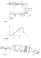
- a first light-transmitting fiber or input fiber line 1 is illuminated with light from a light source 2.
- the input fiber line 1 is made of a light-conducting material and, according to FIG. 1, can be flexible at its end sections.
- the input fiber line 1 can consist of a single optical fiber. However, it preferably consists of a fiber optic cable which contains various glass fibers. The axis of symmetry is denoted by a.
- the light source 2 emits a relatively broad spectrum of light. For example, it can produce white light w, which contains all visible spectral components.
- the light source 2 can be an incandescent lamp or a plurality of LEDs (light-emitting diodes) that emit in different colors or spectra.
- the light source 2 can emit infrared, visible or ultraviolet light.
- the light from the light source 2 is guided to the other end of the optical cable 1 and from there through a collimator containing two diaphragms 3a and 3b to a light-dispersing element which is represented by a prism 10.
- the diaphragms 3a and 3b and collimators are parallel to and at a distance between the optical cable 1 and the prism 10 arranged from each other so that an at least well approximated parallel light beam is obtained.
- the openings or holes in both plates 3a and 3b are equal to or smaller than the diameter of the light-transmitting core of the input line 1.
- the prism 10 causes the incoming light beam to split into two spectral colors. In the example shown, only the high frequency component or blue component b reaches the input end of a second light-transmitting fiber or output fiber line 4. The long-wave or red component r is lost.
- the prism 10 can be rotated about an axis 11. The twisting is effected under the influence of the parameter or quantity M that is to be measured. Alternatively, prism 10 could be held in a fixed position, whereas the input end of output fiber line 4 has been rotated relative to prism 10. Using a prism 10 is less expensive than using other color selective or light dispersing elements such as a Fabry-Perrot etalon.
- the output fiber line 4 is of the same structure as the input fiber line 1. Light leaving the output fiber line 4 reaches a light detector 5 which is sensitive to the received light. This light detector 5 is arranged directly at the end of the output fiber line 4.
- the light detector 5 is preferably a photoelectronic device which contains, for example, a photodiode. In the example shown, it is a photo element.
- the output voltage of the light detector 5 is measured by means of a measuring instrument 6 or otherwise processed.
- the input fiber line 1 and / or the output fiber line 4 can be fixed by means of fastening elements 7.
- the prism 10 Under the influence of the parameter M to be measured, the prism 10 is rotated about its axis 11. When the prism 10 rotates, different spectral components hit the input end of the return fiber cable 4, causing different colors to be received by the photodetector 5. The intensity of the incident light is measured. When the prism 10 moves under the influence of the parameter M clockwise in the direction of the double arrow, the frequency of the light received by the output fiber line 4 decreases continuously until finally only the red light component r of the white light w is received and by the detector 5 is measured.
- Any physical parameter, such as pressure, temperature, location, change, etc., that enables a force to be exerted in the direction of the double arrow can be used as a quantity M to be measured.
- the detector 5 is differently sensitive to the different spectral colors in order to distinguish them either by a sensitivity of the detector varying over the spectral range of the light source 2 or by a special filter (not shown) arranged in front of the actual receiver, which filter-receiver combination has such properties.
- FIG. 2 shows the known relationship between the relative spectral sensitivity A and the wavelength ⁇ of a photo or optoelectronic germanium element, which can advantageously be used as the photo detector device 5.
- the detector 5 is frequency selective. It is evident from the diagram in FIG. 2 that in the spectral range between the wavelength Ab of the blue light component b and the wavelength A r of the red light component r, the sensitivity A varies almost directly proportional to the wavelength ⁇ or inversely proportional to the light frequency. The same applies to the measured value indicated by the measuring instrument 6. It is important that a defined relationship exists between this value and the position of the prism 10, which is rotated under the influence of the parameter M to be measured.
- FIG. 3 shows an embodiment of a fiber optic sensor which is similar to that shown in FIG. 1.
- This embodiment can be applied to precision measurements.
- a first lens 3c is arranged between the output end or end of the input fiber line 1 and the prism 10. The output end is located at the focal point of the lens 3c.
- the first lens 3c generates a parallel light beam or a parallel beam.
- a second lens 3d is arranged between the prism 10 and the input end or end of the output fiber line 4. This second lens 3d concentrates the scattered light beam in the input end of the line 4, which is arranged in the focal point of this lens 3d. Both lenses 3c and 3d can be of low dispersion.
- the arrangement of the lenses 3c, 3d and the prism 10 is the same as in the known prism spectrometer. I.e. the prism 10, the second lens 3d and the opening or mouth of the output fiber line 4 can be rotated about the axis 11 of the prism 10. Rotation of the construction composed of the prism 10, the lens 3d and the opening of the line 4 results in a change in color in accordance with the physical parameter M. This color change is determined by the detector device 5.
- This directional filter 3e can be arranged between the prism 10 and the input end of the fiber line 4.
- the directional filter 3e eliminates rays that are not incident at a specific angle.
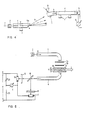
- FIG. 4 shows an embodiment of a fiber-optic sensor arrangement, which represents a variant of the embodiment according to FIG. 1.
- the main difference between the exec 1 and the embodiment according to FIG. 4 lies in the fact that in the embodiment according to FIG. 4 the spectral separation of the white light emitted by the light source 2 is effected by the input fiber line 1 itself.
- the output end or output-side end of the input fiber line 1 is provided with an end surface which includes an acute angle a with the axis of symmetry a. The angle can be approximately 45 °.
- the white light w is broken down into its spectral colors.
- the output end of the line 1 acts like a prism 10a.
- the dispersed light containing the blue and red components b and r is guided to the input end of the output fiber line 4. In the position shown, only the high-frequency component b reaches the input surface of the output fiber line 4.
- the input fiber line 1 and the rear part of the output fiber line 4 are spatially fixed by holding elements 7, while the front part of the output fiber line 4 can be moved by an element 9 under the influence of the parameter M.
- the element 9 consists of a ring surrounding the end and a rod. The movement can be carried out on a circle surrounding the end face of the input fiber line 1. As a result, the light detector receives 5 light of changing colors.
- FIG. 4 shows an embodiment which uses a section oblique to the axis of symmetry a at the exit end of the incoming fiber line 1 to maintain the prism effect.
- This embodiment further uses a transversely movable output fiber 4 for selective light frequency recording, whereby or wherein the movement of the end part or section of the fiber 4 is related to the parameter M to be measured (pressure, temperature, position, etc.).
- the interference filter 12-14 can be designed in the manner of a known Fabry-Perrot interferometer.
- the interference filter 12-14 essentially consists of two flat quartz plates 12 and 13 (Fabry-Perrot plates) which are arranged at a certain distance d from one another and parallel to one another. On their outer surfaces they are provided with anti-reflective coatings produced by vapor deposition, and their mutually facing inner surfaces are mirrored. Air or a transparent plastic material 14 can be located between the plates 12 and 13. If the distance d is changed under the influence of the quantity M to be measured, for example by a piezoelectric or magnetostrictive spacer 14 arranged between the two plates 12 and 13, a field strength measurement can be carried out.
- transmission maxima with very small half-value widths take place at certain wavelengths. These wavelengths are essentially determined by the distance d between the two plates 12 and 13 and by the refractive index of the medium between the plates 12 and 13. As a result, only light that has certain wavelengths is transmitted, and the intensity of the red and blue light components is a measure of the transmitted wavelength and therefore of the distance d between the plates 12 and 13.
- the light emanating from the output fiber line 4 is fed via a beam splitter 15 to a first and a second light-sensitive device, each of which consists of a photoresistor or photoconductive cell or a designated 16 or 17 preceding absorption filter 18 or 19 there.
- the photoconductive cells 16, 17 together with two additional resistors 20, 21 form a bridge circuit.
- This bridge circuit is supplied by a stabilized DC voltage U.
- a measuring instrument 6 is arranged in the diagonal of the bridge circuit. This measuring instrument 6 is designed as a zero display, so that in addition to the size, the direction of the quantity M can also be determined.
- the resistor 20 is variable and allows zeroing in a very simple way.
- curve W denotes the spectral distribution of the light emitted by light source 2.
- the amplitude of the emitted light wave components which have a wavelength that is smaller than a wavelength A, is negligibly small.
- Lightwave components of a wavelength between the wavelengths ⁇ 11 and A "have an essentially constant maximum amplitude. From the wavelength A", the intensity of the corresponding light components decreases rapidly with increasing wavelength.
- the mutual distance d of the two plane-parallel plates 12 and 13 of the interference filter 12-14 changes from a minimum value d1 to a maximum value d2. Accordingly, the interference filter 12-14 transmits light in these positions d1 and d2 from the corresponding marked spectral ranges, which are identified by hatching in FIG.
- curve 22 indicates the relative spectral sensitivity A as a function of the wavelength ⁇ for the first receiving device, which consists of the absorption filter 18 and the photoconductive cell 16.
- the curve 23 gives the relatively spectral sensitivity A as a function of the wavelength A for the second reception device, which consists of the absorption filter 19 and the photoconductive cell 17.
- the receiving device can be chosen so that a symmetrical relative position of the sensitivity characteristics 22 and 23 is present.
- the resistance of each of the two photosensitive cells 16 and 17 varies by a maximum value which corresponds to the change in sensitivity AA. If the photosensitive cells 16 and 17 are arranged in a bridge circuit, this change in resistance is carried out twice and results in a greater deflection of the measuring instrument 6.
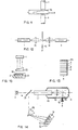
- FIG. 8 shows an embodiment which has a particularly simple construction of an interference filter.
- the mutually facing reflecting surfaces here consist of the output-side end surface of the input fiber line 1 and the input-side end surface of the output fiber line 4. These end surfaces are arranged plane-parallel to one another. They can be partially coated with a layer of a light-reflecting substance.
- An elastic medium can be arranged in the gap. This medium can be optically denser than lines 1 and 4. It can consist of any of the well known substances used in Fabry-Perrot interferometers, for example oil.
- the two fiber lines 1 and 4 extend to the inside of a completely closed housing 25 which is filled with a gaseous medium 24.
- the input fiber line 1 is fixedly connected to the housing 25, whereas the output fiber line 4 can be moved along its axis of symmetry a under the influence of a quantity M1 to be measured.
- This mobility is achieved by a fastening or end plate 26 and an elastic bellows 26a.
- the bellows 26a is attached to the plate 26 at one end and to the housing 25 at the other end.
- an additional quantity or an additional parameter M2 influences the wavelength of the light that has passed through the filter.
- a cylindrical tube piece 27 is provided on the housing 25, in the opening of which it can slide in bolts or pistons, in particular without play. Movement of this piston 28 under the influence of the quantity M2 results in a change in the pressure of the gaseous medium 24 in the interior of the housing 25. Since the refractive index of the gaseous medium varies with its density, pressure changes inside the housing 25 result in corresponding changes in the refractive index. Accordingly, the wavelength of the transmitted light depends on both quantities M1 and M2.
- the quantities are preferably represented by pressures.
- An advantage of the embodiment according to FIG. 8 is that it works more easily on an optical basis. It allows the measurement of an absolute pressure M1 if the quantity M2 is kept constant.
- FIG. 9 shows a measuring device which can be used to measure the difference M1 ⁇ M2 between two pressures M1, M2.
- the housing 25a is a tube.
- the pressure M1 prevails in the upper end of the tube 25a.
- a disc or plate 25b which is pierced by a plurality of holes, is fixed in the tube 25a.
- the first fiber optic transmission line 1 extends in the lower part of the tube 25a. It is attached by an upper pressure-tight wall element 25v.
- the outlet end of the pipe 1 is fixed in a hole located in the central part of the disk 25d. This end represents the fixed end of the measuring arrangement.
- the movable end of the measuring arrangement is represented by the light entry end of the second fiber optic transmission line 4.
- This end surface is arranged opposite the first-mentioned end surface by means of a movable part or a movable plate 26.
- the plate 26 is tightly or sealingly attached to the upper end of a bellows 26, the lower end of which is attached to the inner wall of the tube 25a by means of an annular body 26y.
- the flexible end of the second fiber optic transmission line 4 is inserted into the interior of the tube 25a, namely through a lower pressure-tight wall element 25d in the lower part of the tube 25a. It should be noted that the inlet end of the second line 4 can be moved vertically with respect to the outlet end of the first line 1.
- the distance d of the gap between these ends depends on the pressure difference M1 ⁇ M2.
- the transmitted wavelength depends on the difference d.
- a cover element or a Cover plate 25x may be provided.
- This chamber contains a reference pressure M2.
- the reference M2 can either be 0 (evacuated chamber) or have a predetermined value other than 0.
- the measuring arrangement measures the differential pressure Ml-M2, ie the pressure that exceeds the reference pressure M2.
- Figure 10 shows an embodiment in which the input fiber line 1 and the output fiber line 4 are combined to form a single fiber line 1,4. Accordingly, only one transmission line is required.
- the light w emitted by the light source 2 radiates through a partially transparent mirror 29 in the transmission line 1, 4 and then a scanning element, for example a liquid crystal 30.
- the crystal 30 is exposed to the influence of a magnetic field, which represents the quantity M to be measured.
- the effect of the magnetic field is such that the color of the light radiating through the liquid crystal 30 changes, for example, from white to blue b.
- the light radiating through the liquid crystal 30 strikes a mirror 31 and is reflected back from there into the fiber line 1, 4.
- the returning light b reflected by the semitransparent mirror 29 strikes a beam splitter 15.
- FIG. 10 shows a somewhat simpler light detector arrangement.
- the two photoconductive cells form a voltage divider which is acted upon by a voltage stabilized by a tens diode 32.
- the measuring instrument 6 measures the voltage of the photoconductive cell 17.
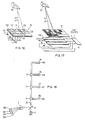
- FIG. 11 An interference filter 12, 14 movable with a gap between two optical transmission lines 1 and 4 in the direction of the light beam is shown in FIG. However, it is also possible to design the interference filter so that the movement takes place in a direction vertical to the light beam. The distance d should vary in such an interference filter.
- a vertically movable interference filter is shown in FIG. 11.
- a transparent medium 14a is arranged between lines 1 and 2.
- This medium 14a contains a number of stages. In other words, the thickness of the medium increases from level to level. Depending on the parameter M and accordingly on the position of the medium 14a, each of these stages determines the optically effective or optical distance d.
- the embodiment shown which has a vertical displacement possibility, can be chosen where there are space problems.
- FIGS. 12 and 14 Sensor arrangements with absorption filters 14b in the gap between the transmission lines 1 and 4 are shown in FIGS. 12 and 14. In both cases, the absorption filter 14b is movable perpendicular to the main direction of the light beam entering the gap. In FIG. 12, the absorption filter 14a is arranged between two lenses 40 and 42, which are provided for focusing the incident light beam or for collecting the transmitted light beam.
- the absorption filter 14b can consist of a certain number of sections e, f, g, h, each of which is transparent to light of a certain wavelength. Therefore, different sections e, f, g, h represent different colors in the optical spectrum of a white light-emitting light source. As indicated, several different color levels can be provided. In contrast, the colors of the absorption filter 14b (not shown) can also overlap from section to section.
- an absorption filter 14b is used in an arrangement which is similar to the arrangement shown in FIG.
- the filter 14b is contained in a cylindrical housing 44.
- the exit or exit end of the combined fiber optic line 1, 4 is accommodated in the housing 44.
- Light from the exit end is directed through a lens 46 as a convergent beam onto the filter 14b.
- the filter 14b can be displaced under the influence of a parameter M perpendicular to the main direction of the light indicated by arrows.
- a spring 48 counteracts the upward movement of the filter 14b.
- the light of a certain color transmitted by the filter 14b is reflected by an inner end face of the housing 44. This end surface is curved and acts as a reflector 31.
- the light is reflected back through the absorption filter 14b and the lens 46 into the transmission line 1, 4.
- the light is directed towards a prism 10p by means of a semitransparent spatula 29.
- the prism 10p is part of a frequency sensitive detector. It deflects the incoming light in the direction of a field 50 of photosensitive elements. Each of these elements can be electrically connected to a measuring instrument 52 or some other type of evaluation device. In the embodiment according to FIG. 14, all parts and components, including the prism 10p and the individual sensitive elements of the field 50, are fixed. This is a special advantage.
- absorption filters have been used as discriminators 18 and 19 in combination with photoconductive cells 16 and 17.
- the absorption filter 14b is used in combination with a prism 10p.
- the monochrome light that the prism 10p reaches from the movable filter 14b can be a very fine light beam.
- This light beam or light bundle is shifted on the field 50 in accordance with the shift of the filter 14b.
- the electrical resistance of an optical sensor 50 can be changed in accordance with the position of the light beam and as indicated in FIG. 17.
- field 50 is used as a digital gray-scale discriminator, which is explained in connection with FIG. 16.
- FIG. Another form of light-sensing device or device is shown in FIG. Instead of a filter 18 or 19, this device has a stepped interference filter 56 in a fixed position. This interference filter 56 can be smaller than the filter 14a in FIG. 11.
- a field 50 of individual detectors can also or also be used as a photosensitive device or device.
- Each of the individual detectors is assigned to a stage of the filter 56 here. Measuring instruments or data processing devices provide an evaluation of the measured values.
- the Gray scale discriminator consists of several lines of light-sensitive diodes D10, D20, D24, ..., D36 or other optical sensors (such as photo resistors) and free spaces between them.
- Diode D10 and a free space are arranged in the first line.
- the diode D20, a free space, the diode D24 and another free space are arranged.
- the diode D30, a free space, the diode D32, another free space, the diode D34, another free space, the diode D36 and a further free space are arranged.
- the diodes D10-D36 are connected by resistors R10, R20,...
- R36 to one or more voltage sources which have or have the voltage U.
- the signals tapped at resistors R10 ... R36 are evaluated. Accordingly, the first row provides a total of two digits or numbers, the next row a total of four numbers, etc.
- various combinations of exposed diodes are found D10, D36 instead.
- D10, D36 When starting at the right end, none of the diodes D10 to D36 are affected.
- diode D36 first receives light. In the following, the diode D24 is affected. Then the two diodes D24 and D34 are exposed. Finally, on the left side of the field 50, all three diodes D10, D20 and 'D30 light are received from the light fan.
- FIG. 17 shows that, instead of the arrangement of the diodes D10-D36 shown in FIG. 16, it is possible to use simple diode or resistance strips P10, P20, P30, ... and the digitization effect through a coating 62 which has the pattern shown in Figure 16.
- FIG. 17 shows that the varying combinations of resistance values can be passed to an evaluation circuit 64 which contains a shift register. This shift register is basically a storage element. Data is read into this element in parallel and read out in series.
- the arrangement of Figure 17 can be used in conjunction with the arrangement of Figure 14, i.e. that a reflector 31 and a combined fiber line 1, 4 is used for input and output of the scanning light beam.
- a large number of optical sensors or transmitters are often required for electronic control systems. Such systems may require installing as many optical fiber lines from the individual measurement points to a central processing station as there are measurement points. 18 and 20 show that in such a case the number of optical transmission lines can be considerably reduced if the principles of the light frequency modulation and multiplexing methods according to the invention are used.
- the light source of a light source 2 emits light of a wide spectrum.
- the light enters a light conduit 33 through a partially or semi-transparent mirror 15.
- the light then travels via so-called T-couplers 34 to optical transmitters 85e-85h, each of which is arranged at one end of a single fiber line that branches off from the T-couplers 34.
- Each of these transmitters 85e-85h can, for example, have a frequency-selective filter, such as the Fabry-Perrot filter 12 to 14 shown in FIG. 5 or the filter element 30 shown in FIG. 10, which is followed by a reflector or mirror, for example the reflector 31 in of the arrangement according to FIG. 10.
- the curve W in FIG. 19 represents the spectral distribution of the light emitted by the light source 2.
- the light emitted has a relatively wide spectrum. Due to a suitable design or construction of their filters, the individual receiving devices 86e ⁇ 86h are only transparent for spectral ranges designated by E-H in FIG. 19 and correspondingly assigned. Accordingly, the receiving device 86E is only transparent for the spectral range E, the receiving device 86F only for the spectral range F, etc.
- the curves e-h in the upper part of FIG. 19 represent, on a greatly reduced ordinate scale, the spectral sensitivities of the individual transmitters 85e ⁇ 85h, which contain a frequency-selective filter. Their transmission bandwidths correspond approximately to those of the associated receiving devices 86E-86H.
- transmission bands can be shifted under the influence of parameters Me, Mf, Mg, Mh, for example in the manner shown in FIG.
- the transmission range of the frequency-selective filter and the associated receiving device overlap and the degree of overlap depends on the influence of the measured quantity Me, Mf, Mg and Mh. Only light components of appropriate size are received by the receiving devices 86e, 86f, 86g and 86h.
- the color multiplex device according to FIG. 18 can be used to measure various parameters in a motor vehicle.
- FIG. 20 shows a second embodiment of an optical multiplex operation in which a so-called star coupler 87 is used.
- this line 1 branches into fiber lines for light, which lead to individual transmitters 85e, 85f, 85g, etc., each of which has a frequency-selective filter and which responds to an associated parameter Me, Mf, Mg.
- the returning light components are coupled into a common output fiber line 4 for light. These components are directed to the light receiving devices 86E, 86F, 86G, etc., as in the arrangement according to FIG. 18.
- optical networks shown in Figures 18 and 20 can also be combined with any or any other.
- fifth of the optical networks shown in FIG. 18 can be excited by a star coupler 87 according to FIG. 20. This allows twenty optical transmitters to be used.
Landscapes
- Physics & Mathematics (AREA)
- General Physics & Mathematics (AREA)
- Investigating Or Analysing Materials By Optical Means (AREA)
- Optical Transform (AREA)
- Length Measuring Devices By Optical Means (AREA)
Claims (23)
Applications Claiming Priority (2)
| Application Number | Priority Date | Filing Date | Title |
|---|---|---|---|
| US06/230,808 US4408123A (en) | 1981-02-02 | 1981-02-02 | Fiber optical sensor device for measuring a physical parameter |
| US230808 | 1988-08-09 |
Publications (3)
| Publication Number | Publication Date |
|---|---|
| EP0057464A2 EP0057464A2 (fr) | 1982-08-11 |
| EP0057464A3 EP0057464A3 (en) | 1984-07-18 |
| EP0057464B1 true EP0057464B1 (fr) | 1988-05-25 |
Family
ID=22866661
Family Applications (1)
| Application Number | Title | Priority Date | Filing Date |
|---|---|---|---|
| EP82100736A Expired EP0057464B1 (fr) | 1981-02-02 | 1982-02-02 | Capteur utilisant des fibres optiques |
Country Status (3)
| Country | Link |
|---|---|
| US (1) | US4408123A (fr) |
| EP (1) | EP0057464B1 (fr) |
| DE (1) | DE3278541D1 (fr) |
Families Citing this family (25)
| Publication number | Priority date | Publication date | Assignee | Title |
|---|---|---|---|---|
| SE455345B (sv) * | 1982-12-30 | 1988-07-04 | Asea Ab | Ljusalstrande element innefattande ett optiskt filter som ger den emitterade signalen en temperaturoberoende uteffekt, samt anvendning av det ljusalstrande elementet |
| US4536651A (en) * | 1983-03-14 | 1985-08-20 | Pitney Bowes Inc. | Optical weighing scale utilizing a prism |
| US4594504A (en) * | 1983-09-08 | 1986-06-10 | Rosemount Inc. | Light modulation sensor in a vortex shedding flowmeter |
| GB8414671D0 (en) * | 1984-06-08 | 1984-07-11 | Sira Ltd | Wavelength detection |
| JPS61235731A (ja) * | 1985-04-11 | 1986-10-21 | Sharp Corp | 感圧素子 |
| GB8514671D0 (en) * | 1985-06-11 | 1985-07-10 | Asbury A J | Optical transducer interrogation device |
| AU6215186A (en) * | 1985-09-06 | 1987-03-12 | University Of Liverpool, The | Displacement measurement |
| US4958930A (en) * | 1985-12-11 | 1990-09-25 | E. I. Du Pont De Nemours And Company | Apparatus for monitoring thickness variations in a film web |
| GB8610654D0 (en) * | 1986-05-01 | 1986-08-20 | Bicc Plc | Movement detection |
| GB8625471D0 (en) * | 1986-10-24 | 1986-11-26 | Bicc Plc | Displacement detection |
| US4942767A (en) * | 1986-11-19 | 1990-07-24 | Massachusetts Institute Of Technology | Pressure transducer apparatus |
| US4926696A (en) * | 1986-11-19 | 1990-05-22 | Massachusetts Institute Of Technology | Optical micropressure transducer |
| US5052228A (en) * | 1986-11-19 | 1991-10-01 | Massachusetts Institute Of Technology | Shear stress measuring device |
| GB2198841B (en) * | 1986-12-10 | 1990-12-12 | Plessey Co Plc | Improvements relating to optical sensors |
| US4859844A (en) * | 1988-02-24 | 1989-08-22 | Hughes Aircraft Company | Comb filter pressure/temperature sensing system |
| US4849624A (en) * | 1988-06-24 | 1989-07-18 | The Boeing Company | Optical wavelength division multiplexing of digital encoder tracks |
| US4950886A (en) * | 1989-06-30 | 1990-08-21 | Claus Richard O | Partially reflecting optical fiber splice for temperature and strain measurement |
| US5262639A (en) * | 1992-04-15 | 1993-11-16 | Norscan Instruments Ltd. | Fiber optic cable monitoring method and apparatus including moisture detection and bending loss detection |
| US5714680A (en) * | 1993-11-04 | 1998-02-03 | The Texas A&M University System | Method and apparatus for measuring pressure with fiber optics |
| US5727110A (en) * | 1995-09-29 | 1998-03-10 | Rosemount Inc. | Electro-optic interface for field instrument |
| US5771114A (en) * | 1995-09-29 | 1998-06-23 | Rosemount Inc. | Optical interface with safety shutdown |
| AR004288A1 (es) * | 1995-11-13 | 1998-11-04 | Siemens Ag | Estructura de instalación de cable de fibras ópticas. |
| US6604427B1 (en) * | 1999-07-19 | 2003-08-12 | Nate Coleman | Bellow-type pressure sensing apparatus |
| GB2366542B (en) * | 2000-09-09 | 2004-02-18 | Ibm | Keyboard illumination for computing devices having backlit displays |
| DE102004036352B4 (de) * | 2004-05-27 | 2007-10-25 | Atmel Germany Gmbh | Schaltkreis zur Strommessung und Stromüberwachung und deren Verwendung für eine Funktionseinheit |
Family Cites Families (7)
| Publication number | Priority date | Publication date | Assignee | Title |
|---|---|---|---|---|
| FR2417753A1 (fr) * | 1978-02-15 | 1979-09-14 | Hitachi Ltd | Systeme de mesure optique a distance et de controle d'un objet subissant une transformation physique |
| SE411955B (sv) * | 1978-06-02 | 1980-02-11 | Asea Ab | Fiberoptiskt metdon med hogst tva fibrer |
| SE415397B (sv) * | 1978-06-02 | 1980-09-29 | Asea Ab | Fiberoptiskt metdon |
| US4223216A (en) * | 1979-01-22 | 1980-09-16 | Rockwell International Corporation | Means for sensing and color multiplexing optical data over a compact fiber optic transmission system |
| US4329058A (en) * | 1979-01-22 | 1982-05-11 | Rockwell International Corporation | Method and apparatus for a Fabry-Perot multiple beam fringe sensor |
| CH639217A5 (de) * | 1979-04-20 | 1983-10-31 | Benno Perren | Fuehler fuer eine ueberwachungseinrichtung. |
| US4293188A (en) * | 1980-03-24 | 1981-10-06 | Sperry Corporation | Fiber optic small displacement sensor |
-
1981
- 1981-02-02 US US06/230,808 patent/US4408123A/en not_active Expired - Fee Related
-
1982
- 1982-02-02 EP EP82100736A patent/EP0057464B1/fr not_active Expired
- 1982-02-02 DE DE8282100736T patent/DE3278541D1/de not_active Expired
Also Published As
| Publication number | Publication date |
|---|---|
| DE3278541D1 (en) | 1988-06-30 |
| EP0057464A2 (fr) | 1982-08-11 |
| EP0057464A3 (en) | 1984-07-18 |
| US4408123A (en) | 1983-10-04 |
Similar Documents
| Publication | Publication Date | Title |
|---|---|---|
| EP0057464B1 (fr) | Capteur utilisant des fibres optiques | |
| DE2905630C2 (de) | Optische Meßeinrichtung | |
| DE3047343C2 (fr) | ||
| DE60103482T2 (de) | Lichtinterferenz | |
| DE69933193T2 (de) | Integrierter optischer Sensor und Verfahren zum integrierten optischen Nachweis einer Substanz | |
| EP0942267B1 (fr) | Spectromètre | |
| DE3513350C1 (de) | Einrichtung zur Erkennung und Richtungsdetektion von optischer Strahlung,insbes. Laserstrahlung | |
| DE3020454A1 (de) | Optische messvorrichtung | |
| CH671099A5 (fr) | ||
| DE3409207A1 (de) | Optischer sensor | |
| DE2903288A1 (de) | Optischer multiplexer und demultiplexer | |
| DE102013222383A1 (de) | Optische Positionsmesseinrichtung | |
| EP0257229B1 (fr) | Photomètre | |
| DE102015219672A1 (de) | Miniaturspektrometer und Verfahren zur Ermittlung eines Spektrums der von einem Objekt reflektierten, transmittierten oder emittierten Strahlung | |
| DE3623265C2 (de) | Verfahren und Anordnung zur faseroptischen Messung einer Weglänge oder einer Weglängenänderung | |
| EP0116131A2 (fr) | Transducteur à fibres optiques | |
| DE3528294C2 (fr) | ||
| DE10021379A1 (de) | Optische Messanordnung insbesondere zur Schichtdickenmessung | |
| EP1106979B1 (fr) | Dispositif pour l'analyse simultanée d'une multiplicité de canaux optiques | |
| DE3625703C2 (fr) | ||
| DE3208447A1 (de) | Farbmodulierter faseroptischer wandler | |
| EP1135707A2 (fr) | Dispositif et procede pour surveiller le comportement de systemes a longueurs d'onde multiples dwdm | |
| DE3816950A1 (de) | Vorrichtung zur optischen messung einer weglaenge oder einer weglaengenaenderung | |
| DE4133125C1 (fr) | ||
| EP0876637A1 (fr) | Dispositif de mesure des proprietes optiques d'un dispositif d'affichage |
Legal Events
| Date | Code | Title | Description |
|---|---|---|---|
| PUAI | Public reference made under article 153(3) epc to a published international application that has entered the european phase |
Free format text: ORIGINAL CODE: 0009012 |
|
| AK | Designated contracting states |
Designated state(s): DE FR GB |
|
| PUAL | Search report despatched |
Free format text: ORIGINAL CODE: 0009013 |
|
| AK | Designated contracting states |
Designated state(s): DE FR GB |
|
| 17P | Request for examination filed |
Effective date: 19850218 |
|
| 17Q | First examination report despatched |
Effective date: 19860319 |
|
| GRAA | (expected) grant |
Free format text: ORIGINAL CODE: 0009210 |
|
| AK | Designated contracting states |
Kind code of ref document: B1 Designated state(s): DE FR GB |
|
| GBT | Gb: translation of ep patent filed (gb section 77(6)(a)/1977) | ||
| REF | Corresponds to: |
Ref document number: 3278541 Country of ref document: DE Date of ref document: 19880630 |
|
| ET | Fr: translation filed | ||
| PGFP | Annual fee paid to national office [announced via postgrant information from national office to epo] |
Ref country code: GB Payment date: 19890131 Year of fee payment: 8 |
|
| PGFP | Annual fee paid to national office [announced via postgrant information from national office to epo] |
Ref country code: FR Payment date: 19890222 Year of fee payment: 8 |
|
| PLBE | No opposition filed within time limit |
Free format text: ORIGINAL CODE: 0009261 |
|
| STAA | Information on the status of an ep patent application or granted ep patent |
Free format text: STATUS: NO OPPOSITION FILED WITHIN TIME LIMIT |
|
| 26N | No opposition filed | ||
| PG25 | Lapsed in a contracting state [announced via postgrant information from national office to epo] |
Ref country code: GB Effective date: 19900202 |
|
| PGFP | Annual fee paid to national office [announced via postgrant information from national office to epo] |
Ref country code: DE Payment date: 19900425 Year of fee payment: 9 |
|
| GBPC | Gb: european patent ceased through non-payment of renewal fee | ||
| PG25 | Lapsed in a contracting state [announced via postgrant information from national office to epo] |
Ref country code: FR Effective date: 19901031 |
|
| REG | Reference to a national code |
Ref country code: FR Ref legal event code: ST |
|
| PG25 | Lapsed in a contracting state [announced via postgrant information from national office to epo] |
Ref country code: DE Effective date: 19911101 |