EP0057413B1 - Printed circuit board and trigger-switch arrangement for a portable tool - Google Patents
Printed circuit board and trigger-switch arrangement for a portable tool Download PDFInfo
- Publication number
- EP0057413B1 EP0057413B1 EP82100535A EP82100535A EP0057413B1 EP 0057413 B1 EP0057413 B1 EP 0057413B1 EP 82100535 A EP82100535 A EP 82100535A EP 82100535 A EP82100535 A EP 82100535A EP 0057413 B1 EP0057413 B1 EP 0057413B1
- Authority
- EP
- European Patent Office
- Prior art keywords
- circuit board
- printed
- motor
- switch
- portable electric
- Prior art date
- Legal status (The legal status is an assumption and is not a legal conclusion. Google has not performed a legal analysis and makes no representation as to the accuracy of the status listed.)
- Expired
Links
- 230000002441 reversible effect Effects 0.000 claims description 3
- 238000003475 lamination Methods 0.000 abstract description 8
- 230000001629 suppression Effects 0.000 abstract description 6
- 238000004804 winding Methods 0.000 description 7
- 238000005192 partition Methods 0.000 description 6
- 241000234295 Musa Species 0.000 description 4
- 235000018290 Musa x paradisiaca Nutrition 0.000 description 4
- 230000004048 modification Effects 0.000 description 4
- 238000012986 modification Methods 0.000 description 4
- OKTJSMMVPCPJKN-UHFFFAOYSA-N Carbon Chemical compound [C] OKTJSMMVPCPJKN-UHFFFAOYSA-N 0.000 description 3
- 229910052799 carbon Inorganic materials 0.000 description 3
- 239000011810 insulating material Substances 0.000 description 3
- 230000007935 neutral effect Effects 0.000 description 3
- 239000003990 capacitor Substances 0.000 description 2
- 239000004020 conductor Substances 0.000 description 2
- 238000010586 diagram Methods 0.000 description 2
- 229920003023 plastic Polymers 0.000 description 2
- 239000004033 plastic Substances 0.000 description 2
- 238000009877 rendering Methods 0.000 description 2
- 229910001369 Brass Inorganic materials 0.000 description 1
- 239000010951 brass Substances 0.000 description 1
- 230000000994 depressogenic effect Effects 0.000 description 1
- 230000000694 effects Effects 0.000 description 1
- 239000000463 material Substances 0.000 description 1
- 239000002184 metal Substances 0.000 description 1
- 238000009527 percussion Methods 0.000 description 1
Images


Classifications
-
- H—ELECTRICITY
- H01—ELECTRIC ELEMENTS
- H01H—ELECTRIC SWITCHES; RELAYS; SELECTORS; EMERGENCY PROTECTIVE DEVICES
- H01H9/00—Details of switching devices, not covered by groups H01H1/00 - H01H7/00
- H01H9/02—Bases, casings, or covers
- H01H9/06—Casing of switch constituted by a handle serving a purpose other than the actuation of the switch, e.g. by the handle of a vacuum cleaner
- H01H9/063—Casing of switch constituted by a handle serving a purpose other than the actuation of the switch, e.g. by the handle of a vacuum cleaner enclosing a reversing switch
Definitions
- the invention relates to a portable electric tool having a housing with a handle, a motor compartment and a reversible motor contained in the motor compartment, a switch mounted as a component on a printed-circuit board in the motor compartment, which printed-circuit board is mechanically plugged onto the stator of the motor with a part of the armature extending through an aperture in the printed-circuit board.
- DE-Al-2 631 431 describes a portable electric tool using a printed-circuit board on which the main switch is mounted. Although it is mentioned that the printed-circuit board is suitable to be plugged there is no indication as to the element to be connected with the printed-circuit board by plugging of such board.
- the main switch of such portable electric tool is located in the handle and the tool does not permit reversing of its direction of rotation.
- the invention therefore provides for a portable electric tool of the above-mentioned type, which tool is characterized in that the switch mounted on the printed-circuit board is a reversing switch for determining the direction of rotation of the motor, which reversing switch is mechanically coupled with an actuating member located adjacent to a main switch in the handle for energizing the motor, wherein the reversing switch and the main switch are mechanically interrelated to render the main switch inoperative until the reversing switch is actuated, and in that at least one securing pin slidably engaged in a passage-way in the stator is mounted on the printed-circuit board.
- Positioning the reversing switch on the printed-circuit board in the motor compartment enables the number of wires needed between the main switch and the motor compartment to be at least two less than would otherwise be required, whereas the mechanical interrelation of the reversing switch and the main switch avoids actuation of the reversing switch when the main switch is actuated so that the reversing switch can only be actuated when the motor is not energized.
- the printed-circuit board can be mounted on the stator in a defined position, whereas mounting of the printed-circuit board on the stator by means of electric connector members provided on the - printed-circuit board and the stator (EP-Al-0 025 938) would either require relatively rigid and therefore expensive electric connector members or may result in a somewhat indefinite position of the printed-circuit board in relation to the stator.
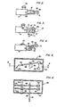
- Fig. 1 discloses a hammer drill having a handle 1 and a motor compartment 2.
- the forward part of the drill, shown broken away at 4 would contain the percussion mechanism of the drill.
- a universal motor 6 is held in the motor compartment 2 in clam-shell fashion by two halves of the compartment 2.
- An actuating lever 12 extends between the upper portion of the trigger 10 and the lower portion of the motor compartment 2 and is pivotally attached to the body of the main switch 8.
- Electric leads 14, 16 supply the main switch 8 with line voltage when the drill is connected to the source of line voltage.
- Electric leads 18, 20 connect the main switch 8 to the motor compartment 2.
- a speed control dial 22 which operates through speed control circuitry in a compartment 24 for controlling the speed of the drill.
- the motor 6 has an armature 26 with a commutator 28, one end of the armature being jour- naled in a bearing 30 and the other end of the armature 26 being drivingly connected to a drive shaft 32.
- the universal motor 6 has a stator assembly 34 and two sets of field windings, only one of which 36 can be seen in Fig. 1.
- the stator assembly has a stator lamination stack 38 defining two poles upon which the respective field windings are wound.
- a printed-circuit board assembly 40 is mounted in the motor compartment 2 and comprises a printed-circuit board 42 having mounted thereon brass brush holders 44 containing carbon brushes 46 which are urged by springs in contact with the commutator 28.
- a pair of plug terminals 48 extend from the rear of the printed-circuit board for connecting to the brushes 46.
- a reversing switch 50 for reversing the direction of drive. of the motor 6, is mounted on the circuit board 42 by means of a housing-like structure 138, and is disposed between the board 42 and the stator assembly 34.
- a pin 52 by which the switch 50 is actuated, extends downwardly through a slot 54 in the lower wall of the compartment 2 and engages in the actuating lever 12.
- a banana-type plug 58 supported from a housing-like structure, extends into a passageway 60 in the upper portion of the stator lamination stack 38.
- a securing pin 62 extends from the reversing switch 50 and engages in another passageway 64 in the lower portion of the stator lamination stack.
- the banana-type plug 58 and the securing pin 62 are close sliding fits in their respective passageways 60, 64 and comprise the main mounting of the printed-circuit board assembly 40 on the stator assembly 34.
- Fig. 2 is a view looking downwards on the switch 8, trigger 10, and actuating lever 12.
- a slot 66 is disposed along the upper portion of the actuating lever 12 and the lower end of the pin 52 slidably engages in the slot 66.
- the left hand end of the actuating lever 12 is attached by a pivot pin 68 to the underside of the upper wall of the switch 8.
- a locking button 70 protrudes from the side of the switch 8 and functions in known manner to releasably hold the trigger 10 in its operating position when the button 70 is depressed.
- Fig. 3 is a diagrammatic view looking down on the switch 8 and trigger 10 just below the actuating lever 12 which is shown in broken lines.
- the trigger 10 is formed at its outer raised end 71 (see Fig. 1) with a short central partition 72 and two outer thin flanges 74, which together form two open ended grooves 76, 78.
- a web-like detent 80 is formed on the lower side of the actuating lever 12 (see Fig. 1).
- the partition 72 has an inner endface 82 which in the neutral central position of the actuating lever 12, as shown in Fig. 3, is disposed in line with an opposite detent 80. In this position the detent 80 prevents the trigger 10 from being squeezed inwards of the handle 1 to actuate the switch 8, i.e., in this position, the switch 8 is in the "off" position and the drill cannot be energized.
- Fig. 4 is a similar view to Fig. 2 but with the detent 80 and partition 72 shown in broken lines, and also with the actuating lever 12 pivoted sideways.
- the trigger 10 has now been moved inwardly into an operative position to energize the drill and the detent 80 has slid into the groove 76, at the same time the pin 52 of the reversing switch 50 has been moved by the slot 66 to operate the switch 50 to allow the motor 6 to be energized to drivingly rotate in one direction.
- the switch 50 remains in a neutral position in which the motor 6 cannot be energized.
- the trigger 10 cannot be operated to actuate the switch 8 until the lever 12 has been pivoted to one side, thereafter the inward movement of the trigger 10 to actuate the switch 8 causes the endface 82 of the partition 72 to engage a side of the detent 80 and cause the lever 12 to be pivoted a sufficient amount to ensure full operation of the switch 50.
- the trigger 10 is released to de-energize the drill and then the lever 12 is pivoted back through its central position to the opposite side of the trigger 10. Then, when the trigger 10 is again actuated, the detent 80 will slidably engage in the other groove 78.
- the switch 50 has a housing 84 of insulating material in which are pivotally mounted two parallel spaced apart contact arms 86, 88.
- the arms 86, 88 are pivotally supported by a pivot pin 90 of insulating material secured to the housing 84.
- the housing 84 contains four U-shaped spring contacts which are engageable by the outer ends of the contact arms 86, 88.
- Fig. 5 shows the lower contact arm 86 engaged in one of the contacts 92. When the arm 86 is pivoted to the other side of the switch 50 its end disengages from the contact 92 and engages another one of the contacts 96.
- the bottom of the switch 50 has a semi-circular aperture 98 through which the pin 52, which is secured to both the contact arms 86, 88, passes downwardly.
- the pin 52 is made from insulating material.
- the upper contact arm 88 engages at its outer end in another of the contacts 94.
- Electric leads 100, 102 are connected to the opposite ends of the arms 86, 88.
- the switch 50 is a double pole switch actuated by the movement of the pin 52.
- the contact arms 86, 88 will be disengaged from either pair of U-shaped contacts, 92, 94 being one such pair, so placing the switch in an off position.
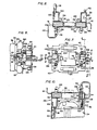
- Fig. 7 is a view of the printed-circuit board assembly 40 in the direction 7-7 Fig. 1. However, it should be noted that the assembly 40 has been rotated through an angle of 90° anti-clockwise from the position in Fig. 1. Thus it will be seen that the pin 52 is on the right hand side in Fig. 7 instead of being at the bottom.
- the assembly is mounted on the printed-circuit board 42 which has a central rectangular cutout 104 forming an- aperture through which commutator 28 is located (see Fig. 1). Leads 18, 20 from the main switch 8 supply the printed-circuit which is on the underside of the printed-circuit board 42.
- Fig. 1 the printed-circuit board assembly 40 in the direction 7-7 Fig. 1. However, it should be noted that the assembly 40 has been rotated through an angle of 90° anti-clockwise from the position in Fig. 1. Thus it will be seen that the pin 52 is on the right hand side in Fig. 7 instead of being at the bottom.
- the assembly is mounted on the printed-circuit
- the assembly 40 includes components of noise suppression circuitry of which is shown two noise suppression coils 122 and 124.
- the printed-circuit board assembly 40 is equipped with two housing-like structures, 136, 138, made of plastics material, which support the assembly on the end face of the lamination stator stack, while at the same time, holding it in spaced relation to that end face.
- Each of the housings 136, 138 has mounted thereon two field coil plug terminals an accommodates a brush holder.
- .e lower housing-like structure 138 includes a compartment wherein the reversing switch 50 is mounted.
- Fig. 11 is a schematic circuit diagram showing the connection of the components described and two additional components.
- Line voltage applied across 139 is carried by leads 14, 16 to the main switch 8, thence through leads 18, 20 to field coil plug terminals 114, 120. Then through field coil windings 36, 131 to field coil plug terminals 118, 116 and to the reversing switch 50.
- the brushes 46 are connected in one configuration to rotate the commutator 28 in one direction.
- the brushes 46 are connected in a configuration that rotates the commutator 28 in the opposite direction.
- the noise suppression coils 122, 124 are connected between the reversing switch 50 and the brushes 46.
- a delta capacitor arrangement 140 for noise suppression is connected across leads 18, 20 and has an earth ground to the lamination stator stack by the banana plug 58.
- the delta capacitor arrangement 140 is mounted in the motor housing but not on the printed-circuit board assembly.
- a triac 142 symbolizing the speed-control electronics is mounted in the compartment 24 (see Fig. 1).
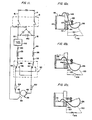
- Figs. 12 a, b, and c depict schematically an additional feature of the printed-circuit :aoard assembly 40 for automatically de-energizing the motor 6 and rendering the portable tool inoperative before worn brushes 46 cause damage to the commutator 28.
- Fig. 12a shows the position of a brush 46 when new in the brush holder 44 with the spring 126, one end of which is connected on the bracket 129, urging the brush 46 downwards.
- the printed-circuit board 42 has a cutout 149 therein to accommodate movement of the spring 126.
- the cutout 149 has a bottom edge 147.
- a conductor strip 144 on the printed-circuit board terminates in a contact 146 at the edge 147.
- the conductor strip 144 is connected by circuitry, schamatically shown by broken lines 150, to the metal spring 126, this circuitry including a motor cutoff switch 148.
- circuitry schamatically shown by broken lines 150
- the spring 126 is clear of the contact 146.
- Fig. 12b shows the position of the brush 46 when about halfway through its useful life, and again there is still a clearance between the contact 146 and the spring 126.
- Fig. 12c shows the position of the brush 46 when it is worn out and needs replacing before damaging the commutator.
- the spring 126 has been arranged to make contact with the contact 146 so energizing the circuitry 150 to effect closing the motor cutoff switch 148 to de-energize the motor 6, so preventing any damage to the commutator.
- the printed circuit board assembly is a compact module carrying the brush holders with their brushes and springs, the field coil terminal connections, the brush lead connections, noise suppression circuitry components, and the motor reversing switch 50.
- the assembly 40 is readily and simply mounted on the stator lamination stack by inserting the banana-plug 58 and the securing pin 62 in their respective passageways 60, 64, at the same time the four field coil plug terminals 114, 116, 118, 120, insert into receptacle terminals (not shown) in the coil retaining end plate 130 as explained above. It should be noted that of the above six mechanical connections of the printed-circuit board assembly 40 to the stator assembly 34, only one, namely securing pin 62, does not serve an electrical connection function.
- the banana plug 58 serves as an earth connection.
- the complete motor module including the stator assembly 34, the armature 26, and the printed-circuit board assembly 40 can be assembled in advance and then placed into a clam-shell housing half of the motor housing 2 whilst on the assembly line.
- Figs. 13, 14, and 15 show diagrammatically a modification of the mechanism for operating the reversing switch and the interrelation with the main switch.
- Fig. 13 is a similar view to Fig. 1, but only showing the necessary parts to illustrate the modification.
- Part of the handle 1, and part of the lower wall of the motor compartment 2 are shown together with the lower portion of the printed-circuit board assembly 40 having the brush 46, the reversing switch 50, and its actuating pin 52.
- the main switch 8a and its trigger 10a are similar to those shown in Fig. 1.
- a lever-like member 152, mounted inside the motor housing 2, has a pivot 154 at one end pivotally mounted in a bracket 156 in the motor compartment.
- a downward projection 158 which engages in a cavity 160 of a slide member 162.
- the slide member 162 has a pair of oppositely opposed grooves 164 therein which slidably engage reduced lips 166 which define the periphery of an arcuate slot 168 (see Fig. 14) through the bottom wall of the motor compartment 2 at a location forward of and adjacent to the trigger 10a.
- a hole 169 therethrough which is engaged by the reversing switch pin 52.
- the lever 152 Near its inner end, the lever 152 has a downwardly projecting pin-like detent 170 which interrelates with the trigger 10a.
- Fig. 15 shows the upper part of the trigger 10a having two thin side walls 172 and a shorter central partition 174 which between them define two grooves 176, 178.
- the central partition 174 has an end edge 175 which engages the pin-like detent 170 when the latter is in a central position (corresponding to the position of the slide member 162 in Fig. 14) to prevent the trigger 10a being moved inwardly, and so rendering the main switch 8a inoperative.
- the reversing switch pin 52 is moved along the arc 182 to actuate the reversing switch 50.
- the pin-like detent 170 moves along the arc 184 to one of the positions shown in phantom lines. This then allows the trigger 10a to be operated with the pin 170 entering either the groove 176 or the groove 178.
- the detent pin 170 performs the same function as the detent 80 in Fig. 3.
- the reversing switch pin 52 engages the pivoted lever 152 within the motor compartment 2.
- the only portion of the means interrelating the reversing switch and the main switch that is accessible from the exterior of the motor compartment 2 is the protruding part of the slide 162 by which the reversing switch is operated.
- the reversing switch constitutes a discrete integral component. It is neatly mounted directly on printed-circuit board and is mechanically coupled directly to the manually- manipulatable reversing member so as to reduce the required wiring into the handle and simplify the overall assembly.
- actuating lever 12 in Fig. 1 could be pivotally attached to the underside of the motor housing 2.
- any convenient type of double pole switch having two actuation positions and a neutral position could be used for the reversing switch 50.
Landscapes
- Dc Machiner (AREA)
- Scissors And Nippers (AREA)
- Push-Button Switches (AREA)
- Portable Power Tools In General (AREA)
Abstract
Description
- The invention relates to a portable electric tool having a housing with a handle, a motor compartment and a reversible motor contained in the motor compartment, a switch mounted as a component on a printed-circuit board in the motor compartment, which printed-circuit board is mechanically plugged onto the stator of the motor with a part of the armature extending through an aperture in the printed-circuit board.
- In document EP-Al-0 025 938, which falls under the terms of Article 54(3)EPC, a portable electric tool is described in which a printed-circuit board is plugged onto its stator so that a part of the armature of the motor extends through an aperture in the printed-circuit board. On the printed-circuit board a switch is mounted, which switch is the main switch for energizing the electric motor of the portable tool.
- DE-Al-2 631 431 describes a portable electric tool using a printed-circuit board on which the main switch is mounted. Although it is mentioned that the printed-circuit board is suitable to be plugged there is no indication as to the element to be connected with the printed-circuit board by plugging of such board. The main switch of such portable electric tool is located in the handle and the tool does not permit reversing of its direction of rotation.
- It is an object of the invention to provide a portable electric tool with a reversing switch to change the direction of rotation of its motor and to obtain a compact arrangement with an exactly positioned printed-circuit board.
- The invention therefore provides for a portable electric tool of the above-mentioned type, which tool is characterized in that the switch mounted on the printed-circuit board is a reversing switch for determining the direction of rotation of the motor, which reversing switch is mechanically coupled with an actuating member located adjacent to a main switch in the handle for energizing the motor, wherein the reversing switch and the main switch are mechanically interrelated to render the main switch inoperative until the reversing switch is actuated, and in that at least one securing pin slidably engaged in a passage-way in the stator is mounted on the printed-circuit board.
- Positioning the reversing switch on the printed-circuit board in the motor compartment enables the number of wires needed between the main switch and the motor compartment to be at least two less than would otherwise be required, whereas the mechanical interrelation of the reversing switch and the main switch avoids actuation of the reversing switch when the main switch is actuated so that the reversing switch can only be actuated when the motor is not energized. By providing for at least one securing pin the printed-circuit board can be mounted on the stator in a defined position, whereas mounting of the printed-circuit board on the stator by means of electric connector members provided on the - printed-circuit board and the stator (EP-Al-0 025 938) would either require relatively rigid and therefore expensive electric connector members or may result in a somewhat indefinite position of the printed-circuit board in relation to the stator.
- Use of a reversing switch and a main switch both mechanically coupled in portable electric tools is known (DE-B2-2 631 994, DE-Al-2 755 960, GB-A-1 128 666). However, in such portable electric tools no printed-circuit boards are provided.
- The invention will now be described in greater detail with reference to the drawings, which shown preferred embodiments.
- Fig. 1 is a diagrammatic vertical section of part of a hammer drill according to the present inven- ' tion;
- Fig. 2 is a diagrammatic view on the line 2-2 in Fig. 1 of a component;
- Fig. 3 is a diagrammatic view on the line 3-3 in Fig. 1 of a component;
- Fig. 4 is a similar view to Fig. 2 with the component in a different operating position;
- Fig. 5 is a diagrammatic section on the line 5-5 of Fig. 1 of another component;
- Fig. 6 is a section on the line 6-6 of Fig. 5;
- Fig. 7 is a view on the line 7-7 of Fig. 1 of a printed-circuit board module according to the invention;
- Fig. 8 is a section on the line 8-8 of Fig. 7;
- Fig. 9 is a section on the line 9-9 in Fig. 7;
- Fig. 10 is a section on the line 10-10 in Fig. 7;
- Fig. 11 is a schematic circuit diagram;
- Figs. 12a, b and c show diagrammatically a section through a brush holder with the brush in different positions;
- Fig. 13 is a similar section to Fig. 1 showing a modification of the hammer drill;
- Fig. 14 is a bottom view on the line 14-14 in Fig. 13; and
- Fig. 15 is a diagrammatic section on the line 15-15 in Fig. 13.
- Fig. 1 discloses a hammer drill having a handle 1 and a
motor compartment 2. The forward part of the drill, shown broken away at 4 would contain the percussion mechanism of the drill. Auniversal motor 6 is held in themotor compartment 2 in clam-shell fashion by two halves of thecompartment 2. In the handle 1 is mounted amain switch 8 by which the tool is energized, theswitch 8 being actuated by atrigger 10 in a known manner. An actuatinglever 12 extends between the upper portion of thetrigger 10 and the lower portion of themotor compartment 2 and is pivotally attached to the body of themain switch 8. Electric leads 14, 16 supply themain switch 8 with line voltage when the drill is connected to the source of line voltage. Electric leads 18, 20 connect themain switch 8 to themotor compartment 2. It will be noticed that only a portion ofleads compartment 2 is mounted aspeed control dial 22 which operates through speed control circuitry in acompartment 24 for controlling the speed of the drill. Themotor 6 has anarmature 26 with acommutator 28, one end of the armature being jour- naled in abearing 30 and the other end of thearmature 26 being drivingly connected to adrive shaft 32. Theuniversal motor 6 has astator assembly 34 and two sets of field windings, only one of which 36 can be seen in Fig. 1. The stator assembly has astator lamination stack 38 defining two poles upon which the respective field windings are wound. _ _ _ _ - A printed-
circuit board assembly 40 is mounted in themotor compartment 2 and comprises a printed-circuit board 42 having mounted thereonbrass brush holders 44 containingcarbon brushes 46 which are urged by springs in contact with thecommutator 28. A pair ofplug terminals 48 extend from the rear of the printed-circuit board for connecting to thebrushes 46. A reversing switch 50, for reversing the direction of drive. of themotor 6, is mounted on thecircuit board 42 by means of a housing-like structure 138, and is disposed between theboard 42 and thestator assembly 34. Apin 52, by which theswitch 50 is actuated, extends downwardly through aslot 54 in the lower wall of thecompartment 2 and engages in the actuatinglever 12. A banana-type plug 58, supported from a housing-like structure, extends into apassageway 60 in the upper portion of thestator lamination stack 38. Asecuring pin 62 extends from thereversing switch 50 and engages in anotherpassageway 64 in the lower portion of the stator lamination stack. The banana-type plug 58 and the securingpin 62 are close sliding fits in theirrespective passageways circuit board assembly 40 on thestator assembly 34. - Fig. 2 is a view looking downwards on the
switch 8, trigger 10, and actuatinglever 12. Aslot 66 is disposed along the upper portion of the actuatinglever 12 and the lower end of thepin 52 slidably engages in theslot 66. The left hand end of the actuatinglever 12 is attached by apivot pin 68 to the underside of the upper wall of theswitch 8. Alocking button 70 protrudes from the side of theswitch 8 and functions in known manner to releasably hold thetrigger 10 in its operating position when thebutton 70 is depressed. - Fig. 3 is a diagrammatic view looking down on the
switch 8 and trigger 10 just below the actuatinglever 12 which is shown in broken lines. Thetrigger 10 is formed at its outer raised end 71 (see Fig. 1) with a shortcentral partition 72 and two outerthin flanges 74, which together form two openended grooves like detent 80 is formed on the lower side of the actuating lever 12 (see Fig. 1). Thepartition 72 has aninner endface 82 which in the neutral central position of the actuatinglever 12, as shown in Fig. 3, is disposed in line with anopposite detent 80. In this position the detent 80 prevents thetrigger 10 from being squeezed inwards of the handle 1 to actuate theswitch 8, i.e., in this position, theswitch 8 is in the "off" position and the drill cannot be energized. - Fig. 4 is a similar view to Fig. 2 but with the detent 80 and
partition 72 shown in broken lines, and also with the actuatinglever 12 pivoted sideways. As can be seen, thetrigger 10 has now been moved inwardly into an operative position to energize the drill and thedetent 80 has slid into thegroove 76, at the same time thepin 52 of thereversing switch 50 has been moved by theslot 66 to operate theswitch 50 to allow themotor 6 to be energized to drivingly rotate in one direction. When the actuatinglever 12 is in the central position shown in Figs. 2 and 3, theswitch 50 remains in a neutral position in which themotor 6 cannot be energized. It should be noted that although thetrigger 10 cannot be operated to actuate theswitch 8 until thelever 12 has been pivoted to one side, thereafter the inward movement of thetrigger 10 to actuate theswitch 8 causes theendface 82 of thepartition 72 to engage a side of thedetent 80 and cause thelever 12 to be pivoted a sufficient amount to ensure full operation of theswitch 50. To reverse the direction of drive of'themotor 6 from the direction determined by the position of thelever 12 in Fig. 4, thetrigger 10 is released to de-energize the drill and then thelever 12 is pivoted back through its central position to the opposite side of thetrigger 10. Then, when thetrigger 10 is again actuated, thedetent 80 will slidably engage in theother groove 78. - Referring to Figs. 5 and 6 the
switch 50 has ahousing 84 of insulating material in which are pivotally mounted two parallel spaced apart contactarms arms pivot pin 90 of insulating material secured to thehousing 84. Thehousing 84 contains four U-shaped spring contacts which are engageable by the outer ends of thecontact arms lower contact arm 86 engaged in one of thecontacts 92. When thearm 86 is pivoted to the other side of theswitch 50 its end disengages from thecontact 92 and engages another one of thecontacts 96. The bottom of theswitch 50 has asemi-circular aperture 98 through which thepin 52, which is secured to both thecontact arms pin 52 is made from insulating material. As can be seen in Fig. 6, theupper contact arm 88 engages at its outer end in another of thecontacts 94. Electric leads 100, 102 are connected to the opposite ends of thearms switch 50 is a double pole switch actuated by the movement of thepin 52. As can be realized from Fig. 5, when thepin 52 is in a central position, as shown in Fig. 2, thecontact arms - Fig. 7 is a view of the printed-
circuit board assembly 40 in the direction 7-7 Fig. 1. However, it should be noted that theassembly 40 has been rotated through an angle of 90° anti-clockwise from the position in Fig. 1. Thus it will be seen that thepin 52 is on the right hand side in Fig. 7 instead of being at the bottom. The assembly is mounted on the printed-circuit board 42 which has a centralrectangular cutout 104 forming an- aperture through whichcommutator 28 is located (see Fig. 1). Leads 18, 20 from themain switch 8 supply the printed-circuit which is on the underside of the printed-circuit board 42. In Fig. 7 the upper half of asupport compartment 103 for the banana-type plug 58, and the upper half of theswitch housing 84 are diagrammatically shown in section, so that only half of an end view of thebanana plug 58 and of the securingpin 62 is shown. The two carbon brushes 46 protrude inwardly of theaperture 104 and are connected to brush leads 110, 112. Four fieldcoil plug terminals board 42. Theassembly 40 includes components of noise suppression circuitry of which is shown two noise suppression coils 122 and 124. - Fig. 8 shows schematically brush springs 126 for resiliently urging the carbon brushes 46 inwards. An
earth connection 128 for thebanana plug 58 is housed in thecompartment 103. Only one of theplug terminals 48 for the brushes is shown extending rearwardly from the printed-circuit board 42. The other such terminal 48 has been omitted to show abracket 129, that would otherwise be hidden, to which the free end of thebrush spring 126 is attached. Thebrush lead 112, which is connected to thebrush 46 at one end, has a male connection on the other end which plugs into the terminal 48. - Fig. 9 is a section on the stepped line 9-9 of Fig. 7 and is a representation of the printed-
circuit board assembly 40 attached to thestator 34 as viewed from underneath the drill and turned around through 180° from the position in Fig. 1. A coil retaining plastic end plate, 130, attached to the end face of thestator lamination stack 38, retains the end turns of the field winding 36, and the end turns of a second field winding 131. The two ends of each field winding wire are connected to respective receptacle terminals. These terminals are seated in respective bores of theend plate 130. The field coil plug terminals 114,118 of the printed-circuit board assembly engage in receptacle terminals in said bores of theend plate 130 corresponding to one of the fields. Likewise, the fieldcoil plug terminals brush lead 110 is connected to its respective brush via a connector 111. - Fig. 10 is a view on the stepped line 10-10 of Fig. 7 and also shows the attachment of the printed-
circuit board assembly 40 to thestator 34. Aplug connection 132 for a lead to theswitch 50 is shown. - It will be appreciated from Figs. 7 through 10, and also Fig. 1, that the printed-
circuit board assembly 40 is equipped with two housing-like structures, 136, 138, made of plastics material, which support the assembly on the end face of the lamination stator stack, while at the same time, holding it in spaced relation to that end face. Each of thehousings like structure 138 includes a compartment wherein the reversingswitch 50 is mounted. - Fig. 11 is a schematic circuit diagram showing the connection of the components described and two additional components. Line voltage applied across 139 is carried by
leads main switch 8, thence through leads 18, 20 to fieldcoil plug terminals field coil windings coil plug terminals switch 50. As shown with thecontact arm 88 engagingcontact 94 andcontact arm 86 engagingcontact 92, thebrushes 46 are connected in one configuration to rotate thecommutator 28 in one direction. When thecontact arms brushes 46 are connected in a configuration that rotates thecommutator 28 in the opposite direction. The noise suppression coils 122, 124 are connected between the reversingswitch 50 and thebrushes 46. Adelta capacitor arrangement 140 for noise suppression is connected across leads 18, 20 and has an earth ground to the lamination stator stack by thebanana plug 58. Thedelta capacitor arrangement 140 is mounted in the motor housing but not on the printed-circuit board assembly. Atriac 142 symbolizing the speed-control electronics is mounted in the compartment 24 (see Fig. 1). - Figs. 12 a, b, and c depict schematically an additional feature of the printed-circuit :
aoard assembly 40 for automatically de-energizing themotor 6 and rendering the portable tool inoperative before worn brushes 46 cause damage to thecommutator 28. Fig. 12a shows the position of abrush 46 when new in thebrush holder 44 with thespring 126, one end of which is connected on thebracket 129, urging thebrush 46 downwards. The printed-circuit board 42 has acutout 149 therein to accommodate movement of thespring 126. Thecutout 149 has abottom edge 147. Aconductor strip 144 on the printed-circuit board terminates in acontact 146 at theedge 147. Theconductor strip 144 is connected by circuitry, schamatically shown bybroken lines 150, to themetal spring 126, this circuitry including amotor cutoff switch 148. As can be seen in Fig. 12a, with anew brush 46, thespring 126 is clear of thecontact 146. Fig. 12b shows the position of thebrush 46 when about halfway through its useful life, and again there is still a clearance between thecontact 146 and thespring 126. Fig. 12c shows the position of thebrush 46 when it is worn out and needs replacing before damaging the commutator. As can be seen, in this position of thebrush 46, thespring 126 has been arranged to make contact with thecontact 146 so energizing thecircuitry 150 to effect closing themotor cutoff switch 148 to de-energize themotor 6, so preventing any damage to the commutator. - As can readily be understood, the printed circuit board assembly is a compact module carrying the brush holders with their brushes and springs, the field coil terminal connections, the brush lead connections, noise suppression circuitry components, and the
motor reversing switch 50. Moreover, theassembly 40 is readily and simply mounted on the stator lamination stack by inserting the banana-plug 58 and the securingpin 62 in theirrespective passageways coil plug terminals end plate 130 as explained above. It should be noted that of the above six mechanical connections of the printed-circuit board assembly 40 to thestator assembly 34, only one, namely securingpin 62, does not serve an electrical connection function. Thebanana plug 58 serves as an earth connection. - It should be further noted that by placing the reversing
switch 50 in theassembly 40 inside themotor compartment 2, a second set of wires from the trigger-switch 8 is eliminated. Also, the number of electrical connections that have to be made during assembly of the drill is reduced, and with the arrangement of theassembly 40, substantially simplified. - Furthermore, the complete motor module, including the
stator assembly 34, thearmature 26, and the printed-circuit board assembly 40 can be assembled in advance and then placed into a clam-shell housing half of themotor housing 2 whilst on the assembly line. - Figs. 13, 14, and 15 show diagrammatically a modification of the mechanism for operating the reversing switch and the interrelation with the main switch. Fig. 13 is a similar view to Fig. 1, but only showing the necessary parts to illustrate the modification. Part of the handle 1, and part of the lower wall of the
motor compartment 2 are shown together with the lower portion of the printed-circuit board assembly 40 having thebrush 46, the reversingswitch 50, and itsactuating pin 52. Themain switch 8a and itstrigger 10a are similar to those shown in Fig. 1. A lever-like member 152, mounted inside themotor housing 2, has apivot 154 at one end pivotally mounted in abracket 156 in the motor compartment. At the other end of themember 152 is adownward projection 158 which engages in acavity 160 of aslide member 162. Theslide member 162 has a pair of oppositely opposedgrooves 164 therein which slidably engage reducedlips 166 which define the periphery of an arcuate slot 168 (see Fig. 14) through the bottom wall of themotor compartment 2 at a location forward of and adjacent to thetrigger 10a. Intermediate the length of thelever 152 and adjacent theprojection 158 is ahole 169 therethrough which is engaged by the reversingswitch pin 52. Near its inner end, thelever 152 has a downwardly projecting pin-like detent 170 which interrelates with thetrigger 10a. - Fig. 15 shows the upper part of the
trigger 10a having twothin side walls 172 and a shortercentral partition 174 which between them define twogrooves central partition 174 has anend edge 175 which engages the pin-like detent 170 when the latter is in a central position (corresponding to the position of theslide member 162 in Fig. 14) to prevent thetrigger 10a being moved inwardly, and so rendering themain switch 8a inoperative. In operation, when the slide member is moved along thearc 180 to either side of the central position, the reversingswitch pin 52 is moved along thearc 182 to actuate the reversingswitch 50. At the same time, the pin-like detent 170 moves along thearc 184 to one of the positions shown in phantom lines. This then allows thetrigger 10a to be operated with thepin 170 entering either thegroove 176 or thegroove 178. As will be appreciated, thedetent pin 170 performs the same function as thedetent 80 in Fig. 3. It should be noted, in this modification, that the reversingswitch pin 52 engages the pivotedlever 152 within themotor compartment 2. Also, the only portion of the means interrelating the reversing switch and the main switch that is accessible from the exterior of themotor compartment 2 is the protruding part of theslide 162 by which the reversing switch is operated. - It will be appreciated that in the above described embodiments, the reversing switch constitutes a discrete integral component. It is neatly mounted directly on printed-circuit board and is mechanically coupled directly to the manually- manipulatable reversing member so as to reduce the required wiring into the handle and simplify the overall assembly.
- Furthermore, the actuating
lever 12 in Fig. 1 could be pivotally attached to the underside of themotor housing 2. Also, any convenient type of double pole switch having two actuation positions and a neutral position could be used for the reversingswitch 50.
Claims (14)
Priority Applications (1)
| Application Number | Priority Date | Filing Date | Title |
|---|---|---|---|
| AT82100535T ATE12852T1 (en) | 1981-01-29 | 1982-01-27 | PRINTED CIRCUIT BOARD AND TRIGGER CIRCUIT ASSEMBLY FOR A PORTABLE ELECTRIC TOOL. |
Applications Claiming Priority (2)
| Application Number | Priority Date | Filing Date | Title |
|---|---|---|---|
| US06/229,452 US4348603A (en) | 1981-01-29 | 1981-01-29 | Printed-circuit board and trigger-switch arrangement for a portable electric tool |
| US229452 | 1994-04-18 |
Publications (3)
| Publication Number | Publication Date |
|---|---|
| EP0057413A2 EP0057413A2 (en) | 1982-08-11 |
| EP0057413A3 EP0057413A3 (en) | 1982-09-22 |
| EP0057413B1 true EP0057413B1 (en) | 1985-04-17 |
Family
ID=22861308
Family Applications (1)
| Application Number | Title | Priority Date | Filing Date |
|---|---|---|---|
| EP82100535A Expired EP0057413B1 (en) | 1981-01-29 | 1982-01-27 | Printed circuit board and trigger-switch arrangement for a portable tool |
Country Status (4)
| Country | Link |
|---|---|
| US (1) | US4348603A (en) |
| EP (1) | EP0057413B1 (en) |
| AT (1) | ATE12852T1 (en) |
| DE (1) | DE3263065D1 (en) |
Families Citing this family (442)
| Publication number | Priority date | Publication date | Assignee | Title |
|---|---|---|---|---|
| JPS5761480A (en) * | 1980-09-26 | 1982-04-13 | Hitachi Koki Kk | Motor tool |
| IT1167500B (en) * | 1981-09-10 | 1987-05-13 | Star Utensili Elett | TRIGGER CONTROL DEVICE FOR AN ELECTRIC SWITCH, IN PARTICULAR FOR PORTABLE ELECTRIC TOOLS |
| US4574471A (en) * | 1983-03-31 | 1986-03-11 | Black & Decker Inc. | Methods of assembling components of an electric motor |
| US4523116A (en) * | 1983-03-31 | 1985-06-11 | Black & Decker, Inc. | Electrical connection system for motors |
| IT8322175U1 (en) * | 1983-06-21 | 1984-12-21 | Black & Decker Inc | Switch device for reversing the direction of a motor, especially for portable power tools |
| DE3413233A1 (en) * | 1984-04-07 | 1985-11-14 | Robert Bosch Gmbh, 7000 Stuttgart | HAND MACHINE TOOL WITH AN ELECTRIC MOTOR |
| DE3524614A1 (en) * | 1985-07-10 | 1987-01-15 | Bosch Gmbh Robert | HANDWARE MACHINE FOR RIGHT AND LEFT ROTATION |
| DE3538939A1 (en) * | 1985-10-31 | 1987-05-07 | Black & Decker Inc | CUP-BASED BEARING BRIDGE |
| USD301871S (en) | 1985-11-26 | 1989-06-27 | Satori Switch Industry Co., Ltd. | Trigger actuated switch |
| NL8800366A (en) * | 1988-02-15 | 1989-09-01 | Emerson Electric Co | BRUSH MOUNTING DEVICE ON REVERSIBLE COLLECTOR MOTOR. |
| US4968922A (en) * | 1988-04-15 | 1990-11-06 | Lucerne Products, Inc. | Reversing switch |
| US4989308A (en) * | 1988-06-20 | 1991-02-05 | Butler Manufacturing Company | Bidirectional roof seaming machine |
| DE3825035B4 (en) * | 1988-07-09 | 2006-11-23 | Flux-Geräte GmbH | Brushless, electrically commutated motor for a drum or a container pump to Betieb on an AC voltage network |
| US4963779A (en) * | 1989-05-15 | 1990-10-16 | Black & Decker, Inc. | Brush holder for an electric motor |
| DE4038786A1 (en) * | 1990-12-05 | 1992-06-11 | Bsg Schalttechnik | DEVICE FOR CONTROLLING OR REGULATING DEVICES SUPPLIED BY BATTERIES |
| US5089729A (en) * | 1991-03-14 | 1992-02-18 | Black & Decker Inc. | Power tool with brush shifting and reversing switch assembly |
| US5684388A (en) * | 1995-07-31 | 1997-11-04 | Emerson Electric Co. | Scroll saw motor/printed circuit board housing with switch lock-out |
| US5869942A (en) * | 1997-03-12 | 1999-02-09 | Itt Automotive Electrical Systems, Inc. | Noise suppression in relay-switched motors |
| DE19909854A1 (en) * | 1998-03-11 | 1999-09-16 | Marquardt Gmbh | Electrical switch, esp. for electric hand tools |
| JP2000233383A (en) * | 1999-02-12 | 2000-08-29 | Makita Corp | Switch mechanism of power tool |
| US6445097B1 (en) * | 1999-12-01 | 2002-09-03 | Milwaukee Electric Tool Corporation | Method for assembling and electrical connector assembly for a power tool |
| DE10034768A1 (en) * | 2000-07-18 | 2002-02-07 | Bosch Gmbh Robert | Combination electric hand tool operating as hammer drill or electric chisel, has pivoted jaw catch mechanism with blocking component in handle |
| US6392373B1 (en) * | 2000-12-06 | 2002-05-21 | Milwaukee Electric Tool Corporation | Automatic reverse motor controller |
| US7116071B2 (en) * | 2000-12-06 | 2006-10-03 | Milwaukee Electric Tool Corporation | Power tool and motor controller |
| DE10259569A1 (en) * | 2002-12-19 | 2004-07-01 | Hilti Ag | Hand-held power tool, e.g. chisel hammer, has sensor switch connected free of vibration with switch carrier |
| US20070084897A1 (en) | 2003-05-20 | 2007-04-19 | Shelton Frederick E Iv | Articulating surgical stapling instrument incorporating a two-piece e-beam firing mechanism |
| US9060770B2 (en) | 2003-05-20 | 2015-06-23 | Ethicon Endo-Surgery, Inc. | Robotically-driven surgical instrument with E-beam driver |
| DE10340178B3 (en) * | 2003-09-01 | 2005-04-07 | Hilti Ag | power tool |
| US7138595B2 (en) * | 2004-04-02 | 2006-11-21 | Black & Decker Inc. | Trigger configuration for a power tool |
| US11998198B2 (en) | 2004-07-28 | 2024-06-04 | Cilag Gmbh International | Surgical stapling instrument incorporating a two-piece E-beam firing mechanism |
| US11890012B2 (en) | 2004-07-28 | 2024-02-06 | Cilag Gmbh International | Staple cartridge comprising cartridge body and attached support |
| US9072535B2 (en) | 2011-05-27 | 2015-07-07 | Ethicon Endo-Surgery, Inc. | Surgical stapling instruments with rotatable staple deployment arrangements |
| US8215531B2 (en) | 2004-07-28 | 2012-07-10 | Ethicon Endo-Surgery, Inc. | Surgical stapling instrument having a medical substance dispenser |
| DE102004051913A1 (en) † | 2004-08-09 | 2006-02-23 | Robert Bosch Gmbh | Cordless Screwdriver |
| US11246590B2 (en) | 2005-08-31 | 2022-02-15 | Cilag Gmbh International | Staple cartridge including staple drivers having different unfired heights |
| US9237891B2 (en) | 2005-08-31 | 2016-01-19 | Ethicon Endo-Surgery, Inc. | Robotically-controlled surgical stapling devices that produce formed staples having different lengths |
| US7669746B2 (en) | 2005-08-31 | 2010-03-02 | Ethicon Endo-Surgery, Inc. | Staple cartridges for forming staples having differing formed staple heights |
| US10159482B2 (en) | 2005-08-31 | 2018-12-25 | Ethicon Llc | Fastener cartridge assembly comprising a fixed anvil and different staple heights |
| US11484312B2 (en) | 2005-08-31 | 2022-11-01 | Cilag Gmbh International | Staple cartridge comprising a staple driver arrangement |
| US7934630B2 (en) | 2005-08-31 | 2011-05-03 | Ethicon Endo-Surgery, Inc. | Staple cartridges for forming staples having differing formed staple heights |
| US8657031B2 (en) * | 2005-10-12 | 2014-02-25 | Black & Decker Inc. | Universal control module |
| US20070106317A1 (en) | 2005-11-09 | 2007-05-10 | Shelton Frederick E Iv | Hydraulically and electrically actuated articulation joints for surgical instruments |
| USD580725S1 (en) | 2006-01-06 | 2008-11-18 | Milwaukee Electric Tool Corporation | Power tool, such as a drill |
| US8186555B2 (en) | 2006-01-31 | 2012-05-29 | Ethicon Endo-Surgery, Inc. | Motor-driven surgical cutting and fastening instrument with mechanical closure system |
| US11224427B2 (en) | 2006-01-31 | 2022-01-18 | Cilag Gmbh International | Surgical stapling system including a console and retraction assembly |
| US20110024477A1 (en) | 2009-02-06 | 2011-02-03 | Hall Steven G | Driven Surgical Stapler Improvements |
| US8708213B2 (en) | 2006-01-31 | 2014-04-29 | Ethicon Endo-Surgery, Inc. | Surgical instrument having a feedback system |
| US11793518B2 (en) | 2006-01-31 | 2023-10-24 | Cilag Gmbh International | Powered surgical instruments with firing system lockout arrangements |
| US8820603B2 (en) | 2006-01-31 | 2014-09-02 | Ethicon Endo-Surgery, Inc. | Accessing data stored in a memory of a surgical instrument |
| US20110295295A1 (en) | 2006-01-31 | 2011-12-01 | Ethicon Endo-Surgery, Inc. | Robotically-controlled surgical instrument having recording capabilities |
| US20120292367A1 (en) | 2006-01-31 | 2012-11-22 | Ethicon Endo-Surgery, Inc. | Robotically-controlled end effector |
| US11278279B2 (en) | 2006-01-31 | 2022-03-22 | Cilag Gmbh International | Surgical instrument assembly |
| US7753904B2 (en) | 2006-01-31 | 2010-07-13 | Ethicon Endo-Surgery, Inc. | Endoscopic surgical instrument with a handle that can articulate with respect to the shaft |
| US7845537B2 (en) | 2006-01-31 | 2010-12-07 | Ethicon Endo-Surgery, Inc. | Surgical instrument having recording capabilities |
| US8992422B2 (en) | 2006-03-23 | 2015-03-31 | Ethicon Endo-Surgery, Inc. | Robotically-controlled endoscopic accessory channel |
| DE102006000161A1 (en) * | 2006-04-06 | 2007-10-11 | Hilti Ag | Carbon holder device |
| USD564321S1 (en) | 2006-04-12 | 2008-03-18 | Professional Tool Products, Llc | Portion of a housing for a rotary tool |
| US8322455B2 (en) | 2006-06-27 | 2012-12-04 | Ethicon Endo-Surgery, Inc. | Manually driven surgical cutting and fastening instrument |
| US10568652B2 (en) | 2006-09-29 | 2020-02-25 | Ethicon Llc | Surgical staples having attached drivers of different heights and stapling instruments for deploying the same |
| US11980366B2 (en) | 2006-10-03 | 2024-05-14 | Cilag Gmbh International | Surgical instrument |
| US8632535B2 (en) | 2007-01-10 | 2014-01-21 | Ethicon Endo-Surgery, Inc. | Interlock and surgical instrument including same |
| US11291441B2 (en) | 2007-01-10 | 2022-04-05 | Cilag Gmbh International | Surgical instrument with wireless communication between control unit and remote sensor |
| US8684253B2 (en) | 2007-01-10 | 2014-04-01 | Ethicon Endo-Surgery, Inc. | Surgical instrument with wireless communication between a control unit of a robotic system and remote sensor |
| US8701958B2 (en) | 2007-01-11 | 2014-04-22 | Ethicon Endo-Surgery, Inc. | Curved end effector for a surgical stapling device |
| US11039836B2 (en) | 2007-01-11 | 2021-06-22 | Cilag Gmbh International | Staple cartridge for use with a surgical stapling instrument |
| CN101256910B (en) * | 2007-03-01 | 2011-05-18 | 苏州宝时得电动工具有限公司 | Switch of electric tool and electric tool using the switch |
| US8727197B2 (en) | 2007-03-15 | 2014-05-20 | Ethicon Endo-Surgery, Inc. | Staple cartridge cavity configuration with cooperative surgical staple |
| US8931682B2 (en) | 2007-06-04 | 2015-01-13 | Ethicon Endo-Surgery, Inc. | Robotically-controlled shaft based rotary drive systems for surgical instruments |
| US11857181B2 (en) | 2007-06-04 | 2024-01-02 | Cilag Gmbh International | Robotically-controlled shaft based rotary drive systems for surgical instruments |
| US7753245B2 (en) | 2007-06-22 | 2010-07-13 | Ethicon Endo-Surgery, Inc. | Surgical stapling instruments |
| US11849941B2 (en) | 2007-06-29 | 2023-12-26 | Cilag Gmbh International | Staple cartridge having staple cavities extending at a transverse angle relative to a longitudinal cartridge axis |
| US7819298B2 (en) | 2008-02-14 | 2010-10-26 | Ethicon Endo-Surgery, Inc. | Surgical stapling apparatus with control features operable with one hand |
| US8573465B2 (en) | 2008-02-14 | 2013-11-05 | Ethicon Endo-Surgery, Inc. | Robotically-controlled surgical end effector system with rotary actuated closure systems |
| BRPI0901282A2 (en) | 2008-02-14 | 2009-11-17 | Ethicon Endo Surgery Inc | surgical cutting and fixation instrument with rf electrodes |
| US9179912B2 (en) | 2008-02-14 | 2015-11-10 | Ethicon Endo-Surgery, Inc. | Robotically-controlled motorized surgical cutting and fastening instrument |
| US11986183B2 (en) | 2008-02-14 | 2024-05-21 | Cilag Gmbh International | Surgical cutting and fastening instrument comprising a plurality of sensors to measure an electrical parameter |
| US8758391B2 (en) | 2008-02-14 | 2014-06-24 | Ethicon Endo-Surgery, Inc. | Interchangeable tools for surgical instruments |
| US8636736B2 (en) | 2008-02-14 | 2014-01-28 | Ethicon Endo-Surgery, Inc. | Motorized surgical cutting and fastening instrument |
| US7866527B2 (en) | 2008-02-14 | 2011-01-11 | Ethicon Endo-Surgery, Inc. | Surgical stapling apparatus with interlockable firing system |
| US10390823B2 (en) | 2008-02-15 | 2019-08-27 | Ethicon Llc | End effector comprising an adjunct |
| US8210411B2 (en) | 2008-09-23 | 2012-07-03 | Ethicon Endo-Surgery, Inc. | Motor-driven surgical cutting instrument |
| US9386983B2 (en) | 2008-09-23 | 2016-07-12 | Ethicon Endo-Surgery, Llc | Robotically-controlled motorized surgical instrument |
| US9005230B2 (en) | 2008-09-23 | 2015-04-14 | Ethicon Endo-Surgery, Inc. | Motorized surgical instrument |
| US11648005B2 (en) | 2008-09-23 | 2023-05-16 | Cilag Gmbh International | Robotically-controlled motorized surgical instrument with an end effector |
| US8608045B2 (en) | 2008-10-10 | 2013-12-17 | Ethicon Endo-Sugery, Inc. | Powered surgical cutting and stapling apparatus with manually retractable firing system |
| US8517239B2 (en) | 2009-02-05 | 2013-08-27 | Ethicon Endo-Surgery, Inc. | Surgical stapling instrument comprising a magnetic element driver |
| AU2010210795A1 (en) | 2009-02-06 | 2011-08-25 | Ethicon Endo-Surgery, Inc. | Driven surgical stapler improvements |
| US8552615B2 (en) * | 2009-06-17 | 2013-10-08 | Black & Decker Inc. | Electric motors having EMI reducing circuits and methods therefor |
| CN101651396B (en) * | 2009-09-23 | 2012-05-23 | 杭州天铭机电工具有限公司 | Direct current motor |
| US8851354B2 (en) | 2009-12-24 | 2014-10-07 | Ethicon Endo-Surgery, Inc. | Surgical cutting instrument that analyzes tissue thickness |
| US8220688B2 (en) | 2009-12-24 | 2012-07-17 | Ethicon Endo-Surgery, Inc. | Motor-driven surgical cutting instrument with electric actuator directional control assembly |
| US8783543B2 (en) | 2010-07-30 | 2014-07-22 | Ethicon Endo-Surgery, Inc. | Tissue acquisition arrangements and methods for surgical stapling devices |
| US8978954B2 (en) | 2010-09-30 | 2015-03-17 | Ethicon Endo-Surgery, Inc. | Staple cartridge comprising an adjustable distal portion |
| US11812965B2 (en) | 2010-09-30 | 2023-11-14 | Cilag Gmbh International | Layer of material for a surgical end effector |
| US9629814B2 (en) | 2010-09-30 | 2017-04-25 | Ethicon Endo-Surgery, Llc | Tissue thickness compensator configured to redistribute compressive forces |
| US9386988B2 (en) | 2010-09-30 | 2016-07-12 | Ethicon End-Surgery, LLC | Retainer assembly including a tissue thickness compensator |
| US12213666B2 (en) | 2010-09-30 | 2025-02-04 | Cilag Gmbh International | Tissue thickness compensator comprising layers |
| US9839420B2 (en) | 2010-09-30 | 2017-12-12 | Ethicon Llc | Tissue thickness compensator comprising at least one medicament |
| US11298125B2 (en) | 2010-09-30 | 2022-04-12 | Cilag Gmbh International | Tissue stapler having a thickness compensator |
| US9848875B2 (en) | 2010-09-30 | 2017-12-26 | Ethicon Llc | Anvil layer attached to a proximal end of an end effector |
| US10945731B2 (en) | 2010-09-30 | 2021-03-16 | Ethicon Llc | Tissue thickness compensator comprising controlled release and expansion |
| US11849952B2 (en) | 2010-09-30 | 2023-12-26 | Cilag Gmbh International | Staple cartridge comprising staples positioned within a compressible portion thereof |
| US8695866B2 (en) | 2010-10-01 | 2014-04-15 | Ethicon Endo-Surgery, Inc. | Surgical instrument having a power control circuit |
| JP5647048B2 (en) * | 2011-03-22 | 2014-12-24 | 株式会社マキタ | Electric tool |
| JP6026509B2 (en) | 2011-04-29 | 2016-11-16 | エシコン・エンド−サージェリィ・インコーポレイテッドEthicon Endo−Surgery,Inc. | Staple cartridge including staples disposed within a compressible portion of the staple cartridge itself |
| US11207064B2 (en) | 2011-05-27 | 2021-12-28 | Cilag Gmbh International | Automated end effector component reloading system for use with a robotic system |
| US9044230B2 (en) | 2012-02-13 | 2015-06-02 | Ethicon Endo-Surgery, Inc. | Surgical cutting and fastening instrument with apparatus for determining cartridge and firing motion status |
| CN104334098B (en) | 2012-03-28 | 2017-03-22 | 伊西康内外科公司 | Tissue thickness compensator comprising capsules defining a low pressure environment |
| BR112014024194B1 (en) | 2012-03-28 | 2022-03-03 | Ethicon Endo-Surgery, Inc | STAPLER CARTRIDGE SET FOR A SURGICAL STAPLER |
| CN104321024B (en) | 2012-03-28 | 2017-05-24 | 伊西康内外科公司 | Tissue thickness compensator comprising a plurality of layers |
| US9101358B2 (en) | 2012-06-15 | 2015-08-11 | Ethicon Endo-Surgery, Inc. | Articulatable surgical instrument comprising a firing drive |
| US9282974B2 (en) | 2012-06-28 | 2016-03-15 | Ethicon Endo-Surgery, Llc | Empty clip cartridge lockout |
| BR112014032740A2 (en) | 2012-06-28 | 2020-02-27 | Ethicon Endo Surgery Inc | empty clip cartridge lock |
| US20140001231A1 (en) | 2012-06-28 | 2014-01-02 | Ethicon Endo-Surgery, Inc. | Firing system lockout arrangements for surgical instruments |
| US11278284B2 (en) | 2012-06-28 | 2022-03-22 | Cilag Gmbh International | Rotary drive arrangements for surgical instruments |
| US12383267B2 (en) | 2012-06-28 | 2025-08-12 | Cilag Gmbh International | Robotically powered surgical device with manually-actuatable reversing system |
| US9289256B2 (en) | 2012-06-28 | 2016-03-22 | Ethicon Endo-Surgery, Llc | Surgical end effectors having angled tissue-contacting surfaces |
| BR112014032776B1 (en) | 2012-06-28 | 2021-09-08 | Ethicon Endo-Surgery, Inc | SURGICAL INSTRUMENT SYSTEM AND SURGICAL KIT FOR USE WITH A SURGICAL INSTRUMENT SYSTEM |
| US9364230B2 (en) | 2012-06-28 | 2016-06-14 | Ethicon Endo-Surgery, Llc | Surgical stapling instruments with rotary joint assemblies |
| US20140005718A1 (en) | 2012-06-28 | 2014-01-02 | Ethicon Endo-Surgery, Inc. | Multi-functional powered surgical device with external dissection features |
| JP6345707B2 (en) | 2013-03-01 | 2018-06-20 | エシコン・エンド−サージェリィ・インコーポレイテッドEthicon Endo−Surgery,Inc. | Surgical instrument with soft stop |
| JP6382235B2 (en) | 2013-03-01 | 2018-08-29 | エシコン・エンド−サージェリィ・インコーポレイテッドEthicon Endo−Surgery,Inc. | Articulatable surgical instrument with a conductive path for signal communication |
| US9888919B2 (en) | 2013-03-14 | 2018-02-13 | Ethicon Llc | Method and system for operating a surgical instrument |
| US9629629B2 (en) | 2013-03-14 | 2017-04-25 | Ethicon Endo-Surgey, LLC | Control systems for surgical instruments |
| BR112015026109B1 (en) | 2013-04-16 | 2022-02-22 | Ethicon Endo-Surgery, Inc | surgical instrument |
| US9867612B2 (en) | 2013-04-16 | 2018-01-16 | Ethicon Llc | Powered surgical stapler |
| US20150053746A1 (en) | 2013-08-23 | 2015-02-26 | Ethicon Endo-Surgery, Inc. | Torque optimization for surgical instruments |
| BR112016003329B1 (en) | 2013-08-23 | 2021-12-21 | Ethicon Endo-Surgery, Llc | SURGICAL INSTRUMENT |
| US9962161B2 (en) | 2014-02-12 | 2018-05-08 | Ethicon Llc | Deliverable surgical instrument |
| BR112016021943B1 (en) | 2014-03-26 | 2022-06-14 | Ethicon Endo-Surgery, Llc | SURGICAL INSTRUMENT FOR USE BY AN OPERATOR IN A SURGICAL PROCEDURE |
| US9750499B2 (en) | 2014-03-26 | 2017-09-05 | Ethicon Llc | Surgical stapling instrument system |
| US9826977B2 (en) | 2014-03-26 | 2017-11-28 | Ethicon Llc | Sterilization verification circuit |
| US20150272557A1 (en) | 2014-03-26 | 2015-10-01 | Ethicon Endo-Surgery, Inc. | Modular surgical instrument system |
| US12232723B2 (en) | 2014-03-26 | 2025-02-25 | Cilag Gmbh International | Systems and methods for controlling a segmented circuit |
| US10497524B2 (en) | 2014-03-28 | 2019-12-03 | Black & Decker Inc. | Integrated electronic switch and control module for a power tool |
| JP6532889B2 (en) | 2014-04-16 | 2019-06-19 | エシコン エルエルシーEthicon LLC | Fastener cartridge assembly and staple holder cover arrangement |
| BR112016023698B1 (en) | 2014-04-16 | 2022-07-26 | Ethicon Endo-Surgery, Llc | FASTENER CARTRIDGE FOR USE WITH A SURGICAL INSTRUMENT |
| US20150297225A1 (en) | 2014-04-16 | 2015-10-22 | Ethicon Endo-Surgery, Inc. | Fastener cartridges including extensions having different configurations |
| JP6612256B2 (en) | 2014-04-16 | 2019-11-27 | エシコン エルエルシー | Fastener cartridge with non-uniform fastener |
| US11517315B2 (en) | 2014-04-16 | 2022-12-06 | Cilag Gmbh International | Fastener cartridges including extensions having different configurations |
| US10426476B2 (en) | 2014-09-26 | 2019-10-01 | Ethicon Llc | Circular fastener cartridges for applying radially expandable fastener lines |
| BR112017004361B1 (en) | 2014-09-05 | 2023-04-11 | Ethicon Llc | ELECTRONIC SYSTEM FOR A SURGICAL INSTRUMENT |
| US20160066913A1 (en) | 2014-09-05 | 2016-03-10 | Ethicon Endo-Surgery, Inc. | Local display of tissue parameter stabilization |
| US11311294B2 (en) | 2014-09-05 | 2022-04-26 | Cilag Gmbh International | Powered medical device including measurement of closure state of jaws |
| US10105142B2 (en) | 2014-09-18 | 2018-10-23 | Ethicon Llc | Surgical stapler with plurality of cutting elements |
| CN107427300B (en) | 2014-09-26 | 2020-12-04 | 伊西康有限责任公司 | Surgical suture buttresses and auxiliary materials |
| US11523821B2 (en) | 2014-09-26 | 2022-12-13 | Cilag Gmbh International | Method for creating a flexible staple line |
| US10076325B2 (en) | 2014-10-13 | 2018-09-18 | Ethicon Llc | Surgical stapling apparatus comprising a tissue stop |
| US9924944B2 (en) | 2014-10-16 | 2018-03-27 | Ethicon Llc | Staple cartridge comprising an adjunct material |
| US10517594B2 (en) | 2014-10-29 | 2019-12-31 | Ethicon Llc | Cartridge assemblies for surgical staplers |
| US11141153B2 (en) | 2014-10-29 | 2021-10-12 | Cilag Gmbh International | Staple cartridges comprising driver arrangements |
| US9844376B2 (en) | 2014-11-06 | 2017-12-19 | Ethicon Llc | Staple cartridge comprising a releasable adjunct material |
| US10736636B2 (en) | 2014-12-10 | 2020-08-11 | Ethicon Llc | Articulatable surgical instrument system |
| RU2703684C2 (en) | 2014-12-18 | 2019-10-21 | ЭТИКОН ЭНДО-СЕРДЖЕРИ, ЭлЭлСи | Surgical instrument with anvil which is selectively movable relative to staple cartridge around discrete fixed axis |
| US9844374B2 (en) | 2014-12-18 | 2017-12-19 | Ethicon Llc | Surgical instrument systems comprising an articulatable end effector and means for adjusting the firing stroke of a firing member |
| US10085748B2 (en) | 2014-12-18 | 2018-10-02 | Ethicon Llc | Locking arrangements for detachable shaft assemblies with articulatable surgical end effectors |
| US9844375B2 (en) | 2014-12-18 | 2017-12-19 | Ethicon Llc | Drive arrangements for articulatable surgical instruments |
| US9987000B2 (en) | 2014-12-18 | 2018-06-05 | Ethicon Llc | Surgical instrument assembly comprising a flexible articulation system |
| US10004501B2 (en) | 2014-12-18 | 2018-06-26 | Ethicon Llc | Surgical instruments with improved closure arrangements |
| US11154301B2 (en) | 2015-02-27 | 2021-10-26 | Cilag Gmbh International | Modular stapling assembly |
| US10245033B2 (en) | 2015-03-06 | 2019-04-02 | Ethicon Llc | Surgical instrument comprising a lockable battery housing |
| US10441279B2 (en) | 2015-03-06 | 2019-10-15 | Ethicon Llc | Multiple level thresholds to modify operation of powered surgical instruments |
| US10617412B2 (en) | 2015-03-06 | 2020-04-14 | Ethicon Llc | System for detecting the mis-insertion of a staple cartridge into a surgical stapler |
| US9901342B2 (en) | 2015-03-06 | 2018-02-27 | Ethicon Endo-Surgery, Llc | Signal and power communication system positioned on a rotatable shaft |
| US9808246B2 (en) | 2015-03-06 | 2017-11-07 | Ethicon Endo-Surgery, Llc | Method of operating a powered surgical instrument |
| US9924961B2 (en) | 2015-03-06 | 2018-03-27 | Ethicon Endo-Surgery, Llc | Interactive feedback system for powered surgical instruments |
| US10052044B2 (en) | 2015-03-06 | 2018-08-21 | Ethicon Llc | Time dependent evaluation of sensor data to determine stability, creep, and viscoelastic elements of measures |
| US9993248B2 (en) | 2015-03-06 | 2018-06-12 | Ethicon Endo-Surgery, Llc | Smart sensors with local signal processing |
| US10687806B2 (en) | 2015-03-06 | 2020-06-23 | Ethicon Llc | Adaptive tissue compression techniques to adjust closure rates for multiple tissue types |
| JP2020121162A (en) | 2015-03-06 | 2020-08-13 | エシコン エルエルシーEthicon LLC | Time dependent evaluation of sensor data to determine stability element, creep element and viscoelastic element of measurement |
| US10213201B2 (en) | 2015-03-31 | 2019-02-26 | Ethicon Llc | Stapling end effector configured to compensate for an uneven gap between a first jaw and a second jaw |
| US10617418B2 (en) | 2015-08-17 | 2020-04-14 | Ethicon Llc | Implantable layers for a surgical instrument |
| US10105139B2 (en) | 2015-09-23 | 2018-10-23 | Ethicon Llc | Surgical stapler having downstream current-based motor control |
| US10238386B2 (en) | 2015-09-23 | 2019-03-26 | Ethicon Llc | Surgical stapler having motor control based on an electrical parameter related to a motor current |
| US10299878B2 (en) | 2015-09-25 | 2019-05-28 | Ethicon Llc | Implantable adjunct systems for determining adjunct skew |
| US11890015B2 (en) | 2015-09-30 | 2024-02-06 | Cilag Gmbh International | Compressible adjunct with crossing spacer fibers |
| US10327777B2 (en) | 2015-09-30 | 2019-06-25 | Ethicon Llc | Implantable layer comprising plastically deformed fibers |
| US10433846B2 (en) | 2015-09-30 | 2019-10-08 | Ethicon Llc | Compressible adjunct with crossing spacer fibers |
| US10980539B2 (en) | 2015-09-30 | 2021-04-20 | Ethicon Llc | Implantable adjunct comprising bonded layers |
| US10328566B2 (en) * | 2015-10-14 | 2019-06-25 | Black & Decker Inc. | Brushless motor system for power tools |
| US10368865B2 (en) | 2015-12-30 | 2019-08-06 | Ethicon Llc | Mechanisms for compensating for drivetrain failure in powered surgical instruments |
| US10265068B2 (en) | 2015-12-30 | 2019-04-23 | Ethicon Llc | Surgical instruments with separable motors and motor control circuits |
| US10292704B2 (en) | 2015-12-30 | 2019-05-21 | Ethicon Llc | Mechanisms for compensating for battery pack failure in powered surgical instruments |
| US20170224332A1 (en) | 2016-02-09 | 2017-08-10 | Ethicon Endo-Surgery, Llc | Surgical instruments with non-symmetrical articulation arrangements |
| CN108882932B (en) | 2016-02-09 | 2021-07-23 | 伊西康有限责任公司 | Surgical instrument with asymmetric articulation configuration |
| US11213293B2 (en) | 2016-02-09 | 2022-01-04 | Cilag Gmbh International | Articulatable surgical instruments with single articulation link arrangements |
| US11224426B2 (en) | 2016-02-12 | 2022-01-18 | Cilag Gmbh International | Mechanisms for compensating for drivetrain failure in powered surgical instruments |
| US10448948B2 (en) | 2016-02-12 | 2019-10-22 | Ethicon Llc | Mechanisms for compensating for drivetrain failure in powered surgical instruments |
| DE102016003150A1 (en) * | 2016-03-16 | 2017-09-21 | Andreas Stihl Ag & Co. Kg | Hand-operated implement with an electric motor |
| US10617413B2 (en) | 2016-04-01 | 2020-04-14 | Ethicon Llc | Closure system arrangements for surgical cutting and stapling devices with separate and distinct firing shafts |
| US10456137B2 (en) | 2016-04-15 | 2019-10-29 | Ethicon Llc | Staple formation detection mechanisms |
| US10492783B2 (en) | 2016-04-15 | 2019-12-03 | Ethicon, Llc | Surgical instrument with improved stop/start control during a firing motion |
| US10426467B2 (en) | 2016-04-15 | 2019-10-01 | Ethicon Llc | Surgical instrument with detection sensors |
| US11607239B2 (en) | 2016-04-15 | 2023-03-21 | Cilag Gmbh International | Systems and methods for controlling a surgical stapling and cutting instrument |
| US10335145B2 (en) | 2016-04-15 | 2019-07-02 | Ethicon Llc | Modular surgical instrument with configurable operating mode |
| US10828028B2 (en) | 2016-04-15 | 2020-11-10 | Ethicon Llc | Surgical instrument with multiple program responses during a firing motion |
| US10357247B2 (en) | 2016-04-15 | 2019-07-23 | Ethicon Llc | Surgical instrument with multiple program responses during a firing motion |
| US11179150B2 (en) | 2016-04-15 | 2021-11-23 | Cilag Gmbh International | Systems and methods for controlling a surgical stapling and cutting instrument |
| US11317917B2 (en) | 2016-04-18 | 2022-05-03 | Cilag Gmbh International | Surgical stapling system comprising a lockable firing assembly |
| US20170296173A1 (en) | 2016-04-18 | 2017-10-19 | Ethicon Endo-Surgery, Llc | Method for operating a surgical instrument |
| US10433840B2 (en) | 2016-04-18 | 2019-10-08 | Ethicon Llc | Surgical instrument comprising a replaceable cartridge jaw |
| US10500000B2 (en) | 2016-08-16 | 2019-12-10 | Ethicon Llc | Surgical tool with manual control of end effector jaws |
| US10448950B2 (en) | 2016-12-21 | 2019-10-22 | Ethicon Llc | Surgical staplers with independently actuatable closing and firing systems |
| US10639034B2 (en) | 2016-12-21 | 2020-05-05 | Ethicon Llc | Surgical instruments with lockout arrangements for preventing firing system actuation unless an unspent staple cartridge is present |
| US11134942B2 (en) | 2016-12-21 | 2021-10-05 | Cilag Gmbh International | Surgical stapling instruments and staple-forming anvils |
| JP2020501779A (en) | 2016-12-21 | 2020-01-23 | エシコン エルエルシーEthicon LLC | Surgical stapling system |
| JP2020501815A (en) | 2016-12-21 | 2020-01-23 | エシコン エルエルシーEthicon LLC | Surgical stapling system |
| US20180168615A1 (en) | 2016-12-21 | 2018-06-21 | Ethicon Endo-Surgery, Llc | Method of deforming staples from two different types of staple cartridges with the same surgical stapling instrument |
| US10758229B2 (en) | 2016-12-21 | 2020-09-01 | Ethicon Llc | Surgical instrument comprising improved jaw control |
| US11419606B2 (en) | 2016-12-21 | 2022-08-23 | Cilag Gmbh International | Shaft assembly comprising a clutch configured to adapt the output of a rotary firing member to two different systems |
| US10682138B2 (en) | 2016-12-21 | 2020-06-16 | Ethicon Llc | Bilaterally asymmetric staple forming pocket pairs |
| US11191540B2 (en) | 2016-12-21 | 2021-12-07 | Cilag Gmbh International | Protective cover arrangements for a joint interface between a movable jaw and actuator shaft of a surgical instrument |
| US11160551B2 (en) | 2016-12-21 | 2021-11-02 | Cilag Gmbh International | Articulatable surgical stapling instruments |
| JP7010956B2 (en) | 2016-12-21 | 2022-01-26 | エシコン エルエルシー | How to staple tissue |
| CN110099619B (en) | 2016-12-21 | 2022-07-15 | 爱惜康有限责任公司 | Lockout device for surgical end effector and replaceable tool assembly |
| JP7010957B2 (en) | 2016-12-21 | 2022-01-26 | エシコン エルエルシー | Shaft assembly with lockout |
| US10537325B2 (en) | 2016-12-21 | 2020-01-21 | Ethicon Llc | Staple forming pocket arrangement to accommodate different types of staples |
| US10758230B2 (en) | 2016-12-21 | 2020-09-01 | Ethicon Llc | Surgical instrument with primary and safety processors |
| US10485543B2 (en) | 2016-12-21 | 2019-11-26 | Ethicon Llc | Anvil having a knife slot width |
| US10695055B2 (en) | 2016-12-21 | 2020-06-30 | Ethicon Llc | Firing assembly comprising a lockout |
| US10568625B2 (en) | 2016-12-21 | 2020-02-25 | Ethicon Llc | Staple cartridges and arrangements of staples and staple cavities therein |
| US10492785B2 (en) | 2016-12-21 | 2019-12-03 | Ethicon Llc | Shaft assembly comprising a lockout |
| MX2019007295A (en) | 2016-12-21 | 2019-10-15 | Ethicon Llc | Surgical instrument system comprising an end effector lockout and a firing assembly lockout. |
| DE102017201311A1 (en) * | 2017-01-27 | 2018-08-02 | Robert Bosch Gmbh | Hand tool |
| US11431224B2 (en) | 2017-02-15 | 2022-08-30 | Black & Decker Inc. | Power and home tools |
| US10541588B2 (en) | 2017-05-24 | 2020-01-21 | Black & Decker Inc. | Electronic power module for a power tool having an integrated heat sink |
| US11090046B2 (en) | 2017-06-20 | 2021-08-17 | Cilag Gmbh International | Systems and methods for controlling displacement member motion of a surgical stapling and cutting instrument |
| USD879808S1 (en) | 2017-06-20 | 2020-03-31 | Ethicon Llc | Display panel with graphical user interface |
| US10624633B2 (en) | 2017-06-20 | 2020-04-21 | Ethicon Llc | Systems and methods for controlling motor velocity of a surgical stapling and cutting instrument |
| US10779820B2 (en) | 2017-06-20 | 2020-09-22 | Ethicon Llc | Systems and methods for controlling motor speed according to user input for a surgical instrument |
| US11653914B2 (en) | 2017-06-20 | 2023-05-23 | Cilag Gmbh International | Systems and methods for controlling motor velocity of a surgical stapling and cutting instrument according to articulation angle of end effector |
| US10888321B2 (en) | 2017-06-20 | 2021-01-12 | Ethicon Llc | Systems and methods for controlling velocity of a displacement member of a surgical stapling and cutting instrument |
| USD879809S1 (en) | 2017-06-20 | 2020-03-31 | Ethicon Llc | Display panel with changeable graphical user interface |
| US11517325B2 (en) | 2017-06-20 | 2022-12-06 | Cilag Gmbh International | Closed loop feedback control of motor velocity of a surgical stapling and cutting instrument based on measured displacement distance traveled over a specified time interval |
| US11382638B2 (en) | 2017-06-20 | 2022-07-12 | Cilag Gmbh International | Closed loop feedback control of motor velocity of a surgical stapling and cutting instrument based on measured time over a specified displacement distance |
| US10307170B2 (en) | 2017-06-20 | 2019-06-04 | Ethicon Llc | Method for closed loop control of motor velocity of a surgical stapling and cutting instrument |
| US10881396B2 (en) | 2017-06-20 | 2021-01-05 | Ethicon Llc | Surgical instrument with variable duration trigger arrangement |
| US10813639B2 (en) | 2017-06-20 | 2020-10-27 | Ethicon Llc | Closed loop feedback control of motor velocity of a surgical stapling and cutting instrument based on system conditions |
| US11071554B2 (en) | 2017-06-20 | 2021-07-27 | Cilag Gmbh International | Closed loop feedback control of motor velocity of a surgical stapling and cutting instrument based on magnitude of velocity error measurements |
| US10980537B2 (en) | 2017-06-20 | 2021-04-20 | Ethicon Llc | Closed loop feedback control of motor velocity of a surgical stapling and cutting instrument based on measured time over a specified number of shaft rotations |
| US10881399B2 (en) | 2017-06-20 | 2021-01-05 | Ethicon Llc | Techniques for adaptive control of motor velocity of a surgical stapling and cutting instrument |
| US10646220B2 (en) | 2017-06-20 | 2020-05-12 | Ethicon Llc | Systems and methods for controlling displacement member velocity for a surgical instrument |
| USD890784S1 (en) | 2017-06-20 | 2020-07-21 | Ethicon Llc | Display panel with changeable graphical user interface |
| US10772629B2 (en) | 2017-06-27 | 2020-09-15 | Ethicon Llc | Surgical anvil arrangements |
| US11324503B2 (en) | 2017-06-27 | 2022-05-10 | Cilag Gmbh International | Surgical firing member arrangements |
| US11090049B2 (en) | 2017-06-27 | 2021-08-17 | Cilag Gmbh International | Staple forming pocket arrangements |
| US10993716B2 (en) | 2017-06-27 | 2021-05-04 | Ethicon Llc | Surgical anvil arrangements |
| US10856869B2 (en) | 2017-06-27 | 2020-12-08 | Ethicon Llc | Surgical anvil arrangements |
| US11266405B2 (en) | 2017-06-27 | 2022-03-08 | Cilag Gmbh International | Surgical anvil manufacturing methods |
| US10716614B2 (en) | 2017-06-28 | 2020-07-21 | Ethicon Llc | Surgical shaft assemblies with slip ring assemblies with increased contact pressure |
| USD906355S1 (en) | 2017-06-28 | 2020-12-29 | Ethicon Llc | Display screen or portion thereof with a graphical user interface for a surgical instrument |
| US10765427B2 (en) | 2017-06-28 | 2020-09-08 | Ethicon Llc | Method for articulating a surgical instrument |
| US11564686B2 (en) | 2017-06-28 | 2023-01-31 | Cilag Gmbh International | Surgical shaft assemblies with flexible interfaces |
| US10779824B2 (en) | 2017-06-28 | 2020-09-22 | Ethicon Llc | Surgical instrument comprising an articulation system lockable by a closure system |
| US11246592B2 (en) | 2017-06-28 | 2022-02-15 | Cilag Gmbh International | Surgical instrument comprising an articulation system lockable to a frame |
| US10903685B2 (en) | 2017-06-28 | 2021-01-26 | Ethicon Llc | Surgical shaft assemblies with slip ring assemblies forming capacitive channels |
| EP3420947B1 (en) | 2017-06-28 | 2022-05-25 | Cilag GmbH International | Surgical instrument comprising selectively actuatable rotatable couplers |
| US11259805B2 (en) | 2017-06-28 | 2022-03-01 | Cilag Gmbh International | Surgical instrument comprising firing member supports |
| US20190000461A1 (en) | 2017-06-28 | 2019-01-03 | Ethicon Llc | Surgical cutting and fastening devices with pivotable anvil with a tissue locating arrangement in close proximity to an anvil pivot axis |
| US10932772B2 (en) | 2017-06-29 | 2021-03-02 | Ethicon Llc | Methods for closed loop velocity control for robotic surgical instrument |
| US11007022B2 (en) | 2017-06-29 | 2021-05-18 | Ethicon Llc | Closed loop velocity control techniques based on sensed tissue parameters for robotic surgical instrument |
| US10898183B2 (en) | 2017-06-29 | 2021-01-26 | Ethicon Llc | Robotic surgical instrument with closed loop feedback techniques for advancement of closure member during firing |
| US11974742B2 (en) | 2017-08-03 | 2024-05-07 | Cilag Gmbh International | Surgical system comprising an articulation bailout |
| US11471155B2 (en) | 2017-08-03 | 2022-10-18 | Cilag Gmbh International | Surgical system bailout |
| US11944300B2 (en) | 2017-08-03 | 2024-04-02 | Cilag Gmbh International | Method for operating a surgical system bailout |
| US11304695B2 (en) | 2017-08-03 | 2022-04-19 | Cilag Gmbh International | Surgical system shaft interconnection |
| CN109510530B (en) | 2017-09-15 | 2021-03-02 | 德丰电创科技股份有限公司 | Electrical switch unit for controlling the operation of DC motors of electrical equipment |
| US10743872B2 (en) | 2017-09-29 | 2020-08-18 | Ethicon Llc | System and methods for controlling a display of a surgical instrument |
| USD907648S1 (en) | 2017-09-29 | 2021-01-12 | Ethicon Llc | Display screen or portion thereof with animated graphical user interface |
| US10729501B2 (en) | 2017-09-29 | 2020-08-04 | Ethicon Llc | Systems and methods for language selection of a surgical instrument |
| USD917500S1 (en) | 2017-09-29 | 2021-04-27 | Ethicon Llc | Display screen or portion thereof with graphical user interface |
| US11399829B2 (en) | 2017-09-29 | 2022-08-02 | Cilag Gmbh International | Systems and methods of initiating a power shutdown mode for a surgical instrument |
| USD907647S1 (en) | 2017-09-29 | 2021-01-12 | Ethicon Llc | Display screen or portion thereof with animated graphical user interface |
| US10765429B2 (en) | 2017-09-29 | 2020-09-08 | Ethicon Llc | Systems and methods for providing alerts according to the operational state of a surgical instrument |
| US11134944B2 (en) | 2017-10-30 | 2021-10-05 | Cilag Gmbh International | Surgical stapler knife motion controls |
| US11090075B2 (en) | 2017-10-30 | 2021-08-17 | Cilag Gmbh International | Articulation features for surgical end effector |
| US10779903B2 (en) | 2017-10-31 | 2020-09-22 | Ethicon Llc | Positive shaft rotation lock activated by jaw closure |
| US10842490B2 (en) | 2017-10-31 | 2020-11-24 | Ethicon Llc | Cartridge body design with force reduction based on firing completion |
| US10828033B2 (en) | 2017-12-15 | 2020-11-10 | Ethicon Llc | Handheld electromechanical surgical instruments with improved motor control arrangements for positioning components of an adapter coupled thereto |
| US10869666B2 (en) | 2017-12-15 | 2020-12-22 | Ethicon Llc | Adapters with control systems for controlling multiple motors of an electromechanical surgical instrument |
| US11006955B2 (en) | 2017-12-15 | 2021-05-18 | Ethicon Llc | End effectors with positive jaw opening features for use with adapters for electromechanical surgical instruments |
| US10687813B2 (en) | 2017-12-15 | 2020-06-23 | Ethicon Llc | Adapters with firing stroke sensing arrangements for use in connection with electromechanical surgical instruments |
| US10966718B2 (en) | 2017-12-15 | 2021-04-06 | Ethicon Llc | Dynamic clamping assemblies with improved wear characteristics for use in connection with electromechanical surgical instruments |
| US11197670B2 (en) | 2017-12-15 | 2021-12-14 | Cilag Gmbh International | Surgical end effectors with pivotal jaws configured to touch at their respective distal ends when fully closed |
| US10743875B2 (en) | 2017-12-15 | 2020-08-18 | Ethicon Llc | Surgical end effectors with jaw stiffener arrangements configured to permit monitoring of firing member |
| US11033267B2 (en) | 2017-12-15 | 2021-06-15 | Ethicon Llc | Systems and methods of controlling a clamping member firing rate of a surgical instrument |
| US10743874B2 (en) | 2017-12-15 | 2020-08-18 | Ethicon Llc | Sealed adapters for use with electromechanical surgical instruments |
| US10779826B2 (en) | 2017-12-15 | 2020-09-22 | Ethicon Llc | Methods of operating surgical end effectors |
| US11071543B2 (en) | 2017-12-15 | 2021-07-27 | Cilag Gmbh International | Surgical end effectors with clamping assemblies configured to increase jaw aperture ranges |
| US10779825B2 (en) | 2017-12-15 | 2020-09-22 | Ethicon Llc | Adapters with end effector position sensing and control arrangements for use in connection with electromechanical surgical instruments |
| US10716565B2 (en) | 2017-12-19 | 2020-07-21 | Ethicon Llc | Surgical instruments with dual articulation drivers |
| US10729509B2 (en) | 2017-12-19 | 2020-08-04 | Ethicon Llc | Surgical instrument comprising closure and firing locking mechanism |
| US10835330B2 (en) | 2017-12-19 | 2020-11-17 | Ethicon Llc | Method for determining the position of a rotatable jaw of a surgical instrument attachment assembly |
| US11020112B2 (en) | 2017-12-19 | 2021-06-01 | Ethicon Llc | Surgical tools configured for interchangeable use with different controller interfaces |
| USD910847S1 (en) | 2017-12-19 | 2021-02-16 | Ethicon Llc | Surgical instrument assembly |
| US11045270B2 (en) | 2017-12-19 | 2021-06-29 | Cilag Gmbh International | Robotic attachment comprising exterior drive actuator |
| US11311290B2 (en) | 2017-12-21 | 2022-04-26 | Cilag Gmbh International | Surgical instrument comprising an end effector dampener |
| US12336705B2 (en) | 2017-12-21 | 2025-06-24 | Cilag Gmbh International | Continuous use self-propelled stapling instrument |
| US20190192147A1 (en) | 2017-12-21 | 2019-06-27 | Ethicon Llc | Surgical instrument comprising an articulatable distal head |
| US11129680B2 (en) | 2017-12-21 | 2021-09-28 | Cilag Gmbh International | Surgical instrument comprising a projector |
| US11076853B2 (en) | 2017-12-21 | 2021-08-03 | Cilag Gmbh International | Systems and methods of displaying a knife position during transection for a surgical instrument |
| US10835972B2 (en) | 2018-03-16 | 2020-11-17 | Milwaukee Electric Tool Corporation | Blade clamp for power tool |
| USD887806S1 (en) | 2018-04-03 | 2020-06-23 | Milwaukee Electric Tool Corporation | Jigsaw |
| CN213646136U (en) | 2018-04-03 | 2021-07-09 | 米沃奇电动工具公司 | electrical tools |
| EP3593951A1 (en) * | 2018-07-11 | 2020-01-15 | Hilti Aktiengesellschaft | Handheld machine tool |
| US11253256B2 (en) | 2018-08-20 | 2022-02-22 | Cilag Gmbh International | Articulatable motor powered surgical instruments with dedicated articulation motor arrangements |
| US11207065B2 (en) | 2018-08-20 | 2021-12-28 | Cilag Gmbh International | Method for fabricating surgical stapler anvils |
| US20200054321A1 (en) | 2018-08-20 | 2020-02-20 | Ethicon Llc | Surgical instruments with progressive jaw closure arrangements |
| US11039834B2 (en) | 2018-08-20 | 2021-06-22 | Cilag Gmbh International | Surgical stapler anvils with staple directing protrusions and tissue stability features |
| USD914878S1 (en) | 2018-08-20 | 2021-03-30 | Ethicon Llc | Surgical instrument anvil |
| US11045192B2 (en) | 2018-08-20 | 2021-06-29 | Cilag Gmbh International | Fabricating techniques for surgical stapler anvils |
| US10856870B2 (en) | 2018-08-20 | 2020-12-08 | Ethicon Llc | Switching arrangements for motor powered articulatable surgical instruments |
| US10779821B2 (en) | 2018-08-20 | 2020-09-22 | Ethicon Llc | Surgical stapler anvils with tissue stop features configured to avoid tissue pinch |
| US11291440B2 (en) | 2018-08-20 | 2022-04-05 | Cilag Gmbh International | Method for operating a powered articulatable surgical instrument |
| US10912559B2 (en) | 2018-08-20 | 2021-02-09 | Ethicon Llc | Reinforced deformable anvil tip for surgical stapler anvil |
| US11324501B2 (en) | 2018-08-20 | 2022-05-10 | Cilag Gmbh International | Surgical stapling devices with improved closure members |
| US11083458B2 (en) | 2018-08-20 | 2021-08-10 | Cilag Gmbh International | Powered surgical instruments with clutching arrangements to convert linear drive motions to rotary drive motions |
| US10842492B2 (en) | 2018-08-20 | 2020-11-24 | Ethicon Llc | Powered articulatable surgical instruments with clutching and locking arrangements for linking an articulation drive system to a firing drive system |
| US11147553B2 (en) | 2019-03-25 | 2021-10-19 | Cilag Gmbh International | Firing drive arrangements for surgical systems |
| US11147551B2 (en) | 2019-03-25 | 2021-10-19 | Cilag Gmbh International | Firing drive arrangements for surgical systems |
| US11696761B2 (en) | 2019-03-25 | 2023-07-11 | Cilag Gmbh International | Firing drive arrangements for surgical systems |
| US11172929B2 (en) | 2019-03-25 | 2021-11-16 | Cilag Gmbh International | Articulation drive arrangements for surgical systems |
| US11253254B2 (en) | 2019-04-30 | 2022-02-22 | Cilag Gmbh International | Shaft rotation actuator on a surgical instrument |
| US11471157B2 (en) | 2019-04-30 | 2022-10-18 | Cilag Gmbh International | Articulation control mapping for a surgical instrument |
| US11648009B2 (en) | 2019-04-30 | 2023-05-16 | Cilag Gmbh International | Rotatable jaw tip for a surgical instrument |
| US11452528B2 (en) | 2019-04-30 | 2022-09-27 | Cilag Gmbh International | Articulation actuators for a surgical instrument |
| US11903581B2 (en) | 2019-04-30 | 2024-02-20 | Cilag Gmbh International | Methods for stapling tissue using a surgical instrument |
| US11426251B2 (en) | 2019-04-30 | 2022-08-30 | Cilag Gmbh International | Articulation directional lights on a surgical instrument |
| US11432816B2 (en) | 2019-04-30 | 2022-09-06 | Cilag Gmbh International | Articulation pin for a surgical instrument |
| US11426167B2 (en) | 2019-06-28 | 2022-08-30 | Cilag Gmbh International | Mechanisms for proper anvil attachment surgical stapling head assembly |
| US11523822B2 (en) | 2019-06-28 | 2022-12-13 | Cilag Gmbh International | Battery pack including a circuit interrupter |
| US11376098B2 (en) | 2019-06-28 | 2022-07-05 | Cilag Gmbh International | Surgical instrument system comprising an RFID system |
| US11291451B2 (en) | 2019-06-28 | 2022-04-05 | Cilag Gmbh International | Surgical instrument with battery compatibility verification functionality |
| US11246678B2 (en) | 2019-06-28 | 2022-02-15 | Cilag Gmbh International | Surgical stapling system having a frangible RFID tag |
| US11627959B2 (en) | 2019-06-28 | 2023-04-18 | Cilag Gmbh International | Surgical instruments including manual and powered system lockouts |
| US11553971B2 (en) | 2019-06-28 | 2023-01-17 | Cilag Gmbh International | Surgical RFID assemblies for display and communication |
| US11298132B2 (en) | 2019-06-28 | 2022-04-12 | Cilag GmbH Inlernational | Staple cartridge including a honeycomb extension |
| US11684434B2 (en) | 2019-06-28 | 2023-06-27 | Cilag Gmbh International | Surgical RFID assemblies for instrument operational setting control |
| US11478241B2 (en) | 2019-06-28 | 2022-10-25 | Cilag Gmbh International | Staple cartridge including projections |
| US11660163B2 (en) | 2019-06-28 | 2023-05-30 | Cilag Gmbh International | Surgical system with RFID tags for updating motor assembly parameters |
| US11051807B2 (en) | 2019-06-28 | 2021-07-06 | Cilag Gmbh International | Packaging assembly including a particulate trap |
| US11241235B2 (en) | 2019-06-28 | 2022-02-08 | Cilag Gmbh International | Method of using multiple RFID chips with a surgical assembly |
| US11638587B2 (en) | 2019-06-28 | 2023-05-02 | Cilag Gmbh International | RFID identification systems for surgical instruments |
| US11399837B2 (en) | 2019-06-28 | 2022-08-02 | Cilag Gmbh International | Mechanisms for motor control adjustments of a motorized surgical instrument |
| US11497492B2 (en) | 2019-06-28 | 2022-11-15 | Cilag Gmbh International | Surgical instrument including an articulation lock |
| US11771419B2 (en) | 2019-06-28 | 2023-10-03 | Cilag Gmbh International | Packaging for a replaceable component of a surgical stapling system |
| US11259803B2 (en) | 2019-06-28 | 2022-03-01 | Cilag Gmbh International | Surgical stapling system having an information encryption protocol |
| US12004740B2 (en) | 2019-06-28 | 2024-06-11 | Cilag Gmbh International | Surgical stapling system having an information decryption protocol |
| US11464601B2 (en) | 2019-06-28 | 2022-10-11 | Cilag Gmbh International | Surgical instrument comprising an RFID system for tracking a movable component |
| US11219455B2 (en) | 2019-06-28 | 2022-01-11 | Cilag Gmbh International | Surgical instrument including a lockout key |
| US11298127B2 (en) | 2019-06-28 | 2022-04-12 | Cilag GmbH Interational | Surgical stapling system having a lockout mechanism for an incompatible cartridge |
| US11224497B2 (en) | 2019-06-28 | 2022-01-18 | Cilag Gmbh International | Surgical systems with multiple RFID tags |
| US11304696B2 (en) | 2019-12-19 | 2022-04-19 | Cilag Gmbh International | Surgical instrument comprising a powered articulation system |
| US12035913B2 (en) | 2019-12-19 | 2024-07-16 | Cilag Gmbh International | Staple cartridge comprising a deployable knife |
| US11607219B2 (en) | 2019-12-19 | 2023-03-21 | Cilag Gmbh International | Staple cartridge comprising a detachable tissue cutting knife |
| US11844520B2 (en) | 2019-12-19 | 2023-12-19 | Cilag Gmbh International | Staple cartridge comprising driver retention members |
| US11911032B2 (en) | 2019-12-19 | 2024-02-27 | Cilag Gmbh International | Staple cartridge comprising a seating cam |
| US11464512B2 (en) | 2019-12-19 | 2022-10-11 | Cilag Gmbh International | Staple cartridge comprising a curved deck surface |
| US11701111B2 (en) | 2019-12-19 | 2023-07-18 | Cilag Gmbh International | Method for operating a surgical stapling instrument |
| US11529139B2 (en) | 2019-12-19 | 2022-12-20 | Cilag Gmbh International | Motor driven surgical instrument |
| US11559304B2 (en) | 2019-12-19 | 2023-01-24 | Cilag Gmbh International | Surgical instrument comprising a rapid closure mechanism |
| US11576672B2 (en) | 2019-12-19 | 2023-02-14 | Cilag Gmbh International | Surgical instrument comprising a closure system including a closure member and an opening member driven by a drive screw |
| US11291447B2 (en) | 2019-12-19 | 2022-04-05 | Cilag Gmbh International | Stapling instrument comprising independent jaw closing and staple firing systems |
| US11446029B2 (en) | 2019-12-19 | 2022-09-20 | Cilag Gmbh International | Staple cartridge comprising projections extending from a curved deck surface |
| US11931033B2 (en) | 2019-12-19 | 2024-03-19 | Cilag Gmbh International | Staple cartridge comprising a latch lockout |
| US11529137B2 (en) | 2019-12-19 | 2022-12-20 | Cilag Gmbh International | Staple cartridge comprising driver retention members |
| US11504122B2 (en) | 2019-12-19 | 2022-11-22 | Cilag Gmbh International | Surgical instrument comprising a nested firing member |
| US11234698B2 (en) | 2019-12-19 | 2022-02-01 | Cilag Gmbh International | Stapling system comprising a clamp lockout and a firing lockout |
| US11691259B2 (en) * | 2020-05-18 | 2023-07-04 | Techtronic Cordless Gp | Rotary tool |
| USD975278S1 (en) | 2020-06-02 | 2023-01-10 | Cilag Gmbh International | Staple cartridge |
| USD975850S1 (en) | 2020-06-02 | 2023-01-17 | Cilag Gmbh International | Staple cartridge |
| USD976401S1 (en) | 2020-06-02 | 2023-01-24 | Cilag Gmbh International | Staple cartridge |
| USD975851S1 (en) | 2020-06-02 | 2023-01-17 | Cilag Gmbh International | Staple cartridge |
| USD966512S1 (en) | 2020-06-02 | 2022-10-11 | Cilag Gmbh International | Staple cartridge |
| USD974560S1 (en) | 2020-06-02 | 2023-01-03 | Cilag Gmbh International | Staple cartridge |
| USD967421S1 (en) | 2020-06-02 | 2022-10-18 | Cilag Gmbh International | Staple cartridge |
| US11864756B2 (en) | 2020-07-28 | 2024-01-09 | Cilag Gmbh International | Surgical instruments with flexible ball chain drive arrangements |
| US11779330B2 (en) | 2020-10-29 | 2023-10-10 | Cilag Gmbh International | Surgical instrument comprising a jaw alignment system |
| US11617577B2 (en) | 2020-10-29 | 2023-04-04 | Cilag Gmbh International | Surgical instrument comprising a sensor configured to sense whether an articulation drive of the surgical instrument is actuatable |
| US11896217B2 (en) | 2020-10-29 | 2024-02-13 | Cilag Gmbh International | Surgical instrument comprising an articulation lock |
| USD980425S1 (en) | 2020-10-29 | 2023-03-07 | Cilag Gmbh International | Surgical instrument assembly |
| US11517390B2 (en) | 2020-10-29 | 2022-12-06 | Cilag Gmbh International | Surgical instrument comprising a limited travel switch |
| US11717289B2 (en) | 2020-10-29 | 2023-08-08 | Cilag Gmbh International | Surgical instrument comprising an indicator which indicates that an articulation drive is actuatable |
| US11534259B2 (en) | 2020-10-29 | 2022-12-27 | Cilag Gmbh International | Surgical instrument comprising an articulation indicator |
| USD1013170S1 (en) | 2020-10-29 | 2024-01-30 | Cilag Gmbh International | Surgical instrument assembly |
| US11452526B2 (en) | 2020-10-29 | 2022-09-27 | Cilag Gmbh International | Surgical instrument comprising a staged voltage regulation start-up system |
| US12053175B2 (en) | 2020-10-29 | 2024-08-06 | Cilag Gmbh International | Surgical instrument comprising a stowed closure actuator stop |
| US11844518B2 (en) | 2020-10-29 | 2023-12-19 | Cilag Gmbh International | Method for operating a surgical instrument |
| US11931025B2 (en) | 2020-10-29 | 2024-03-19 | Cilag Gmbh International | Surgical instrument comprising a releasable closure drive lock |
| US11653915B2 (en) | 2020-12-02 | 2023-05-23 | Cilag Gmbh International | Surgical instruments with sled location detection and adjustment features |
| US12471982B2 (en) | 2020-12-02 | 2025-11-18 | Cilag Gmbh International | Method for tissue treatment by surgical instrument |
| US11653920B2 (en) | 2020-12-02 | 2023-05-23 | Cilag Gmbh International | Powered surgical instruments with communication interfaces through sterile barrier |
| US11744581B2 (en) | 2020-12-02 | 2023-09-05 | Cilag Gmbh International | Powered surgical instruments with multi-phase tissue treatment |
| US11849943B2 (en) | 2020-12-02 | 2023-12-26 | Cilag Gmbh International | Surgical instrument with cartridge release mechanisms |
| US11678882B2 (en) | 2020-12-02 | 2023-06-20 | Cilag Gmbh International | Surgical instruments with interactive features to remedy incidental sled movements |
| US11944296B2 (en) | 2020-12-02 | 2024-04-02 | Cilag Gmbh International | Powered surgical instruments with external connectors |
| US11737751B2 (en) | 2020-12-02 | 2023-08-29 | Cilag Gmbh International | Devices and methods of managing energy dissipated within sterile barriers of surgical instrument housings |
| US11627960B2 (en) | 2020-12-02 | 2023-04-18 | Cilag Gmbh International | Powered surgical instruments with smart reload with separately attachable exteriorly mounted wiring connections |
| US11890010B2 (en) | 2020-12-02 | 2024-02-06 | Cllag GmbH International | Dual-sided reinforced reload for surgical instruments |
| US11723657B2 (en) | 2021-02-26 | 2023-08-15 | Cilag Gmbh International | Adjustable communication based on available bandwidth and power capacity |
| US11751869B2 (en) | 2021-02-26 | 2023-09-12 | Cilag Gmbh International | Monitoring of multiple sensors over time to detect moving characteristics of tissue |
| US12324580B2 (en) | 2021-02-26 | 2025-06-10 | Cilag Gmbh International | Method of powering and communicating with a staple cartridge |
| US11950779B2 (en) | 2021-02-26 | 2024-04-09 | Cilag Gmbh International | Method of powering and communicating with a staple cartridge |
| US11744583B2 (en) | 2021-02-26 | 2023-09-05 | Cilag Gmbh International | Distal communication array to tune frequency of RF systems |
| US11980362B2 (en) | 2021-02-26 | 2024-05-14 | Cilag Gmbh International | Surgical instrument system comprising a power transfer coil |
| US11696757B2 (en) | 2021-02-26 | 2023-07-11 | Cilag Gmbh International | Monitoring of internal systems to detect and track cartridge motion status |
| US11730473B2 (en) | 2021-02-26 | 2023-08-22 | Cilag Gmbh International | Monitoring of manufacturing life-cycle |
| US11749877B2 (en) | 2021-02-26 | 2023-09-05 | Cilag Gmbh International | Stapling instrument comprising a signal antenna |
| US11950777B2 (en) | 2021-02-26 | 2024-04-09 | Cilag Gmbh International | Staple cartridge comprising an information access control system |
| US11812964B2 (en) | 2021-02-26 | 2023-11-14 | Cilag Gmbh International | Staple cartridge comprising a power management circuit |
| US11925349B2 (en) | 2021-02-26 | 2024-03-12 | Cilag Gmbh International | Adjustment to transfer parameters to improve available power |
| US12108951B2 (en) | 2021-02-26 | 2024-10-08 | Cilag Gmbh International | Staple cartridge comprising a sensing array and a temperature control system |
| US11793514B2 (en) | 2021-02-26 | 2023-10-24 | Cilag Gmbh International | Staple cartridge comprising sensor array which may be embedded in cartridge body |
| US11701113B2 (en) | 2021-02-26 | 2023-07-18 | Cilag Gmbh International | Stapling instrument comprising a separate power antenna and a data transfer antenna |
| US11826012B2 (en) | 2021-03-22 | 2023-11-28 | Cilag Gmbh International | Stapling instrument comprising a pulsed motor-driven firing rack |
| US11806011B2 (en) | 2021-03-22 | 2023-11-07 | Cilag Gmbh International | Stapling instrument comprising tissue compression systems |
| US11737749B2 (en) | 2021-03-22 | 2023-08-29 | Cilag Gmbh International | Surgical stapling instrument comprising a retraction system |
| US11717291B2 (en) | 2021-03-22 | 2023-08-08 | Cilag Gmbh International | Staple cartridge comprising staples configured to apply different tissue compression |
| US11826042B2 (en) | 2021-03-22 | 2023-11-28 | Cilag Gmbh International | Surgical instrument comprising a firing drive including a selectable leverage mechanism |
| US11723658B2 (en) | 2021-03-22 | 2023-08-15 | Cilag Gmbh International | Staple cartridge comprising a firing lockout |
| US11759202B2 (en) | 2021-03-22 | 2023-09-19 | Cilag Gmbh International | Staple cartridge comprising an implantable layer |
| US11896219B2 (en) | 2021-03-24 | 2024-02-13 | Cilag Gmbh International | Mating features between drivers and underside of a cartridge deck |
| US11793516B2 (en) | 2021-03-24 | 2023-10-24 | Cilag Gmbh International | Surgical staple cartridge comprising longitudinal support beam |
| US11786243B2 (en) | 2021-03-24 | 2023-10-17 | Cilag Gmbh International | Firing members having flexible portions for adapting to a load during a surgical firing stroke |
| US11896218B2 (en) | 2021-03-24 | 2024-02-13 | Cilag Gmbh International | Method of using a powered stapling device |
| US11944336B2 (en) | 2021-03-24 | 2024-04-02 | Cilag Gmbh International | Joint arrangements for multi-planar alignment and support of operational drive shafts in articulatable surgical instruments |
| US11849944B2 (en) | 2021-03-24 | 2023-12-26 | Cilag Gmbh International | Drivers for fastener cartridge assemblies having rotary drive screws |
| US11744603B2 (en) | 2021-03-24 | 2023-09-05 | Cilag Gmbh International | Multi-axis pivot joints for surgical instruments and methods for manufacturing same |
| US11849945B2 (en) | 2021-03-24 | 2023-12-26 | Cilag Gmbh International | Rotary-driven surgical stapling assembly comprising eccentrically driven firing member |
| US11832816B2 (en) | 2021-03-24 | 2023-12-05 | Cilag Gmbh International | Surgical stapling assembly comprising nonplanar staples and planar staples |
| US11857183B2 (en) | 2021-03-24 | 2024-01-02 | Cilag Gmbh International | Stapling assembly components having metal substrates and plastic bodies |
| US11786239B2 (en) | 2021-03-24 | 2023-10-17 | Cilag Gmbh International | Surgical instrument articulation joint arrangements comprising multiple moving linkage features |
| US12102323B2 (en) | 2021-03-24 | 2024-10-01 | Cilag Gmbh International | Rotary-driven surgical stapling assembly comprising a floatable component |
| US11903582B2 (en) | 2021-03-24 | 2024-02-20 | Cilag Gmbh International | Leveraging surfaces for cartridge installation |
| US11826047B2 (en) | 2021-05-28 | 2023-11-28 | Cilag Gmbh International | Stapling instrument comprising jaw mounts |
| US12239317B2 (en) | 2021-10-18 | 2025-03-04 | Cilag Gmbh International | Anvil comprising an arrangement of forming pockets proximal to tissue stop |
| US11877745B2 (en) | 2021-10-18 | 2024-01-23 | Cilag Gmbh International | Surgical stapling assembly having longitudinally-repeating staple leg clusters |
| US11957337B2 (en) | 2021-10-18 | 2024-04-16 | Cilag Gmbh International | Surgical stapling assembly with offset ramped drive surfaces |
| US11980363B2 (en) | 2021-10-18 | 2024-05-14 | Cilag Gmbh International | Row-to-row staple array variations |
| US12432790B2 (en) | 2021-10-28 | 2025-09-30 | Cilag Gmbh International | Method and device for transmitting UART communications over a security short range wireless communication |
| US12089841B2 (en) | 2021-10-28 | 2024-09-17 | Cilag CmbH International | Staple cartridge identification systems |
| US11937816B2 (en) | 2021-10-28 | 2024-03-26 | Cilag Gmbh International | Electrical lead arrangements for surgical instruments |
Citations (1)
| Publication number | Priority date | Publication date | Assignee | Title |
|---|---|---|---|---|
| DE2631431A1 (en) * | 1976-07-13 | 1978-01-19 | Licentia Gmbh | Electric power tool power supply - has rigid profiled internal supply conductor replacing flexible wiring and onto which components plug |
Family Cites Families (10)
| Publication number | Priority date | Publication date | Assignee | Title |
|---|---|---|---|---|
| US2764705A (en) * | 1955-08-08 | 1956-09-25 | Albertson & Co Inc | Motor reversing switch mechanism |
| NL133173C (en) * | 1965-07-12 | |||
| US3924147A (en) * | 1974-01-02 | 1975-12-02 | Barber Colman Co | Brushholders and ancillary components mounted on a printed circuit board |
| US4038573A (en) * | 1975-04-21 | 1977-07-26 | General Signal Corporation | Coil terminating means |
| DE2631994C3 (en) * | 1976-07-16 | 1985-07-11 | Metabowerke KG Closs, Rauch & Schnizler, 7440 Nürtingen | Hand tool with a work spindle driven by a motor |
| DE2724520A1 (en) * | 1977-05-31 | 1978-12-14 | Papst Motoren Kg | Fractional horse-power motors - have brushes provided with guide surfaces and carried by nylon disc forming part of printed circuit |
| US4097704A (en) * | 1976-08-02 | 1978-06-27 | Cutler-Hammer, Inc. | Industrial reversing speed control trigger switch with snap-in modules |
| DE2755960A1 (en) * | 1977-12-15 | 1979-06-21 | Licentia Gmbh | Bidirectional domestic electric power tool - has spring loaded direction switch always returning to clockwise position when tool is switched off |
| US4204580A (en) * | 1978-08-03 | 1980-05-27 | The Singer Company | Forward biased switch for a reversible hammer drill |
| IT7922514U1 (en) * | 1979-09-12 | 1981-03-12 | Star Utensili Elett S P A | MOUNTING ARRANGEMENT OF A CONTROL SWITCH IN AN ELECTRIC TOOL. |
-
1981
- 1981-01-29 US US06/229,452 patent/US4348603A/en not_active Expired - Lifetime
-
1982
- 1982-01-27 AT AT82100535T patent/ATE12852T1/en not_active IP Right Cessation
- 1982-01-27 DE DE8282100535T patent/DE3263065D1/en not_active Expired
- 1982-01-27 EP EP82100535A patent/EP0057413B1/en not_active Expired
Patent Citations (1)
| Publication number | Priority date | Publication date | Assignee | Title |
|---|---|---|---|---|
| DE2631431A1 (en) * | 1976-07-13 | 1978-01-19 | Licentia Gmbh | Electric power tool power supply - has rigid profiled internal supply conductor replacing flexible wiring and onto which components plug |
Also Published As
| Publication number | Publication date |
|---|---|
| DE3263065D1 (en) | 1985-05-23 |
| ATE12852T1 (en) | 1985-05-15 |
| US4348603A (en) | 1982-09-07 |
| EP0057413A2 (en) | 1982-08-11 |
| EP0057413A3 (en) | 1982-09-22 |
Similar Documents
| Publication | Publication Date | Title |
|---|---|---|
| EP0057413B1 (en) | Printed circuit board and trigger-switch arrangement for a portable tool | |
| US3755640A (en) | Reversing switch for a power tool with separate selectively movable contact carriers | |
| US4491752A (en) | Electrical connection system for switches | |
| EP0235443B1 (en) | Improvements in or relating to electric motors and components therefor | |
| CA2041098A1 (en) | Electro-mechanical interlock and module system for lawn mower or other electrical device | |
| EP1903588B1 (en) | Trigger Switch | |
| US4328405A (en) | Trigger switch and printed circuit board arrangement for a portable tool | |
| EP2384855B1 (en) | Grinder with improved connection between controller and switch block for better protection against grinding dust | |
| JP3391016B2 (en) | Electromagnetic contactor | |
| US20020046937A1 (en) | Combination switch | |
| US4220937A (en) | Electromechanical relay with manual override control | |
| JP3675275B2 (en) | Outlet device | |
| JPH10248233A (en) | Stepping motor connection structure | |
| US4849588A (en) | Motor-driven time switch | |
| US4469924A (en) | Portable electric power tools | |
| JPH11146599A (en) | Small motor | |
| JPH0329852Y2 (en) | ||
| JPH0743977B2 (en) | Trigger switch | |
| JPH083177Y2 (en) | Motor brush holder structure | |
| JPH0649097Y2 (en) | Motor circuit breaker storage structure | |
| JPH038054B2 (en) | ||
| CA2068789C (en) | Circuit breaker for use in wall mounted plug | |
| JPS5934081Y2 (en) | Rotating electrical component with light source | |
| JPS6329812B2 (en) | ||
| JPS6335042B2 (en) |
Legal Events
| Date | Code | Title | Description |
|---|---|---|---|
| PUAI | Public reference made under article 153(3) epc to a published international application that has entered the european phase |
Free format text: ORIGINAL CODE: 0009012 |
|
| PUAL | Search report despatched |
Free format text: ORIGINAL CODE: 0009013 |
|
| AK | Designated contracting states |
Designated state(s): AT BE CH DE FR GB IT LU NL SE |
|
| AK | Designated contracting states |
Designated state(s): AT BE CH DE FR GB IT LU NL SE |
|
| 17P | Request for examination filed |
Effective date: 19820824 |
|
| ITF | It: translation for a ep patent filed | ||
| GRAA | (expected) grant |
Free format text: ORIGINAL CODE: 0009210 |
|
| AK | Designated contracting states |
Designated state(s): AT BE CH DE FR GB IT LI LU NL SE |
|
| PG25 | Lapsed in a contracting state [announced via postgrant information from national office to epo] |
Ref country code: LI Effective date: 19850417 Ref country code: CH Effective date: 19850417 Ref country code: AT Effective date: 19850417 |
|
| REF | Corresponds to: |
Ref document number: 12852 Country of ref document: AT Date of ref document: 19850515 Kind code of ref document: T |
|
| PG25 | Lapsed in a contracting state [announced via postgrant information from national office to epo] |
Ref country code: SE Effective date: 19850430 |
|
| REF | Corresponds to: |
Ref document number: 3263065 Country of ref document: DE Date of ref document: 19850523 |
|
| ET | Fr: translation filed | ||
| REG | Reference to a national code |
Ref country code: CH Ref legal event code: PL |
|
| PGFP | Annual fee paid to national office [announced via postgrant information from national office to epo] |
Ref country code: LU Payment date: 19860117 Year of fee payment: 5 |
|
| PG25 | Lapsed in a contracting state [announced via postgrant information from national office to epo] |
Ref country code: LU Free format text: LAPSE BECAUSE OF NON-PAYMENT OF DUE FEES Effective date: 19860131 |
|
| PLBE | No opposition filed within time limit |
Free format text: ORIGINAL CODE: 0009261 |
|
| STAA | Information on the status of an ep patent application or granted ep patent |
Free format text: STATUS: NO OPPOSITION FILED WITHIN TIME LIMIT |
|
| 26N | No opposition filed | ||
| PGFP | Annual fee paid to national office [announced via postgrant information from national office to epo] |
Ref country code: FR Payment date: 19881208 Year of fee payment: 8 |
|
| PGFP | Annual fee paid to national office [announced via postgrant information from national office to epo] |
Ref country code: DE Payment date: 19881216 Year of fee payment: 8 |
|
| PGFP | Annual fee paid to national office [announced via postgrant information from national office to epo] |
Ref country code: GB Payment date: 19890127 Year of fee payment: 8 |
|
| ITTA | It: last paid annual fee | ||
| PGFP | Annual fee paid to national office [announced via postgrant information from national office to epo] |
Ref country code: NL Payment date: 19890131 Year of fee payment: 10 |
|
| PGFP | Annual fee paid to national office [announced via postgrant information from national office to epo] |
Ref country code: BE Payment date: 19890213 Year of fee payment: 8 |
|
| PG25 | Lapsed in a contracting state [announced via postgrant information from national office to epo] |
Ref country code: GB Effective date: 19900127 |
|
| PG25 | Lapsed in a contracting state [announced via postgrant information from national office to epo] |
Ref country code: BE Effective date: 19900131 |
|
| BERE | Be: lapsed |
Owner name: BLACK & DECKER INC. Effective date: 19900131 |
|
| PG25 | Lapsed in a contracting state [announced via postgrant information from national office to epo] |
Ref country code: NL Effective date: 19900801 |
|
| NLV4 | Nl: lapsed or anulled due to non-payment of the annual fee | ||
| GBPC | Gb: european patent ceased through non-payment of renewal fee | ||
| PG25 | Lapsed in a contracting state [announced via postgrant information from national office to epo] |
Ref country code: FR Effective date: 19900928 |
|
| PG25 | Lapsed in a contracting state [announced via postgrant information from national office to epo] |
Ref country code: DE Effective date: 19901002 |
|
| REG | Reference to a national code |
Ref country code: FR Ref legal event code: ST |