EP0057118A2 - Electromechanical printing mechanism for a serial parallel printer - Google Patents
Electromechanical printing mechanism for a serial parallel printer Download PDFInfo
- Publication number
- EP0057118A2 EP0057118A2 EP82400032A EP82400032A EP0057118A2 EP 0057118 A2 EP0057118 A2 EP 0057118A2 EP 82400032 A EP82400032 A EP 82400032A EP 82400032 A EP82400032 A EP 82400032A EP 0057118 A2 EP0057118 A2 EP 0057118A2
- Authority
- EP
- European Patent Office
- Prior art keywords
- motor
- movement
- sheet
- print head
- rotation
- Prior art date
- Legal status (The legal status is an assumption and is not a legal conclusion. Google has not performed a legal analysis and makes no representation as to the accuracy of the status listed.)
- Granted
Links
Images

Classifications
-
- B—PERFORMING OPERATIONS; TRANSPORTING
- B41—PRINTING; LINING MACHINES; TYPEWRITERS; STAMPS
- B41J—TYPEWRITERS; SELECTIVE PRINTING MECHANISMS, i.e. MECHANISMS PRINTING OTHERWISE THAN FROM A FORME; CORRECTION OF TYPOGRAPHICAL ERRORS
- B41J25/00—Actions or mechanisms not otherwise provided for
- B41J25/001—Mechanisms for bodily moving print heads or carriages parallel to the paper surface
- B41J25/006—Mechanisms for bodily moving print heads or carriages parallel to the paper surface for oscillating, e.g. page-width print heads provided with counter-balancing means or shock absorbers
-
- B—PERFORMING OPERATIONS; TRANSPORTING
- B41—PRINTING; LINING MACHINES; TYPEWRITERS; STAMPS
- B41J—TYPEWRITERS; SELECTIVE PRINTING MECHANISMS, i.e. MECHANISMS PRINTING OTHERWISE THAN FROM A FORME; CORRECTION OF TYPOGRAPHICAL ERRORS
- B41J19/00—Character- or line-spacing mechanisms
- B41J19/76—Line-spacing mechanisms
- B41J19/78—Positive-feed mechanisms
- B41J19/94—Positive-feed mechanisms automatically operated in response to carriage return
Definitions
- the present invention relates to electromechanical printing devices for printers of the series-parallel type.
- Serial-parallel type printers are well known. Their print head is driven in an alternating rectilinear movement parallel to the writing lines and comprises n elements (n positive integer) each capable of printing a series of k consecutive dots on a line (k positive integer).
- n elements n positive integer
- k positive integer k positive integer
- current printers use a rotary motor coupled to an eccentric (or to a cam) placed in a light formed in the print head.
- these printers include an auxiliary rotary motor coupled to a movement device. the printing sheet, and a motor control circuit. This circuit controls the motors in order to animate the print head in a reciprocating linear movement parallel to the writing lines and to advance the printing sheet as soon as the writing of a line is finished.
- the disadvantage of the two motors and their control circuit is that they are expensive.
- a printing device comprising a single motor, a roller supporting a sheet, a fixed printing head, first transmission elements transforming the rotary movement generated by the motor into a rotation movement of the roller around its axis, to advance the sheet, and second transmission elements transforming the rotary movement generated by the motor into a reciprocating and rectilinear movement moving the roller parallel to its axis and in synchronism with its rotational movement.
- a device is described in European patent application No. 80 400632.8, it has the disadvantage of difficult access to the sheet of paper, the print head being fixed to the frame, on the one hand, and on the other hand the roller being connected to the chassis by two mechanical transmission systems, one to ensure its alternating and rectilinear movement and the other to ensure its rotation.
- the present invention relates to an electromechanical printing device having the advantage of using only one rotary motor for control both the advance of the paper and the movement of the print head, which results in a lower production cost, and on the other hand requiring only a rotation of the roller, which simplifies the system putting it in motion so that you can easily move the roller to handle the sheet of paper.
- an electromechanical printing device for a printer of the series-parallel type, comprising: a printing head intended for printing a sheet; a rotary motor; a roller supporting the sheet; first transmission elements transforming the rotary movement generated by the motor into a rotation movement of the roller around its axis, to advance the sheet, is characterized in that it comprises second transmission elements transforming the rotary movement generated by the motor in an alternating and rectilinear movement applied to the print head, perpendicular and synchronous with the movement of advancement of the sheet.
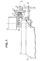
- This device comprises a rotary step-by-step motor 4, a thermal printing head 1 intended for printing a sheet of electro-sensitive paper 2, a roller 3 on which the sheet of paper 2 is placed, and transmission elements transforming the rotary movement printed by the motor 4, on the one hand in a rectilinear reciprocating movement animating the printing head 1, and on the other hand in a rotary movement animating the roller 3.
- the direction of the rectilinear reciprocating movement printed at the head d 'impression 1 is y'y. This direction is parallel to the registration lines of the sheet 2 and the axis of rotation of the roller 3.
- a rotation of the roller 3 causes a displacement of the sheet of paper in a direction perpendicular to the writing lines.
- the principle implemented by the transmission elements of the device consists in synchronizing the movements of the print head 1 and of the roller 3 in order to allow a paper advance at the end of the writing of a line and before the start. the registration of a new line.
- the displacement of the print head 1 is generated by an eccentric 5 placed inside a light formed in the print head 1.
- this eccentric 5 is coupled to the motor 4 by means of a transmission axis 6 which corresponds to the axis of rotation of the eccentric 5 and to the motor shaft 4. It follows that the eccentric 5 transforms the stepping rotation movement generated by the motor 4 into a reciprocating rectilinear movement, of direction y'y, animating the print head 1.
- the displacement of the print head 1 is carried out from a first extreme position (position 1) to a second extreme position (position 2) .
- the pitch of the motor 4 is 90 ° and the number of stops of this motor during a cycle of the translational movement of the print head 1 is four. Each engine stop corresponds to an extreme position of the print head 1.
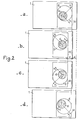
- FIGS. 2a, 2b, 2c and 2d allow a better understanding of the movement animating the print head 1.
- the print head 1 the transmission axis 6, the eccentric 5, and the rectangular section 30 of the light formed in the printing head 1, seen from the section plane AA of FIG. 1.
- an orthogonal coordinate system OX 1 y has also been shown, the origin of which O corresponds to the center of the section of the transmission axis 6. This coordinate system is only used to reveal the rotary movement of the eccentric 5.
- the instants t l , t 2 , t 3 and t 4 correspond to the four instants at which the engine 4 stops during a cycle of the translational movement of the print head 1.
- Figure 2a corresponds to the position of the print head 1 at time t l .
- This position is the first extreme position of the print head 1, it is position 1.
- the axis of transmission 6 rotates 90 ° and causes a linear displacement of the print head 1. This displacement has the amplitude d.
- the eccentric 5 and the print head 1 are in the position shown in Figure 2b.
- This position corresponds to the second extreme position of the print head 1, this is position 2.
- the transmission axis 6 again rotates 90 °, but this rotation does not cause no translation of the print head 1.
- the print head 1 is therefore always in position 2 as shown in FIG. 2c.
- the electrodes of the print head 1 are controlled to print the sheet at the characteristic instants t l , t 2 , t 3 and t 4 of each cycle of the movement of the print head 1. In fact, these instants correspond to on the one hand at the instants of stopping the printhead 1 and on the other hand at extreme positions of the printhead 1. For each writing line, it is necessary that each electrode can print two different dots.
- the method consists in giving a first print order to the n electrodes at time t l , in moving the print head 1 between the instants t 1 and t 2 , in giving a second print order to the n electrodes at at time t 2 , to command an advance of the printing sheet between times t 2 and t 3 so as to present to the n electrodes a blank writing line, and so on.
- transmission elements have been placed between the motor 4 and the roller 3 which transforms the rotary movement of the motor 4 into a rotary movement which only drives the roller 3 'between, on the one hand the instants t 2 and t 31 and on the other hand the instants t 3 and t 4 of the rotation cycle of the motor 4.
- the advance of the sheet will be controlled between the end of the inscription of each line and the start of the registration of the next line.
- the motor 4 is coupled to the roller 3 via a transmission consisting of: a first synchronous pulley 7 whose axis of rotation corresponds to l axis 6, and a second synchronous pulley 9 linked to the synchronous pulley 7 by means of the toothed belt 8, a worm 11 whose axis of rotation 10 of direction x'x corresponds to l the axis of rotation of the pulley 9, of a toothed wheel 12 meshed with the worm 11, of a toothed wheel 13 whose axis of rotation 20 corresponds to the axis of rotation of the toothed wheel 12, and of a toothed wheel 14 meshed with the toothed wheel 13 and having an axis of rotation 15 corresponding to the axis of rotation of the roller 3.
- a transmission consisting of: a first synchronous pulley 7 whose axis of rotation corresponds to l axis 6, and a second synchronous pulley 9 linked to the synchronous pulley 7 by means of the toothed belt
- the transmission consisting of pulleys 7 and 9, the transmission axis 6, the axis of rotation 10, and the toothed belt 8, serves to drive the worm 11 in a rotational movement around the axis 10.
- the multiplication ratio of this gear is 1, so that a 90 ° rotation of the motor shaft 4 corresponds to a 90 ° rotation of the screw 11.
- the gear consisting of the toothed wheels 13 and 14 and transmission axes 15 and 20 it serves to drive the roller 3 in a rotational movement around the axis 15.
- Each gear step of the tooth wheel 12 corresponds to a rotation of the roller 3 which drives an advance of sheet 2 over a length equal to the interval between two consecutive inscription lines.
- the gear relating to the toothed wheel 12 and the worm 11 is the most complex. To better understand its operation, this gear has been represented in FIG. 3, seen from the section plane BB of FIG. 1.
- the face of the tooth wheel 12 which is seen from this cutting plane BB comprises all of the teeth d. (i varying from 1 to 32). These teeth i have a cylindrical shape. They are distributed on a concentric circle at the circumference of the wheel and mesh successively in the thread of the endless screw 11.
- the shape of the thread is alternately helical and circular.
- the rhythm of the change in shape of the thread corresponds to a quadrant of the screw 11. In fact, as shown in FIG. 3, the thread of the screw 11 is circular on a quadrant of the screw, helical on the next quadrant, then circular And so on.
- the screw comprises an active part, consisting of the two quadrants comprising the thread of helical shape, and an inactive part consisting of the two quadrants comprising the thread of circular shape.
- an active part consisting of the two quadrants comprising the thread of helical shape
- an inactive part consisting of the two quadrants comprising the thread of circular shape.
- the screw 11 is previously positioned so that the active part of the screw corresponds to a pitch of rotation of the motor 4 taking place, either between the instants t 2 and t 3 , or between the instants t 4 and t l of each cycle of rotation, and that the inactive part corresponds to the pitch of rotation taking place either between the instants t 1 and t 2 , or between the instants t 3 and t 4 .
- the screw 11 generates a rotation of the toothed wheel 12 and therefore an advance of the sheet 2, only between the instants t 2 and t 3 and that between the instants t 4 and t of each rotation cycle motor 4.
- the roll 3 can easily be moved away from the print head 1.
- the toothed wheels 13 and 14 constitute a convenient means for transmitting a rotational movement to the roller 3 while allowing it to be moved away from the print head 1.
Landscapes
- Character Spaces And Line Spaces In Printers (AREA)
- Impact Printers (AREA)
- Common Mechanisms (AREA)
Abstract
La présente invention concerne les dispositifs électro-mécaniques d'impression pour imprimantes du type série-parallèle. Le dispositif comporte une tête d'impression (1) destinée à imprimer une feuille (3), un moteur rotatif (4), et des éléments de transmission transformant le mouvement rotatif généré par le moteur (4), d'une part en un mouvement alternatif rectiligne animant la tête d'impression (1), et d'autre part en un mouvement animant la feuille d'impression (2) en synchronisme avec le mouvement alternatif de la tête d'impression (1). Application aux télécopieurs.The present invention relates to electro-mechanical printing devices for printers of the series-parallel type. The device comprises a print head (1) intended for printing a sheet (3), a rotary motor (4), and transmission elements transforming the rotary movement generated by the motor (4), on the one hand into a reciprocating rectilinear movement animating the printing head (1), and on the other hand in a movement animating the printing sheet (2) in synchronism with the reciprocating movement of the printing head (1). Application to fax machines.
Description
La présente invention concerne les dispositifs électromécaniques d'impression pour imprimantes du type série-parallèle.The present invention relates to electromechanical printing devices for printers of the series-parallel type.
Les imprimantes de type série-parallèle sont bien connues. Leur tête d'impression est animée d'un mouvement rectiligne alternatif parallèle aux lignes d'inscription et comporte n éléments (n entier positif) pouvant imprimer chacun une suite de k points consécutifs sur une ligne (k entier positif). Pour assurer le déplacement de la tête d'impression, les imprimantes actuelles utilisent un moteur rotatif couplé à un excentrique (ou à une came) placé dans une lumière ménagée dans la tête d'impression. En outre, ces imprimantes comportent un moteur rotatif auxiliaire couplé à un dispositif de déplacement de. la feuille d'impression, et un circuit de commande des moteurs. Ce circuit commande les moteurs afin d'animer la tête d'impression d'un mouvement linéaire alternatif parallèle aux lignes d'inscription et d'avancer la feuille d'impression dès que l'inscription d'une ligne est terminée. Les deux moteurs et leur circuit de commande ont pour inconvénient d'être coûteux.Serial-parallel type printers are well known. Their print head is driven in an alternating rectilinear movement parallel to the writing lines and comprises n elements (n positive integer) each capable of printing a series of k consecutive dots on a line (k positive integer). To ensure the displacement of the print head, current printers use a rotary motor coupled to an eccentric (or to a cam) placed in a light formed in the print head. In addition, these printers include an auxiliary rotary motor coupled to a movement device. the printing sheet, and a motor control circuit. This circuit controls the motors in order to animate the print head in a reciprocating linear movement parallel to the writing lines and to advance the printing sheet as soon as the writing of a line is finished. The disadvantage of the two motors and their control circuit is that they are expensive.
Par ailleurs il est connu un dispositif d'impression comportant un seul moteur, un rouleau supportant une feuille, une tête d'impression fixe, des premiers éléments de transmission transformant le mouvement rotatif généré par le moteur en un mouvement de rotation du rouleau autour de son axe, pour faire avancer la feuille, et des seconds éléments de transmission transformant le mouvement rotatif généré par le moteur en un mouvement alternatif et rectiligne déplaçant le rouleau parallèlement à son axe et en synchronisme avec son mouvement de rotation. Un tel dispositif est décrit dans la demande de brevet européen n° 80 400632.8, il a pour inconvénient un accès difficile à la feuille de papier, la tête d'impression étant fixée au chassis, d'une part, et d'autre part le rouleau étant relié au chassis par deux systèmes de transmission mécanique, l'un pour assurer son déplacement alternatif et rectiligne et l'autre pour assurer sa rotation.Furthermore, a printing device is known comprising a single motor, a roller supporting a sheet, a fixed printing head, first transmission elements transforming the rotary movement generated by the motor into a rotation movement of the roller around its axis, to advance the sheet, and second transmission elements transforming the rotary movement generated by the motor into a reciprocating and rectilinear movement moving the roller parallel to its axis and in synchronism with its rotational movement. Such a device is described in European patent application No. 80 400632.8, it has the disadvantage of difficult access to the sheet of paper, the print head being fixed to the frame, on the one hand, and on the other hand the roller being connected to the chassis by two mechanical transmission systems, one to ensure its alternating and rectilinear movement and the other to ensure its rotation.
La présente invention a pour objet un dispositif électromécanique d'impression ayant pour avantage de n'utiliser qu'un seul moteur rotatif pour commander à la fois l'avance du papier et le déplacement de la tête d'impression, ce qui entraîne un coût de réalisation moins élevé, et d'autre part nécessitant seulement une rotation du rouleau, ce qui permet de simplifier le système le mettant en mouvement afin de pouvoir déplacer facilement le rouleau pour manipuler la feuille de papier.The present invention relates to an electromechanical printing device having the advantage of using only one rotary motor for control both the advance of the paper and the movement of the print head, which results in a lower production cost, and on the other hand requiring only a rotation of the roller, which simplifies the system putting it in motion so that you can easily move the roller to handle the sheet of paper.
Selon l'invention, un dispositif électromécanique d'impression pour imprimante du type série-parallèle, comportant : une tête d'impression destinée à imprimer une feuille ; un moteur rotatif ; un rouleau supportant la feuille ; des premiers éléments de transmission transformant le mouvement rotatif généré par le moteur en un mouvement de rotation du rouleau autour de son axe, pour faire avancer la feuille, est caractérisé en ce qu'il comporte des seconds éléments de transmission transformant le mouvement rotatif généré par le moteur en un mouvement alternatif et rectiligne appliqué à la tête d'impression, perpendiculaire et synchrone avec le mouvement d'avancement de la feuille.According to the invention, an electromechanical printing device for a printer of the series-parallel type, comprising: a printing head intended for printing a sheet; a rotary motor; a roller supporting the sheet; first transmission elements transforming the rotary movement generated by the motor into a rotation movement of the roller around its axis, to advance the sheet, is characterized in that it comprises second transmission elements transforming the rotary movement generated by the motor in an alternating and rectilinear movement applied to the print head, perpendicular and synchronous with the movement of advancement of the sheet.
L'invention sera mieux comprise et d'autres caractéristiques apparaîtront à l'aide de la description et des dessins s'y rapportant sur lesquels :
- la figure 1 est un exemple d'un mode de réalisation du dispositif selon l'invention ;
- les figures 2 et 3 représentent des éléments du dispositif vus selon des plans de coupe de la figure 1.
- La figure 1 représente un mode de réalisation du dispositif selon l'invention pour une imprimante thermique du type série-parallèle dont la tête d'impression a la largeur d'une ligne et est munie de n électrodes (non représentées); chaque électrode pouvant imprimer deux points par un déplacement de la tête d'impression d'une distance égale à la moitié de l'intervalle séparant deux électrodes consécutives.
- Figure 1 is an example of an embodiment of the device according to the invention;
- FIGS. 2 and 3 represent elements of the device seen according to the section planes of FIG. 1.
- FIG. 1 represents an embodiment of the device according to the invention for a thermal printer of the series-parallel type, the print head of which is the width of a line and is provided with n electrodes (not shown); each electrode being able to print two points by a displacement of the print head by a distance equal to half the interval separating two consecutive electrodes.
Ce dispositif comporte un moteur rotatif pas à pas 4, une tête d'impression thermique 1 destinée à imprimer une feuille de papier électro- sensible 2, un rouleau 3 sur lequel est placé la feuille de papier 2, et des éléments de transmission transformant le mouvement rotatif imprimé par le moteur 4, d'une part en un mouvement alternatif rectiligne animant la tête d'impression 1, et d'autre part en un mouvement rotatif animant le rouleau 3. La direction du mouvement alternatif rectiligne imprimé à la tête d'impression 1 est y'y. Cette direction est parallèle aux lignes d'inscription de la feuille 2 et à l'axe de rotation du rouleau 3. Il en résulte qu'une rotation du rouleau 3 entraîne un déplacement de la feuille de papier dans une direction perpendiculaire aux lignes d'inscription.This device comprises a rotary step-by-step motor 4, a
Le principe mis en oeuvre par les éléments de transmission du dispositif consiste à synchroniser les mouvements de la tête d'impression 1 et du rouleau 3 afin de permettre une avance du papier à la fin de l'inscription d'une ligne et avant le début de l'inscription d'une nouvelle ligne.The principle implemented by the transmission elements of the device consists in synchronizing the movements of the
Le déplacement de la tête d'impression 1 est engendré par un excentrique 5 placé à l'intérieur d'une lumière ménagée dans la tête d'impression 1. En effet, cet excentrique 5 est couplé au moteur 4 par l'intermédiaire d'un axe de transmission 6 qui correspond à l'axe de rotation de l'excentrique 5 et à l'arbre du moteur 4. Il s'ensuit que l'excentrique 5 transforme le mouvement de rotation pas à pas engendré par le moteur 4 en un mouvement rectiligne alternatif, de direction y'y, animant la tête d'impression 1. Le déplacement de la tête d'impression 1 s'effectue d'une première position extrême (position 1) à une seconde position extrême (position 2). Le pas du moteur 4 est de 90° et le nombre d'arrêts de ce moteur pendant un cycle du mouvement de translation de la tête d'impression 1 est quatre. Chaque arrêt du moteur correspond à une position extrême de la tête d'impression 1.The displacement of the
Les figures 2a, 2b, 2c et 2d permettent de mieux comprendre le mouvement animant la tête d'impression 1. Sur ces figures, sont représentés la tête d'impression 1, l'axe de transmission 6, l'excentrique 5, et la section rectangulaire 30 de la lumière ménagée dans la tête d'impression 1, vus du plan de coupe AA de la figure 1.FIGS. 2a, 2b, 2c and 2d allow a better understanding of the movement animating the
Sur ces figures, il a aussi été représenté un repère orthogonal OX 1y dont l'origine O correspond au centre de la section de l'axe de transmission 6. Ce repère n'est utilisé que pour faire apparaître le mouvement rotatif de l'excentrique 5. Les instants tl, t2, t3 et t4 correspondent aux quatre instants auxquels ont lieu l'arrêt du moteur 4 pendant un cycle du mouvement de translation de la tête d'impression 1.In these figures, an orthogonal coordinate system OX 1 y has also been shown, the origin of which O corresponds to the center of the section of the
La figure 2a correspond à la position de la tête d'impression 1 à l'instant tl. Cette position est la première position extrême de la tête d'impression 1, c'est la position 1. Entre les instants t et t2, l'axe de transmission 6 tourne de 90° et entraîne un déplacement linéaire de la tête d'impression 1. Ce déplacement a pour amplitude d . A l'instant t2, l'excentrique 5 et la tête d'impression 1 sont dans la position représentée sur la figure 2b. Cette position correspond à la seconde position extrême de la tête d'impression 1, c'est la position 2. Entre les instants t2 et t3, l'axe de transmission 6 tourne de nouveau de 90°, mais cette rotation ne provoque pas de translation de la tête d'impression 1. A l'instant t3, la tête d'impression 1 est donc toujours dans la position 2 comme représenté sur la figure 2c. Entre les instants t3 et t4, l'axe de transmission 6 tourne encore de 90°. Cette fois-ci, la tête d'impression 1 est déplacée de la position 2 à la position 1. A l'instant t4, la tête d'impression 1 est donc dans la position 1 comme représentée sur la figure 2d. Enfin, entre l'instant t4 et l'instant t du cycle suivant, a lieu une nouvelle rotation de 90° de l'axe de transmission 6. A l'instant t1 du cycle suivant, la position de la tête d'impression 1 est alors de nouveau celle montrée sur la figure 2a, c'est-à-dire la position 1. Le mouvement cyclique se poursuit ensuite comme il a été décrit.Figure 2a corresponds to the position of the
Les électrodes de la tête d'impression 1 sont commandées pour imprimer la feuille aux instants caractéristiques tl, t2, t3 et t4 de chaque cycle du mouvement de la tête d'impression 1. En effet, ces instants correspondent d'une part aux instants d'arrêt de la tête d'impression 1 et d'autre part à des positions extrêmes de la tête d'impression 1. Pour chaque ligne d'inscription, il est nécessaire que chaque électrode puisse imprimer deux points différents. La méthode consiste à donner un premier ordre d'impression aux n électrodes à l'instant tl, à déplacer la tête d'impression 1 entre les instants t1 et t2, à donner un deuxième ordre d'impression aux n électrodes à l'instant t2, à commander une avance de la feuille d'impression entre les instants t2 et t3 de façon à présenter aux n électrodes une ligne d'inscription vierge, et ainsi de suite. Pour mettre en oeuvre cette méthode à l'aide du seul moteur 4, il a été placé entre le moteur 4 et le rouleau 3 des éléments de transmission qui transforme le mouvement rotatif du moteur 4 en un mouvement rotatif n'animant le rouleau 3 qu'entre, d'une part les instants t2 et t31 et d'autre part les instants t3 et t4 du cycle de rotation du moteur 4. Ainsi l'avance de la feuille sera commandée entre la fin de l'inscription de chaque ligne et le début de l'inscription de la ligne suivante.The electrodes of the
Les éléments de transmission qui permettent de mettre en oeuvre cette méthode sont représentés sur la figure 1. Sur cette figure, il apparaît que le moteur 4 est couplé au rouleau 3 par l'intermédiaire d'une transmission constituée : d'une première poulie synchrone 7 dont l'axe de rotation correspond à l'axe 6, et d'une deuxième poulie synchrone 9 liée à la poulie synchrone 7 par l'intermédiaire de la courroie crantée 8, d'une vis sans fin 11 dont l'axe de rotation 10 de direction x'x correspond à l'axe de rotation de la poulie 9, d'une roue à dents 12 engrenée à la vis sans fin 11, d'une roue dentée 13 dont l'axe de rotation 20 correspond à l'axe de rotation de la roue dentée 12, et d'une roue dentée 14 engrenée à la roue dentée 13 et ayant un axe de rotation 15 correspondant à l'axe de rotation du rouleau 3.The transmission elements which make it possible to implement this method are shown in Figure 1. In this figure, it appears that the motor 4 is coupled to the roller 3 via a transmission consisting of: a first synchronous pulley 7 whose axis of rotation corresponds to
la transmission constituée des poulies 7 et 9, de l'axe de transmission 6,de l'axe de rotation 10, et de la courroie crantée 8, sert à entraîner la vis sans fin 11 dans un mouvement de rotation autour de l'axe 10. Le rapport de multiplication de cet engrenage est 1, si bien qu'à une rotation de 90° de l'arbre du moteur 4 correspond une rotation de 90° de la vis 11. Quant à l'engrenage constitué des roues dentées 13 et 14 et des axes de transmission 15 et 20, il sert à entraîner le rouleau 3 dans un mouvement de rotation autour de l'axe 15. A chaque pas d'engrenage de la roue à dents 12 correspond une rotation du rouleau 3 qui entraîne une avance de la feuille 2 sur une longueur égale à l'intervalle entre deux lignes d'inscription consécutives.the transmission consisting of pulleys 7 and 9, the
L'engrenage relatif à la roue à dents 12 et à la vis sans fin 11 est le plus complexe. Pour mieux comprendre son fonctionnement cet engrenage a été représenté sur la figure 3, vu du plan de coupe BB de la figure 1.The gear relating to the
La face de la roue à dents 12 qui est vue de ce plan de coupe BB comporte la totalité des dents d. (i variant de 1 à 32). Ces dents di ont une forme cylindrique. Elles sont réparties sur un cercle concentrique à la circonférence de la roue et s'engrènent successivement dans le filet de la vis sans fin 11. La forme du filet est alternativement hélicoïdal et circulaire. Le rythme du changement de forme du filet correspond à un quadrant de la vis 11. En effet, comme représenté sur la figure 3, le filet de la vis 11 est circulaire sur un quadrant de la vis, hélicoïdal sur le quadrant suivant, puis circulaire et ainsi de suite. Il peut donc être considéré que la vis comprend une partie active, constituée des deux quadrants comportant le filet de forme hélicoïdale, et une partie inactive constituée des deux quadrants comportant le filet de forme circulaire.Aux pas successifs de rotation de la vis 11 correspondent alternativement un quadrant comportant le filet de forme circulaire et un quadrant comportant le filet de forme hélicoïdale. La vis 11 est préalablement positionnée de façon que la partie active de la vis corresponde à un pas de rotation du moteur 4 ayant lieu, soit entre les instants t2 et t3, soit entre les instants t4 et tl de chaque cycle de rotation, et que la partie inactive corresponde au pas de rotation ayant lieu soit entre les instants t1 et t2, soit entre les instants t3 et t4.The face of the
Ainsi, la vis 11 n'engendre une rotation de la roue à dents 12 et donc une avance de la feuille 2, qu'entre les instants t2 et t3 et qu'entre les instants t4 et t de chaque cycle de rotation du moteur 4.Thus, the
Le fonctionnement du dispositif d'impression selon l'invention pendant un cycle de rotation du moteur 4 se résume de la façon suivante :The operation of the printing device according to the invention during a rotation cycle of the motor 4 can be summarized as follows:
Instant tl : la tête d'impression 1 est dans la position 1; les n électrodes sont commandées pour imprimer au plus n points sur une ligne x de la feuille 3.Instant t l : the
Entre les instants t1 et t2 : la tête d'impression 1 est déplacée de la position 1 à la position 2. La feuille 3 n'est pas déplacée.Between times t 1 and t 2 : the
Instant t2 : la tête d'impression 1 est dans la position 2; les n électrodes sont commandées pour imprimer au plus n points sur la ligne x de la feuille 3.Instant t 2 : the
Entre les instants t2 et t3 : la feuille de papier 3 est avancée. La tête d'impression 1 reste dans la position 2.Between times t 2 and t 3 : the sheet of paper 3 is advanced. The
Instant t3 : la tête d'impression 1 est dans la position 2; les n électrodes sont commandées pour imprimer au plus n points sur la ligne Z suivant la ligne x.Instant t 3 : the
Entre les instants t3 et t4 : La tête d'impression 1 est déplacée de la position 2 à la position 1. La feuille de papier 3 n'est pas avancée.Between times t3 and t 4 : The
Instant t4 :la tête d'impression 1 est dans la position 1; les n électrodes sont commandées pour une nouvelle impression de la ligne z.Instant t 4 : the
Entre l'instant t4 et l'instant t1d'un nouveau cycle de rotation : la tête d'impression 1 reste dans la position 1. La feuille 3 est avancée.Puis le cycle du mouvement reprend.Between time t 4 and time t 1 of a new rotation cycle: the
Pour manipuler la feuille de papier 2, par exemple quand on installe un nouveau rouleau de papier, le rouleau 3 peut facilement être écarté de la tête d'impression 1. Les roues dentées 13 et 14 constituent un moyen commode pour transmettre un mouvement de rotation au rouleau 3 tout en permettant de l'écarter de la tête d'impression 1.To handle the sheet of paper 2, for example when installing a new paper roll, the roll 3 can easily be moved away from the
Il est à la portée de l'homme de l'art d'utiliser d'autres éléments pour réaliser cette transmission d'un mouvement de rotation synchrone, notamment d'utiliser deux poulies synchrones reliées par une courroie crantée.It is within the reach of those skilled in the art to use other elements to achieve this transmission of a synchronous rotational movement, in particular to use two synchronous pulleys connected by a toothed belt.
L'invention n'est pas limitée aux modes de réalisation décrits et représentés. En particulier, il est à la portée de l'homme de l'art de réaliser des engrenages autres que ceux décrits sans sortir du cadre de l'invention.The invention is not limited to the embodiments described and shown. In particular, it is within the reach of those skilled in the art to produce gears other than those described without departing from the scope of the invention.
Claims (3)
Applications Claiming Priority (2)
| Application Number | Priority Date | Filing Date | Title |
|---|---|---|---|
| FR8101464A FR2498524B1 (en) | 1981-01-27 | 1981-01-27 | ELECTROMECHANICAL PRINTING DEVICE FOR SERIAL-PARALLEL PRINTER AND FAX MACHINE COMPRISING SUCH A DEVICE |
| FR8101464 | 1981-01-27 |
Publications (3)
| Publication Number | Publication Date |
|---|---|
| EP0057118A2 true EP0057118A2 (en) | 1982-08-04 |
| EP0057118A3 EP0057118A3 (en) | 1982-08-18 |
| EP0057118B1 EP0057118B1 (en) | 1985-01-23 |
Family
ID=9254546
Family Applications (1)
| Application Number | Title | Priority Date | Filing Date |
|---|---|---|---|
| EP82400032A Expired EP0057118B1 (en) | 1981-01-27 | 1982-01-08 | Electromechanical printing mechanism for a serial parallel printer |
Country Status (5)
| Country | Link |
|---|---|
| US (1) | US4420763A (en) |
| EP (1) | EP0057118B1 (en) |
| JP (1) | JPS57144781A (en) |
| DE (1) | DE3261980D1 (en) |
| FR (1) | FR2498524B1 (en) |
Cited By (7)
| Publication number | Priority date | Publication date | Assignee | Title |
|---|---|---|---|---|
| GB2140746A (en) * | 1983-05-31 | 1984-12-05 | Alps Electric Co Ltd | Thermal printer |
| EP0143522A1 (en) * | 1983-09-29 | 1985-06-05 | Ing. C. Olivetti & C., S.p.A. | Line spacing mechanism for printing machine |
| EP0158017A2 (en) * | 1984-01-31 | 1985-10-16 | Nec Home Electronics Ltd. | Dot line printer |
| EP0387698A2 (en) * | 1989-03-13 | 1990-09-19 | LEPTONS ITALIA S.p.A. | Thermal printer particularly for labels |
| EP0650845A2 (en) * | 1993-10-29 | 1995-05-03 | Hewlett-Packard Company | Media feed and carriage motion mechanism for shuttle-type printers |
| AP619A (en) * | 1994-08-24 | 1997-10-10 | Hyal Pharma Corp | Use of hyaluronic acid or salt for the treatment of a human having a stroke or myocardial infarction. |
| CN1065819C (en) * | 1995-02-03 | 2001-05-16 | 阿尔卑斯电气株式会社 | Heat-sensitive printer |
Families Citing this family (4)
| Publication number | Priority date | Publication date | Assignee | Title |
|---|---|---|---|---|
| US4520371A (en) * | 1982-12-30 | 1985-05-28 | International Business Machines Corporation | Multi-zone thermal print head |
| JPS6015170A (en) * | 1983-07-08 | 1985-01-25 | Hitachi Koki Co Ltd | Shuttle mechanism |
| US5106216A (en) * | 1989-11-22 | 1992-04-21 | Samsung Electronics Co., Ltd. | Device for driving a platen and carriage of a printing machine |
| JP3334185B2 (en) * | 1991-10-14 | 2002-10-15 | セイコーエプソン株式会社 | Printer |
Citations (3)
| Publication number | Priority date | Publication date | Assignee | Title |
|---|---|---|---|---|
| GB2015433A (en) * | 1978-02-27 | 1979-09-12 | Matsushita Electric Ind Co Ltd | Printer |
| GB2046177A (en) * | 1979-03-26 | 1980-11-12 | Seiko Instr & Electronics | Printer |
| EP0020212A1 (en) * | 1979-05-31 | 1980-12-10 | Enertec Societe Anonyme | Printer having a mechanism for transversal movement of a platen-supported recording material relative to a printhead |
Family Cites Families (4)
| Publication number | Priority date | Publication date | Assignee | Title |
|---|---|---|---|---|
| IT1000641B (en) * | 1973-12-28 | 1976-04-10 | Olivetti & Co Spa | PERFECTED ELECTROTHERMIC PRINTING UNIT |
| FR2300678A1 (en) * | 1975-02-13 | 1976-09-10 | Logabax | PRINTING DEVICE FOR FAST PRINTERS |
| JPS5829761B2 (en) * | 1975-08-13 | 1983-06-24 | 住友化学工業株式会社 | Hydrous insecticidal composition |
| IT1108649B (en) * | 1978-04-14 | 1985-12-09 | Olivetti C Ing E C Spa | POINT PRINTING DEVICE |
-
1981
- 1981-01-27 FR FR8101464A patent/FR2498524B1/en not_active Expired
-
1982
- 1982-01-08 EP EP82400032A patent/EP0057118B1/en not_active Expired
- 1982-01-08 DE DE8282400032T patent/DE3261980D1/en not_active Expired
- 1982-01-18 US US06/340,018 patent/US4420763A/en not_active Expired - Fee Related
- 1982-01-25 JP JP57009033A patent/JPS57144781A/en active Pending
Patent Citations (3)
| Publication number | Priority date | Publication date | Assignee | Title |
|---|---|---|---|---|
| GB2015433A (en) * | 1978-02-27 | 1979-09-12 | Matsushita Electric Ind Co Ltd | Printer |
| GB2046177A (en) * | 1979-03-26 | 1980-11-12 | Seiko Instr & Electronics | Printer |
| EP0020212A1 (en) * | 1979-05-31 | 1980-12-10 | Enertec Societe Anonyme | Printer having a mechanism for transversal movement of a platen-supported recording material relative to a printhead |
Cited By (10)
| Publication number | Priority date | Publication date | Assignee | Title |
|---|---|---|---|---|
| GB2140746A (en) * | 1983-05-31 | 1984-12-05 | Alps Electric Co Ltd | Thermal printer |
| EP0143522A1 (en) * | 1983-09-29 | 1985-06-05 | Ing. C. Olivetti & C., S.p.A. | Line spacing mechanism for printing machine |
| EP0158017A2 (en) * | 1984-01-31 | 1985-10-16 | Nec Home Electronics Ltd. | Dot line printer |
| EP0158017A3 (en) * | 1984-01-31 | 1986-01-29 | Nec Home Electronics Ltd. | Dot line printer |
| EP0387698A2 (en) * | 1989-03-13 | 1990-09-19 | LEPTONS ITALIA S.p.A. | Thermal printer particularly for labels |
| EP0387698A3 (en) * | 1989-03-13 | 1991-07-10 | LEPTONS ITALIA S.p.A. | Thermal printer particularly for labels |
| EP0650845A2 (en) * | 1993-10-29 | 1995-05-03 | Hewlett-Packard Company | Media feed and carriage motion mechanism for shuttle-type printers |
| EP0650845A3 (en) * | 1993-10-29 | 1997-02-19 | Hewlett Packard Co | Media feed and carriage motion mechanism for shuttle-type printers. |
| AP619A (en) * | 1994-08-24 | 1997-10-10 | Hyal Pharma Corp | Use of hyaluronic acid or salt for the treatment of a human having a stroke or myocardial infarction. |
| CN1065819C (en) * | 1995-02-03 | 2001-05-16 | 阿尔卑斯电气株式会社 | Heat-sensitive printer |
Also Published As
| Publication number | Publication date |
|---|---|
| US4420763A (en) | 1983-12-13 |
| JPS57144781A (en) | 1982-09-07 |
| FR2498524A1 (en) | 1982-07-30 |
| EP0057118A3 (en) | 1982-08-18 |
| DE3261980D1 (en) | 1985-03-07 |
| FR2498524B1 (en) | 1986-07-25 |
| EP0057118B1 (en) | 1985-01-23 |
Similar Documents
| Publication | Publication Date | Title |
|---|---|---|
| EP0057118B1 (en) | Electromechanical printing mechanism for a serial parallel printer | |
| FR2565526A1 (en) | PRINTING APPARATUS AND CUTTING MECHANISM | |
| WO2010063353A1 (en) | Device for supplying power to a conversion unit with a continuous strip substrate for a power supply station in a packaging production machine | |
| FR2636149A1 (en) | Transmission device with intermittent rotational movement for an electrical apparatus remote control mechanism | |
| FR2472973A1 (en) | ELECTRONIC WRITING MACHINE | |
| EP0020991B1 (en) | Optically functioning encoder unit for controlling a bidirectional movement and its use in controlling stepping motors | |
| JP3151328B2 (en) | Recovery device for inkjet printer | |
| EP0020212B1 (en) | Printer having a mechanism for transversal movement of a platen-supported recording material relative to a printhead | |
| JPS58191182A (en) | Apparatus for feeding ink ribbon | |
| FR2490150A1 (en) | INTERLINE MECHANISM FOR WRITING MACHINES AND SIMILAR MACHINES | |
| EP1494872B1 (en) | Paper feeding device for dot printers for example ink jet photographic printers | |
| EP0077240B1 (en) | Printed tape inductance and transmitter using such an inductance | |
| FR2601744A1 (en) | INTERMITTENT GEAR MECHANISM | |
| EP4031828B1 (en) | Target launching device | |
| WO1998001245A1 (en) | Device for adjusting the size of a machine tool blank holder | |
| EP0112759A1 (en) | Mechanical multiplexing device for a thermal printer | |
| FR2486611A1 (en) | Rotary to reciprocation motion converter - has driving gears with teeth on only part of their circumference engaging driven output gear | |
| EP0604317B1 (en) | Device for setting the print wheels of a franking machine | |
| EP0085007B1 (en) | Numerically controlled machine for cutting glass plates | |
| EP1742802B1 (en) | Compact disc printing device | |
| JPH06289452A (en) | Sprocket wheel for feeding film and film feed device using it | |
| JP3811951B2 (en) | Thermal transfer printer | |
| FR2847512A1 (en) | Folding cylinder drive for rotating printing machine, is coupled to cylinder segments with position adjustment unit having set limit values for their reciprocal angular shift to limit possibility of reciprocal rotation, pinion | |
| EP0023452A1 (en) | Printing apparatus with pulverulent magnetic toner | |
| EP1251010A1 (en) | Office machine with printer and scanner and multi-functional motor |
Legal Events
| Date | Code | Title | Description |
|---|---|---|---|
| PUAI | Public reference made under article 153(3) epc to a published international application that has entered the european phase |
Free format text: ORIGINAL CODE: 0009012 |
|
| PUAL | Search report despatched |
Free format text: ORIGINAL CODE: 0009013 |
|
| AK | Designated contracting states |
Designated state(s): DE GB NL |
|
| AK | Designated contracting states |
Designated state(s): DE GB NL |
|
| 17P | Request for examination filed |
Effective date: 19830114 |
|
| GRAA | (expected) grant |
Free format text: ORIGINAL CODE: 0009210 |
|
| AK | Designated contracting states |
Designated state(s): DE GB NL |
|
| REF | Corresponds to: |
Ref document number: 3261980 Country of ref document: DE Date of ref document: 19850307 |
|
| PLBE | No opposition filed within time limit |
Free format text: ORIGINAL CODE: 0009261 |
|
| STAA | Information on the status of an ep patent application or granted ep patent |
Free format text: STATUS: NO OPPOSITION FILED WITHIN TIME LIMIT |
|
| 26N | No opposition filed | ||
| PGFP | Annual fee paid to national office [announced via postgrant information from national office to epo] |
Ref country code: NL Payment date: 19890131 Year of fee payment: 10 |
|
| PGFP | Annual fee paid to national office [announced via postgrant information from national office to epo] |
Ref country code: GB Payment date: 19891231 Year of fee payment: 9 |
|
| PGFP | Annual fee paid to national office [announced via postgrant information from national office to epo] |
Ref country code: DE Payment date: 19900222 Year of fee payment: 9 |
|
| PG25 | Lapsed in a contracting state [announced via postgrant information from national office to epo] |
Ref country code: GB Effective date: 19910108 |
|
| PG25 | Lapsed in a contracting state [announced via postgrant information from national office to epo] |
Ref country code: NL Effective date: 19910801 |
|
| GBPC | Gb: european patent ceased through non-payment of renewal fee | ||
| NLV4 | Nl: lapsed or anulled due to non-payment of the annual fee | ||
| PG25 | Lapsed in a contracting state [announced via postgrant information from national office to epo] |
Ref country code: DE Effective date: 19911001 |