EP0057091A2 - Wärmeaustauscher für Kühlvorrichtungen - Google Patents
Wärmeaustauscher für Kühlvorrichtungen Download PDFInfo
- Publication number
- EP0057091A2 EP0057091A2 EP82300316A EP82300316A EP0057091A2 EP 0057091 A2 EP0057091 A2 EP 0057091A2 EP 82300316 A EP82300316 A EP 82300316A EP 82300316 A EP82300316 A EP 82300316A EP 0057091 A2 EP0057091 A2 EP 0057091A2
- Authority
- EP
- European Patent Office
- Prior art keywords
- sheet
- perforations
- heat exchanger
- lines
- tubing
- Prior art date
- Legal status (The legal status is an assumption and is not a legal conclusion. Google has not performed a legal analysis and makes no representation as to the accuracy of the status listed.)
- Ceased
Links
Images

Classifications
-
- F—MECHANICAL ENGINEERING; LIGHTING; HEATING; WEAPONS; BLASTING
- F28—HEAT EXCHANGE IN GENERAL
- F28F—DETAILS OF HEAT-EXCHANGE AND HEAT-TRANSFER APPARATUS, OF GENERAL APPLICATION
- F28F1/00—Tubular elements; Assemblies of tubular elements
- F28F1/10—Tubular elements and assemblies thereof with means for increasing heat-transfer area, e.g. with fins, with projections, with recesses
- F28F1/12—Tubular elements and assemblies thereof with means for increasing heat-transfer area, e.g. with fins, with projections, with recesses the means being only outside the tubular element
- F28F1/14—Tubular elements and assemblies thereof with means for increasing heat-transfer area, e.g. with fins, with projections, with recesses the means being only outside the tubular element and extending longitudinally
- F28F1/22—Tubular elements and assemblies thereof with means for increasing heat-transfer area, e.g. with fins, with projections, with recesses the means being only outside the tubular element and extending longitudinally the means having portions engaging further tubular elements
-
- F—MECHANICAL ENGINEERING; LIGHTING; HEATING; WEAPONS; BLASTING
- F25—REFRIGERATION OR COOLING; COMBINED HEATING AND REFRIGERATION SYSTEMS; HEAT PUMP SYSTEMS; MANUFACTURE OR STORAGE OF ICE; LIQUEFACTION SOLIDIFICATION OF GASES
- F25B—REFRIGERATION MACHINES, PLANTS OR SYSTEMS; COMBINED HEATING AND REFRIGERATION SYSTEMS; HEAT PUMP SYSTEMS
- F25B39/00—Evaporators; Condensers
- F25B39/04—Condensers
Definitions
- This invention relates to a heat exchange panel unit primarily for use in conjunction with a condenser coil of a refrigeration system in order to assist in the loss of heat to ambient air.
- a heat exchanger comprising a "serpentine" arrangement for the condenser tubing which is joined by longitudinal parallel spaced rods spot welded to the tubing and serving as a support and heat dissipating means.
- Such an arrangement has limited contact points for heat conduction to the rods from the tubing and a limited area for heat dissipation.
- the arrangement does provide relatively unrestricted air through-flow however. This construction is heavy and involves a complex assembly routine. Arrangements using cooling fins connected with the tubing are also known, but such constructions cannot be made sufficiently flat for many installations and are expensive in materials and manufacture.
- this invention is primarily concerned with a condenser for a domestic refrigerator, it is nevertheless usable generally as a heat exchanger where a metal area is to be attached to a tubing to afford better cooling or possibly warming.
- a heat exchange unit primarily for a refrigerator, the unit comprising a perforated sheet of metal material to which a tubing element is attached, the tubing carrying a fluid medium from which heat is to be lost, characterised by a sheet material of metal which has been perforated by a roller forming a rotary punch between the pinch of which the sheet is fed, the sheet comprising a plurality of longitudinally extending lines of regular spaced perforations wherein the material of each perforation is displaced during punching and turned back to one side of the sheet and around the periphery of the punched aperture, the sheet further including un-perforated strips between areas of said longitudinal lines of perforations, the strips supporting the tubing.
- the sheet will preferably include a number of parallel spaced non-perforated strips each of which may include a series of regularly spaced protuberances formed by indentations, onto which a straight run of the heat exchange tube may be positioned and thereafter spot welded to provide a firm connection affording good heat exchange properties.
- the tube will preferably be in the form of a "serpentine" extending along and then back over the spaced strip portions on the sheet.
- the sheet material will preferably be perforated in the manner disclosed in British Patent specification 1,312,053, but the perforating rollers will include cutting teeth of larger dimensions which produce a slot of an elongated and somewhat triangular shape in plan.
- the perforations have a length to breadth ratio of between 1:1 and 6:1.
- the roller producing the perforations may include across the width a number of teeth which form a series of perforations followed by a plain tooth-free zone which may be arranged to produce indentations in the unperforated strip, this then being followed by a second series of teeth and so on.
- the perforations may be produced by the roller and a co-acting die between the pinch of which the sheet is fed to provide a continuous production method. By this means the perforated material is simply cut through and there is no wastage or loss of metal.
- the manner of cutting the slots forming the perforations forms a sheet having excellent heat exchange properties which allows free passage of air therethrough, and the shape offers good rigidity to bending in all directions.
- the invention also is to be construed as embodying a method of manufacturing a heat exchanger substantially as hereinbefore defined.
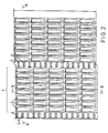
- FIG. 1 a part only of the heat exchange sheet is shown and this comprises a series of lines 1 formed by narrow elongate generally rectangular perforations or slots 2. Between each series of lines 1 a strip of non-perforated sheet material 3 is provided, with the strips being regularly spaced across the sheet width and extending parallel over the length of the sheet.
- Each of the strip portions 3 includes a number of evenly spaced upstanding protuberances, as viewed in Figure 1, formed by indentations 4 which serve as a support and basis for spot welding thereto tubing 5 forming a heat exchange duct or, in this instance, the serpentine of a refrigerator system.
- the coil is curved to turn through 180 and then extends along the next adjacent strip 3, this sinuous arrangement being present over the whole of the sheet.
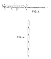
- the slots 2 have an elongated rectangular or possibly triangular-like shape with the cut through material being displaced and generally turned back to one side.
- the method of cutting may be as disclosed in Patent specification 1,312,053 as example.
- Figures 2, 3 and 4 show the sheet in reverse side view and sections illustrating the configuration of the slots.
- the material remaining as ribs between adjacent lines of perforations has a U-shape sectional profile caused by the displaced and turned-back material; the same is true for the cross-pieces between each perforation in a line.
- This profile affords good rigidity to bending of the sheet.
- the dimensions of the perforations may be adjusted acoording to requirements. For example, by making the length of each perforation smaller more cross-pieces are provided per unit length, giving better heat conduction from the strip 3, carrying the tubing, to the sheet between adjacent strips. However this also reduces the open area available for air-flow, thus effectively reducing heat loss to the air. In practice, therefore, a compromise by way of an optimum perforation dimension is provided according to a particular use.
- the pitch between the strips 3 is of the order of 5 to 6 centimetres and the pitch of the perforations (lengthwise) is two centimetres, whereas the pitch between adjacent slots forming the perforations is some 6 to 7 millimetres.
- each perforation defines a smooth sided aperture through which air may flow and circulate readily whilst paesing over a large area of metal to give good heat exchange and hence cooling.
- the pitch of the indentations 4 is of the order of 5 millimetres and is selected to provide 8 ufficient contact to obtain good heat exchange from the tubing spot welded thereto.
- This arrangement when applied to a heat ezchanger, offers considerable advantage as compared with a conventional refrigerator heat exchanger which uses a series of rods welded to the heat exchange serpentine.
- the surface area is much increased affording better heat dissipation and assembly, and manufacturing costs are significantly reduced as individual rods do not have to be placed in a jig and thereafter spot welded to the tube.
- a complete sheet of the perforated material in one piece may be placed over the whole serpentine and spot welded into place in a simple manner.
- the perforations in the sheet material may be produced by a method other than that herein disclosed and the perforations may be of differing shapes and sizes according to requirements.
- the embodiment disclosed shows the tubing 5 welded at intervals to the protrusions 4 but it is equally possible to simply spot weld the tube at spaced locations to the flat strip or to form the strip with a channel in which the tube is laid and then welded. It is important to provide good heat conduction between the tube and strip and where spot welding is used the spacing of the welds should be close enough to obtain good heat transference commensurate with economic production.
- Other arrangements comprise two staggered lines of protrusions between which the tube is positioned and welded thereto, or an arrangement where the strip has a deep channel in which the tube can be pressed so as to embrace a greater part of the tube thus providing good heat transfer.
- a second strip could be used to sandwich the tube the second strip being welded ot otherwise connected with the strip on the sheet. In general, welding is preferred for the tube to strip connection so as to provide continuity of metal for heat transference.
Landscapes
- Engineering & Computer Science (AREA)
- Physics & Mathematics (AREA)
- Mechanical Engineering (AREA)
- Thermal Sciences (AREA)
- General Engineering & Computer Science (AREA)
- Geometry (AREA)
- Bending Of Plates, Rods, And Pipes (AREA)
- Heat-Exchange Devices With Radiators And Conduit Assemblies (AREA)
Applications Claiming Priority (2)
| Application Number | Priority Date | Filing Date | Title |
|---|---|---|---|
| GB8102122 | 1981-01-23 | ||
| GB8102122 | 1981-01-23 |
Publications (2)
| Publication Number | Publication Date |
|---|---|
| EP0057091A2 true EP0057091A2 (de) | 1982-08-04 |
| EP0057091A3 EP0057091A3 (de) | 1982-10-27 |
Family
ID=10519175
Family Applications (1)
| Application Number | Title | Priority Date | Filing Date |
|---|---|---|---|
| EP82300316A Ceased EP0057091A3 (de) | 1981-01-23 | 1982-01-21 | Wärmeaustauscher für Kühlvorrichtungen |
Country Status (2)
| Country | Link |
|---|---|
| EP (1) | EP0057091A3 (de) |
| ES (1) | ES271039Y (de) |
Cited By (2)
| Publication number | Priority date | Publication date | Assignee | Title |
|---|---|---|---|---|
| WO1997029335A1 (en) * | 1996-02-08 | 1997-08-14 | Condenser Italiana S.R.L. | Heat exchanger for refrigeration devices, particularly for refrigerators for household use |
| WO2006067378A1 (en) * | 2004-12-22 | 2006-06-29 | Ti Group Automotive Systems Limited | A heat exchanger |
Families Citing this family (1)
| Publication number | Priority date | Publication date | Assignee | Title |
|---|---|---|---|---|
| WO2003031886A1 (es) * | 2001-10-05 | 2003-04-17 | Roman Gandara Granger | Condensador mejorado para sistema de refrigeracion |
Family Cites Families (10)
| Publication number | Priority date | Publication date | Assignee | Title |
|---|---|---|---|---|
| GB729671A (en) * | 1952-11-19 | 1955-05-11 | Standard Pressed Steel Co | Improvements in or relating to refrigerant condensers |
| FR1380673A (fr) * | 1963-10-22 | 1964-12-04 | Rubanox Soc | Perfectionnements aux échangeurs thermiques à convection |
| GB1006039A (en) * | 1964-03-26 | 1965-09-29 | Reiert Aluminium Metall | Improvements relating to heat exchangers |
| FR1396436A (fr) * | 1964-03-10 | 1965-04-23 | Rubanox Soc | Perfectionnements aux armoires frigorifiques |
| ES374251A1 (es) * | 1968-12-05 | 1971-12-16 | Chausson Usines Sa | Procedimiento para la fabricacion de aletas de regrigera- cion de radiadores y objetos analogos. |
| US3773455A (en) * | 1969-10-13 | 1973-11-20 | Flex O Glass Inc | Apparatus for forming plastic louver screen |
| GB1312053A (en) * | 1970-04-16 | 1973-04-04 | Bion Co Ltd Robert | Perforating strip material |
| US3665745A (en) * | 1970-05-04 | 1972-05-30 | Robert Bion And Co Ltd | Perforating apparatus and product |
| DE2027451A1 (de) * | 1970-06-04 | 1971-12-16 | Benteler Werke AG , 4800 Bielefeld | Wärmeaustauscher fur Heiz und Kühl gerate |
| DE2143886A1 (de) * | 1971-04-08 | 1972-10-19 | Contardo Gmbh | Verfahren zum Herstellen von Elementen für statische Kondensatoren und plattenförmiges Kondensatorelement |
-
1982
- 1982-01-21 EP EP82300316A patent/EP0057091A3/de not_active Ceased
- 1982-01-23 ES ES1982271039U patent/ES271039Y/es not_active Expired
Cited By (2)
| Publication number | Priority date | Publication date | Assignee | Title |
|---|---|---|---|---|
| WO1997029335A1 (en) * | 1996-02-08 | 1997-08-14 | Condenser Italiana S.R.L. | Heat exchanger for refrigeration devices, particularly for refrigerators for household use |
| WO2006067378A1 (en) * | 2004-12-22 | 2006-06-29 | Ti Group Automotive Systems Limited | A heat exchanger |
Also Published As
| Publication number | Publication date |
|---|---|
| ES271039U (es) | 1983-09-01 |
| EP0057091A3 (de) | 1982-10-27 |
| ES271039Y (es) | 1984-03-16 |
Similar Documents
| Publication | Publication Date | Title |
|---|---|---|
| US6286201B1 (en) | Apparatus for fin replacement in a heat exchanger tube | |
| US5353868A (en) | Integral tube and strip fin heat exchanger circuit | |
| CA1277976C (en) | Lanced sine-wave heat exchanger | |
| US5509469A (en) | Interrupted fin for heat exchanger | |
| US2347957A (en) | Heat exchange unit | |
| JP3292077B2 (ja) | 熱交換器及び空気調和機 | |
| US2195259A (en) | Condenser for mechanical refrigerators | |
| JP2004092942A (ja) | 熱交換器 | |
| JPS6238639B2 (de) | ||
| US4775007A (en) | Heat exchanger for an air-conditioning apparatus | |
| JP2002228379A (ja) | 熱交換器のルーバーフィンおよびその熱交換器並びにそのルーバーフィンの組付け方法 | |
| US3241610A (en) | Fin and tube stock assemblies for heat exchange units | |
| US3224503A (en) | Heat exchanger | |
| JPH10300375A (ja) | 熱交換器 | |
| EP0057091A2 (de) | Wärmeaustauscher für Kühlvorrichtungen | |
| GB2091867A (en) | Improvements in refrigerator heat exchangers | |
| EP0179381A1 (de) | Wärmetauschereinzelteile und Herstellungsverfahren | |
| US3406750A (en) | Composite panel heat exchanger and the method of manufacture | |
| GB1417457A (en) | Method of manufacturing a tube panel for a radiator and radiator tube panel manufactured by said method | |
| JP2019045033A (ja) | コルゲートフィン式熱交換器 | |
| US2999304A (en) | Method of manufacturing heat exchangers | |
| EP0097612A2 (de) | Wärmetauscher | |
| JPH07324884A (ja) | 熱交換器用コルゲート・フィン | |
| JP3203606B2 (ja) | 熱交換器 | |
| KR19980071026A (ko) | 열교환기용 핀 제조용 박판 및 열교환기용 핀 |
Legal Events
| Date | Code | Title | Description |
|---|---|---|---|
| PUAI | Public reference made under article 153(3) epc to a published international application that has entered the european phase |
Free format text: ORIGINAL CODE: 0009012 |
|
| AK | Designated contracting states |
Designated state(s): DE FR IT NL SE |
|
| PUAL | Search report despatched |
Free format text: ORIGINAL CODE: 0009013 |
|
| AK | Designated contracting states |
Designated state(s): DE FR IT NL SE |
|
| 17P | Request for examination filed |
Effective date: 19830318 |
|
| STAA | Information on the status of an ep patent application or granted ep patent |
Free format text: STATUS: THE APPLICATION HAS BEEN REFUSED |
|
| 18R | Application refused |
Effective date: 19850705 |
|
| RIN1 | Information on inventor provided before grant (corrected) |
Inventor name: BION, WALTER R.H.C/O ROBERT BION & COMPANY LTD. |