EP0056946A1 - Dispositif d'alimentation en objets - Google Patents
Dispositif d'alimentation en objets Download PDFInfo
- Publication number
- EP0056946A1 EP0056946A1 EP82100154A EP82100154A EP0056946A1 EP 0056946 A1 EP0056946 A1 EP 0056946A1 EP 82100154 A EP82100154 A EP 82100154A EP 82100154 A EP82100154 A EP 82100154A EP 0056946 A1 EP0056946 A1 EP 0056946A1
- Authority
- EP
- European Patent Office
- Prior art keywords
- conveyor
- accordance
- speed
- feeding
- anyone
- Prior art date
- Legal status (The legal status is an assumption and is not a legal conclusion. Google has not performed a legal analysis and makes no representation as to the accuracy of the status listed.)
- Granted
Links
Images
Classifications
-
- B—PERFORMING OPERATIONS; TRANSPORTING
- B65—CONVEYING; PACKING; STORING; HANDLING THIN OR FILAMENTARY MATERIAL
- B65G—TRANSPORT OR STORAGE DEVICES, e.g. CONVEYORS FOR LOADING OR TIPPING, SHOP CONVEYOR SYSTEMS OR PNEUMATIC TUBE CONVEYORS
- B65G47/00—Article or material-handling devices associated with conveyors; Methods employing such devices
- B65G47/22—Devices influencing the relative position or the attitude of articles during transit by conveyors
- B65G47/26—Devices influencing the relative position or the attitude of articles during transit by conveyors arranging the articles, e.g. varying spacing between individual articles
- B65G47/30—Devices influencing the relative position or the attitude of articles during transit by conveyors arranging the articles, e.g. varying spacing between individual articles during transit by a series of conveyors
- B65G47/31—Devices influencing the relative position or the attitude of articles during transit by conveyors arranging the articles, e.g. varying spacing between individual articles during transit by a series of conveyors by varying the relative speeds of the conveyors forming the series
Definitions
- the present invention relates to a method for the transfer with successive increase of speed of an object from a first conveyor driven at constant speed to a second conveyor driven at a higher constant speed.
- the invention also relates to a feeding arrangement for objects delivered at regular intervals, comprising a first conveyor with an endless conveyor belt equipped with projecting driving elements positioned at regular intervals, and a second conveyor.
- This object has been achieved in accordance with the invention in that a method for the transfer, with successive increase of speed, of an object from a first conveyor driven at constant speed to a second conveyor driven at a higher constant speed has been given the characteristic that the object is fed by means of a driving element positioned on the conveyor belt of the first conveyor which at the end of the active portion of the first conveyor is tipped forward so as to impart to the object an increase of speed before the feeding is taken over by the second conveyor.
- the object fed by the driving elements of the first conveyor will be accelerated to a higher speed than the basic speed of the conveyor directly before the object is transferred to and is driven by the driving elements of the second, faster conveyor.
- the speed difference between the object and second conveyor is appreciably diminished so that the transfer can take place without jerks or impacts causing damage to the object.
- a preferred embodiment of the method in accordance with invention has been given the further characteristic that the forward tipping of the driving element is effected by causing the conveying track to change its direction of movement.
- a further preferred embodiment of the method in accordance with the invention has been given the further characteristic that the speed of the first conveyor plus the additional speed caused by the driving element give a combined speed which substantially corresponds to the speed of the second conveyor.
- a further object of the present invention consists in providing an arrangement for the execution of the method in accordance with the invention.
- a further object consists in providing a feeding arrangement within which individual objects can be transferred from a first relatively slow conveyor to a second, faster conveyor without being damaged, deformed or detrimentally affected in some other way.
- a further object with the present arrangement consists in providing a feeding arrangement of the above mentioned type which is of a simple and reliable design and which can readily be combined with known feeding arrangements.
- a feeding arrangement comprising a first conveyor with an endless conveyor belt which is provided with-projecting driving elements positioned at regular intervals, and with a second conveyor, has been given the characteristic that the first conveyor comprises devices adapted for changing the orientation of the driving elements in relation to the direction of movement of the active portion of the conveyor.
- This design makes it possible, through a change in the orientation of the driving elements, to impart to the conveyed objects a speed during part of their movement along the active portion of the conveyor which differs from the actual speed of the conveyor.
- a conveyed object can be given a higher speed, for example, at the end of the active portion of the conveyor by forward tipping of the driving elements in the direction of movement, which can be made use of, for example, for imparting to the object a total speed which corresponds to the speed of the subsequent conveyor.
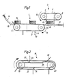
- the preferred embodiment of the feeding arrangement in accordance with the invention which is shown in figure 1 thus comprises a first conveyor 1 and a second conveyor 2 which extend substantially in the same direction, but are displaced in respect of one another, so that the front of the second conveyor is practically adjacent to the tail end of the first conveyor.
- the basic design of the two conveyors 1, 2 is conventional and each of the conveyors thus comprises its endless conveyor belt 3, 4 which in a known manner consists of one or more chains, straps or the like.
- the conveyor belts 3, 4 in each of the conveyors 1, 2 run over conventional end pulleys 5, 6 and 7, 8 respectively.
- One pulley in each conveyor is driven at constant speed by means of an electric motor, not shown, or by means of some other known driving unit.
- the direction of movement of the conveyor 1 is indicated on the drawing by means of an arrow 9, and the direction of movement of the conveyor 2 is indicated by means of an arrow 10.
- the conveyor belt 3, 4 of the first as well as of the second conveyor comprises projecting driving elements 11 and 12 respectively positioned at regular intervals.
- the driving elements 11, 12 are of elongated shape and are arranged substantially right-angled to the surface of the conveyor belt 3, 4.
- Each driving element 11, 12 consists of one or more plates or bars which are positioned at intervals over parts of the total width of the conveyor belt 3, 4.
- the plates or bars forming the driving element 11 are laterally displaced in relation to the bars or plates of the driving element 12, which makes it possible for the driving elements to engage and to pass each other without obstruction in the area where the conveyors 1, 2 meet one another, which will be explained in detail in the following.
- Each driving element 11 on the conveyor belt 3 or each individual unit included in the driving element 11 is provided at the outer end of its front side, seen in the direction of feed, with a curved or convex contact surface 13.
- the length of the driving element 11, that is to say the perpendicular distance between the conveyor belt and the outermost end or contact surface of the driving element in the preferred embodiment of the arrangement in accordance with the invention is greater than the radius of the end pulley 6. More particularly, it is preferred, for reasons which will be explained in more detail in the following, that the driving element 11 should be 1 to 3 times longer than the radius of the end pulley 6.
- the delivery chute 14 is arranged so that its tail end directly adjoins the starting end of the active upper portion of the first conveyor and is provided in the said end with cutouts 16 which make it possible for the driving elements 11 to pass the tail end of the delivery chute 14 without being obstructed.
- the shape and the positioning of the cutouts will be adapted, of course, to the shape and positioning of the driving elements 11 on the conveyor belt 3.
- a device comprising a feeding out surface 17 is present which is situated directly adjoining the tail end of the active portion of the first conveyor and is provided, similarly to the delivery chute 14, with cutouts 18 to permit an unhindered passage of the driving elements 11 of the conveyor belt 3.
- the feeding surface 17 constitutes a direct continuation of the upper, active portion of the first conveyor 1, and the second conveyor 2 extends substantially parallel with the prolongation of the first conveyor 1 as well as with the feeding out ' system 17, the mutual distance between the active portions of the conveyors 1, 2 facing each other being equal to, or slightly greater than, the length of the driving elements 11.
- the partly formed packing containers or objects 15 are delivered to the conveyor 1 via the delivery chute 14 onto which they are fed out from the first machine part.
- the objects 15 slide down the chute 14 by gravity to stop near the end of the chute owing to the diminishing slope of the chute 14.
- one of the driving elements 11, fitted at regular intervals along the conveyor belt 3 will engage with the rear end of the packing container or object 15 and drive the object onto the active portion of the conveyor 1. Thanks to the cutout 16 in the tail end of the delivery chute, the driving element 11 can pass the chute 14 freely and engage with the object 15.
- the object 15 is then moved at a constant speed along the upper, active portion of the conveyor which may be of the required length.
- the conveyed object 15 approaches the tail end of the conveyer 1 (to the right on the drawing), it is to be transferred to the second conveyor 2 which subsequently takes over the driving and at approximately twice the speed of conveyor 1 moves the object to the second processing machine. Since the packing containers are not yet finished, they are very damageable and the transfer between the conveyors working at different speeds therefore has to take place without abrupt increases in speed, jerks or impacts on engagement between the driving elements 12 of the second conveyor moved forward at a relatively high speed and the packing container.
- the driving element of the first conveyor at the end of the first conveyor is tipped forward so that an increase of speed is imparted to the object 15 directly before the feeding is taken over by the second conveyor 2.
- the re-orientation or tipping forward of the actual driving element 11 is brought about in that the conveyor belt 3 is made to change direction of movement when it approaches the end pulley 6.
- the outer end or contact surface 13 of the driving element 11 will thus be given additional speed which, together with the basic speed of the conveyor, will accelerate the moved object 15 so that when it is moved out onto the feeding out surface 17, positioned in the prolongation of the active portion of conveyor 1, it has a linear speed which substantially corresponds to the linear speed of the second conveyor.
- the speed of the object 15 over the feeding out surface 17 can be adapted to the speed of the second conveyor through adjustment of the length of the driving element in relation to the radius of the end pulley 6.
- the principle here is that a driving element 11 of a greater length or an end pulley 6 of a smaller diameter impart a greater increase of linear speed to the object.
- the possible increase of speed is limited by the capacity of the object 15 to endure the acceleration, and it has been found appropriate in the case of packing containers to select a length of driving element which is 1 to 3 times greater than the radius of the end pully 6.
- the driving element 11 will usually extend above the upper limiting surface of the object so that when the driving element is moved along the periphery of the end pulley 6 it slides downwards along the rear limiting surface of the object 15, seen in the direction of movement, at the same time as the object is accelarated to a speed which is approximately twice as great as the linear speed of the conveyor 1, that is to say a speed which substantially corresponds to the linear speed of the conveyor 2.
- the driver 12 of the conveyor belt 4 will come to rest against the object 15 and take over the further movement of the object along the feeding out surface 17.
- the feeding out surface 17 terminates in a feeding in pocket (not shown in the drawing) in the subsequent processing machine, to which the packing containers or objects are thus fed at substantially twice as long intervals as when they are fed out from the first processing machine.
- the conveyor 18 comprises two end pulleys 19, 20 over which passes an endless conveyor belt 21.
- the conveyor belt 21, like the conveyor belt 3 in figure 1, may be in the form of a chain, for example, which carries driving elements 22 fitted at a regular pitch.
- the driving elements 22 are in the form of fingers or arms which are attached to the conveyor belt 21 so that they can swivel about axles 23 which are parallel to one another and parallel to the axes of rotation of the end pulleys 19 and 20.
- Each driving element 22 is provided with an arm or control part 24 projecting on the opposite side of the axle or the conveyor belt 21 which at its end has a roller 25.
- the rollers 25 run along a cam 26 which extends along the whole length of the belt 21.
- the distance between the cam 26 and the conveyor belt 21 is constant, except for the part of the active portion of the conveyor belt 21, where the orientation of the driving element 22 in relation to the direction of movement of the conveyor belt ist to be changed.
- the cam 26 and the conveyor belt 21 draw nearer towards each other, so that the driving elements 22 are tipped forward by the rollers 25 and control parts 24 running along the cam 26 in the direction of movement of the conveyor.
- the required increase of the speed of movement of the conveyed object 15 and the subsequent working moment are obtained, e.g. the transfer of the object 15 to a faster conveyor can take place without hindrance.
- the embodiment of the arrangement described in figure 2 is of a more complicated and hence somewhat more expensive design, it offers certain advantages over the preferred embodiment shown in figure 1, which advantages under certain circumstances can make up for the disadvantages conditioned by the construction.
- the temporary acceleration of the conveyed objects may take place at any desired part of the whole length of the conveyor.
- the course of the acceleration and the total final speed of the object can be controlled very accurately, and independently of such factors as the diameter of the end pulleys, and it is also possible to provide a negative acceleration of the objects, should this be desired.
- a feeding arrangement in accordance with the invention can be combined, of course, with a number of different types of conveyors, and it is also possible to orientate the conveyors in a different manner to that shown in the figures.
- the two conveyors in figure 1 may be arranged following one another in the same plane, for example, the feeding out surface 17 bein omitted and the end pulleys 6, 7 of the two conveyors partly engaging in one another, which can be solved simply in that either the end pulley 6 or the end pulley 7 is in the form of two separate pulleys situated at some distance from each other.
- the conveyor passing over these pulleys must be in the form of two conveyor belts or chains running next to one another.
Applications Claiming Priority (2)
| Application Number | Priority Date | Filing Date | Title |
|---|---|---|---|
| SE8100247A SE8100247L (sv) | 1981-01-19 | 1981-01-19 | Sett och anordning for matning av foremal |
| SE8100247 | 1981-01-19 |
Publications (3)
| Publication Number | Publication Date |
|---|---|
| EP0056946A1 true EP0056946A1 (fr) | 1982-08-04 |
| EP0056946B1 EP0056946B1 (fr) | 1985-05-08 |
| EP0056946B2 EP0056946B2 (fr) | 1989-04-05 |
Family
ID=20342901
Family Applications (1)
| Application Number | Title | Priority Date | Filing Date |
|---|---|---|---|
| EP82100154A Expired EP0056946B2 (fr) | 1981-01-19 | 1982-01-12 | Dispositif d'alimentation en objets |
Country Status (6)
| Country | Link |
|---|---|
| US (1) | US4682684A (fr) |
| EP (1) | EP0056946B2 (fr) |
| JP (1) | JPS57137217A (fr) |
| AU (1) | AU7958882A (fr) |
| DE (1) | DE3263603D1 (fr) |
| SE (1) | SE8100247L (fr) |
Cited By (4)
| Publication number | Priority date | Publication date | Assignee | Title |
|---|---|---|---|---|
| EP0143349A2 (fr) * | 1983-10-28 | 1985-06-05 | Mitsubishi Denki Kabushiki Kaisha | Appareil pour la culture de plantes |
| DE9000612U1 (fr) * | 1990-01-20 | 1990-03-22 | Spang & Brands Maschinenfabrik Gmbh & Co, 6382 Friedrichsdorf, De | |
| FR2691955A1 (fr) * | 1992-03-16 | 1993-12-10 | Lehmann Martin | Convoyeur à séparateur, et utilisation de ce convoyeur. |
| AU724484B2 (en) * | 1996-05-10 | 2000-09-21 | Australian Wool Innovation Limited | Apparatus for spreading a sheet-like article |
Families Citing this family (25)
| Publication number | Priority date | Publication date | Assignee | Title |
|---|---|---|---|---|
| SE468983B (sv) * | 1987-01-22 | 1993-04-26 | Profor Ab | Transportaggregat |
| DE3720804A1 (de) * | 1987-06-24 | 1989-01-12 | Krupp Gmbh | Transporteinrichtung fuer gerundete dosenzargen |
| JPH02233416A (ja) * | 1989-02-20 | 1990-09-17 | Sig (Schweiz Ind Ges) | 物品の分配装置 |
| DE4211658A1 (de) * | 1992-04-07 | 1993-10-14 | Krupp Maschinentechnik | Vorschubeinrichtung für Tafeln |
| US5375824A (en) * | 1993-03-17 | 1994-12-27 | R. R. Donnelley & Sons Company | Selectable pin spacing on gathering chain |
| US5275272A (en) * | 1993-04-06 | 1994-01-04 | Sandvik Process Systems, Inc. | Conveyor system with article diverting mechanism |
| JP3256751B2 (ja) * | 1993-05-06 | 2002-02-12 | 四国化工機株式会社 | 固形物の搬送装置 |
| US5711412A (en) * | 1994-03-07 | 1998-01-27 | Elpatronic Ag | Device for serial transport of sheet metal blanks towards a processing station |
| JP2678577B2 (ja) * | 1994-04-15 | 1997-11-17 | 日設産業機器株式会社 | 青果物の搬送装置 |
| IT1275472B (it) * | 1995-07-04 | 1997-08-07 | Finmeccanica S P A Ora Finmecc | Apparecchiatura per il caricamento di plichi su macchine smistatrici |
| US5699651A (en) * | 1996-05-23 | 1997-12-23 | Riverwood International Corporation | Selector assembly |
| IT237489Y1 (it) * | 1997-05-14 | 2000-09-13 | Finmeccanica Spa | Tappetino rotante con alette di contenimento per apparecchiaturesmistatrici |
| US6134865A (en) * | 1998-02-23 | 2000-10-24 | Longford Equipment International Limited | Paper stack handler |
| US6408602B1 (en) | 1999-07-27 | 2002-06-25 | Mars Incorporated | apparatuses for forming a compressed grouping of objects |
| DE19944780A1 (de) * | 1999-09-17 | 2001-04-19 | Focke & Co | Vorrichtung zum Transport von Gegenständen, insbesondere Zigarettengruppen |
| US6390766B1 (en) | 1999-11-30 | 2002-05-21 | Owens Corning Fiberglas Technology, Inc. | Shingle bundle palletizer with improved metering conveyor, pattern conveyor and shuttle conveyor |
| US6306070B1 (en) | 1999-12-29 | 2001-10-23 | Robert M. Herrin | Apparatus for erecting and sealing flat containers and associated methods |
| ATE467585T1 (de) * | 2005-01-03 | 2010-05-15 | Laitram Llc | Förderanlage mit einem förderband mit schaufeln, einschliesslich segmentierter schaufeln für spaltfreie endübertragung |
| US7537105B2 (en) * | 2005-08-15 | 2009-05-26 | Laitram, L.L.C. | Apparatus and methods for controlling spacing of conveyed objects |
| US20070096369A1 (en) * | 2005-11-01 | 2007-05-03 | Fox Stone, Inc. | Methods and apparatus for the separation of molded products from flexible mold pieces |
| DE102008019028A1 (de) * | 2008-04-15 | 2009-10-22 | Hochland Natec Gmbh | Verfahren und Vorrichtung zum Stapeln verpackter Lebensmittelscheiben |
| US8720671B1 (en) * | 2011-04-08 | 2014-05-13 | Brian Slone | Conveyor system with pivotal flight members |
| EP2955118B1 (fr) * | 2014-06-10 | 2017-07-26 | Tetra Laval Holdings & Finance S.A. | Unité d'alimentation pour alimenter des emballages scellés de produits alimentaires versables |
| EP3009359B1 (fr) * | 2014-10-13 | 2017-07-05 | Tetra Laval Holdings & Finance S.A. | Unité d'alimentation pour alimenter des emballages scellés de produits alimentaires versables |
| CN109094857A (zh) * | 2018-08-16 | 2018-12-28 | 吴让平 | 一种用于食品包装的输送机构以及食品包装设备 |
Citations (2)
| Publication number | Priority date | Publication date | Assignee | Title |
|---|---|---|---|---|
| CH523172A (de) * | 1970-05-04 | 1972-05-31 | Sig Schweiz Industrieges | Vorrichtung zur regelmässigen Abgabe von unregelmässig einlaufenden Gegenständen |
| GB1545058A (en) * | 1976-05-17 | 1979-05-02 | Drg Ltd | Method and apparatus for top-loading articles into containers |
Family Cites Families (9)
| Publication number | Priority date | Publication date | Assignee | Title |
|---|---|---|---|---|
| US3053373A (en) * | 1960-12-01 | 1962-09-11 | Package Machinery Co | Apparatus for the high speed feeding of stacked articles |
| GB1278271A (en) * | 1968-10-10 | 1972-06-21 | Adams Powel Equipment Ltd | Improvements in and relating to machinery for making tiles |
| US3650566A (en) * | 1969-10-24 | 1972-03-21 | Aluminum Co Of America | Machine for arranging cans in position |
| GB1334267A (en) * | 1971-06-30 | 1973-10-17 | Tensor Corp | Apparatus for handling cans |
| US3827211A (en) * | 1973-01-02 | 1974-08-06 | Federal Paper Board Co Inc | Packaging machine |
| JPS5130259U (fr) * | 1974-08-21 | 1976-03-04 | ||
| CH585658A5 (fr) * | 1974-12-19 | 1977-03-15 | Sapal Plieuses Automatiques | |
| JPS5433429A (en) * | 1977-11-04 | 1979-03-12 | Nissan Motor Co Ltd | Seat belt retractor |
| DE2932431A1 (de) * | 1979-08-10 | 1981-02-26 | Rose Verpackungsmasch | Vorrichtung zum vereinzeln und zufuehren von gegenstaenden, insbesondere von bonbons, zu einer verpackungsmaschine |
-
1981
- 1981-01-19 SE SE8100247A patent/SE8100247L/ not_active Application Discontinuation
-
1982
- 1982-01-12 EP EP82100154A patent/EP0056946B2/fr not_active Expired
- 1982-01-12 DE DE8282100154T patent/DE3263603D1/de not_active Expired
- 1982-01-18 AU AU79588/82A patent/AU7958882A/en not_active Abandoned
- 1982-01-18 JP JP57005858A patent/JPS57137217A/ja active Pending
-
1985
- 1985-06-26 US US06/749,115 patent/US4682684A/en not_active Expired - Fee Related
Patent Citations (2)
| Publication number | Priority date | Publication date | Assignee | Title |
|---|---|---|---|---|
| CH523172A (de) * | 1970-05-04 | 1972-05-31 | Sig Schweiz Industrieges | Vorrichtung zur regelmässigen Abgabe von unregelmässig einlaufenden Gegenständen |
| GB1545058A (en) * | 1976-05-17 | 1979-05-02 | Drg Ltd | Method and apparatus for top-loading articles into containers |
Non-Patent Citations (1)
| Title |
|---|
| Dubbel-Taschenbuch fur den Maschinebau, 13. Auflage ber. Neudruck, Band 1, 1974 Springer Verlag *pages 242, 243; fig. 14 * * |
Cited By (7)
| Publication number | Priority date | Publication date | Assignee | Title |
|---|---|---|---|---|
| EP0143349A2 (fr) * | 1983-10-28 | 1985-06-05 | Mitsubishi Denki Kabushiki Kaisha | Appareil pour la culture de plantes |
| EP0143349A3 (fr) * | 1983-10-28 | 1986-10-08 | Mitsubishi Denki Kabushiki Kaisha | Appareil pour la culture de plantes |
| DE9000612U1 (fr) * | 1990-01-20 | 1990-03-22 | Spang & Brands Maschinenfabrik Gmbh & Co, 6382 Friedrichsdorf, De | |
| US5050370A (en) * | 1990-01-20 | 1991-09-24 | Spang & Brands Maschinenfabrik Gmbh & Co. | Device for the packing of weighed quantities of elongated products |
| FR2691955A1 (fr) * | 1992-03-16 | 1993-12-10 | Lehmann Martin | Convoyeur à séparateur, et utilisation de ce convoyeur. |
| US5353916A (en) * | 1992-03-16 | 1994-10-11 | Martin Lehmann | Conveyer apparatus |
| AU724484B2 (en) * | 1996-05-10 | 2000-09-21 | Australian Wool Innovation Limited | Apparatus for spreading a sheet-like article |
Also Published As
| Publication number | Publication date |
|---|---|
| EP0056946B2 (fr) | 1989-04-05 |
| SE8100247L (sv) | 1982-07-20 |
| DE3263603D1 (en) | 1985-06-13 |
| US4682684A (en) | 1987-07-28 |
| EP0056946B1 (fr) | 1985-05-08 |
| JPS57137217A (en) | 1982-08-24 |
| AU7958882A (en) | 1982-07-29 |
Similar Documents
| Publication | Publication Date | Title |
|---|---|---|
| EP0056946B1 (fr) | Dispositif d'alimentation en objets | |
| KR102187249B1 (ko) | 싱귤레이터 컨베이어 | |
| US4676361A (en) | Troughing conveyors for carton or bag orienting and conveying | |
| US5366063A (en) | Accumulator for conveyor system | |
| EP1209106A1 (fr) | Machine et procédé pour transporter des produits | |
| US7581637B2 (en) | Feeding device for a packaging machine | |
| EP0395178A1 (fr) | Méthode et dispositif pour le transfert d'objets d'un premier convoyeur à un deuxième convoyeur, qui est substantiellement perpendiculaire au premier | |
| EP0139775A1 (fr) | Dispositif pour le transport et l'accumulation d'objets | |
| CA2035422A1 (fr) | Systeme de tri et d'alimentation | |
| US5064054A (en) | Overlapping flat surface transport carrier conveyor | |
| WO2020147851A1 (fr) | Dispositif de transport | |
| US6390766B1 (en) | Shingle bundle palletizer with improved metering conveyor, pattern conveyor and shuttle conveyor | |
| US6273238B1 (en) | Apparatus and method for separating adjacent objects on a conveyor | |
| US4354590A (en) | Spacer escalator for spacing loads in carton loading machines | |
| US4880103A (en) | Pressureless conveyor for bottles or similar items | |
| US3620355A (en) | Corner conveyor | |
| GB2170164A (en) | Conveying planar articles | |
| US4526266A (en) | Dual-T transfer conveyor | |
| US4690266A (en) | Belt conveyor having article sorting and orienting features | |
| US4925006A (en) | Conveyor apparatus having means for a shock-free article acceleration | |
| JPS6236932B2 (fr) | ||
| US4795022A (en) | Biscuit conveyor | |
| JPS6144770B2 (fr) | ||
| US3403771A (en) | Container orienting mechanism | |
| CA1196039A (fr) | Montage pour le transfert entre deux convoyeurs, et methode connexe |
Legal Events
| Date | Code | Title | Description |
|---|---|---|---|
| PUAI | Public reference made under article 153(3) epc to a published international application that has entered the european phase |
Free format text: ORIGINAL CODE: 0009012 |
|
| AK | Designated contracting states |
Designated state(s): CH DE FR GB IT LI NL SE |
|
| 17P | Request for examination filed |
Effective date: 19820720 |
|
| ITF | It: translation for a ep patent filed |
Owner name: BARZANO' E ZANARDO MILANO S.P.A. |
|
| GRAA | (expected) grant |
Free format text: ORIGINAL CODE: 0009210 |
|
| AK | Designated contracting states |
Designated state(s): CH DE FR GB IT LI NL SE |
|
| REF | Corresponds to: |
Ref document number: 3263603 Country of ref document: DE Date of ref document: 19850613 |
|
| ET | Fr: translation filed | ||
| PLBI | Opposition filed |
Free format text: ORIGINAL CODE: 0009260 |
|
| 26 | Opposition filed |
Opponent name: SEITZ ENZINGER NOLL MASCHINENBAU AG Effective date: 19860125 |
|
| NLR1 | Nl: opposition has been filed with the epo |
Opponent name: SEITZ ENZINGER NOLL MASCHINENBAU AG |
|
| PLAB | Opposition data, opponent's data or that of the opponent's representative modified |
Free format text: ORIGINAL CODE: 0009299OPPO |
|
| R26 | Opposition filed (corrected) |
Opponent name: SEITZ ENZINGER NOLL MASCHINENBAU AG, MANNHEIM Effective date: 19860125 |
|
| RAP2 | Party data changed (patent owner data changed or rights of a patent transferred) |
Owner name: AB TETRA PAK |
|
| REG | Reference to a national code |
Ref country code: CH Ref legal event code: PFA Free format text: AB TETRA PAK |
|
| NLT2 | Nl: modifications (of names), taken from the european patent patent bulletin |
Owner name: AKTIEBOLAGET TETRA PAK TE LUND, ZWEDEN. |
|
| ITF | It: translation for a ep patent filed |
Owner name: BARZANO' E ZANARDO MILANO S.P.A. |
|
| PUAH | Patent maintained in amended form |
Free format text: ORIGINAL CODE: 0009272 |
|
| STAA | Information on the status of an ep patent application or granted ep patent |
Free format text: STATUS: PATENT MAINTAINED AS AMENDED |
|
| 27A | Patent maintained in amended form |
Effective date: 19890405 |
|
| AK | Designated contracting states |
Kind code of ref document: B2 Designated state(s): CH DE FR GB IT LI NL SE |
|
| PG25 | Lapsed in a contracting state [announced via postgrant information from national office to epo] |
Ref country code: SE Effective date: 19890405 |
|
| ET3 | Fr: translation filed ** decision concerning opposition | ||
| NLR2 | Nl: decision of opposition | ||
| NLR3 | Nl: receipt of modified translations in the netherlands language after an opposition procedure | ||
| ITTA | It: last paid annual fee | ||
| EUG | Se: european patent has lapsed |
Ref document number: 82100154.2 Effective date: 19890628 |
|
| PGFP | Annual fee paid to national office [announced via postgrant information from national office to epo] |
Ref country code: FR Payment date: 19971218 Year of fee payment: 17 |
|
| PGFP | Annual fee paid to national office [announced via postgrant information from national office to epo] |
Ref country code: NL Payment date: 19971222 Year of fee payment: 17 Ref country code: DE Payment date: 19971222 Year of fee payment: 17 |
|
| PGFP | Annual fee paid to national office [announced via postgrant information from national office to epo] |
Ref country code: GB Payment date: 19971223 Year of fee payment: 17 |
|
| PGFP | Annual fee paid to national office [announced via postgrant information from national office to epo] |
Ref country code: CH Payment date: 19980108 Year of fee payment: 17 |
|
| PG25 | Lapsed in a contracting state [announced via postgrant information from national office to epo] |
Ref country code: GB Free format text: LAPSE BECAUSE OF NON-PAYMENT OF DUE FEES Effective date: 19990112 |
|
| PG25 | Lapsed in a contracting state [announced via postgrant information from national office to epo] |
Ref country code: LI Free format text: LAPSE BECAUSE OF NON-PAYMENT OF DUE FEES Effective date: 19990131 Ref country code: CH Free format text: LAPSE BECAUSE OF NON-PAYMENT OF DUE FEES Effective date: 19990131 |
|
| PG25 | Lapsed in a contracting state [announced via postgrant information from national office to epo] |
Ref country code: NL Free format text: LAPSE BECAUSE OF NON-PAYMENT OF DUE FEES Effective date: 19990801 |
|
| GBPC | Gb: european patent ceased through non-payment of renewal fee |
Effective date: 19990112 |
|
| REG | Reference to a national code |
Ref country code: CH Ref legal event code: PL |
|
| PG25 | Lapsed in a contracting state [announced via postgrant information from national office to epo] |
Ref country code: FR Free format text: LAPSE BECAUSE OF NON-PAYMENT OF DUE FEES Effective date: 19990930 |
|
| PG25 | Lapsed in a contracting state [announced via postgrant information from national office to epo] |
Ref country code: DE Free format text: LAPSE BECAUSE OF NON-PAYMENT OF DUE FEES Effective date: 19991103 |
|
| REG | Reference to a national code |
Ref country code: FR Ref legal event code: ST |