EP0056925A1 - Device for measuring by means of gamma radiation - Google Patents
Device for measuring by means of gamma radiation Download PDFInfo
- Publication number
- EP0056925A1 EP0056925A1 EP81630085A EP81630085A EP0056925A1 EP 0056925 A1 EP0056925 A1 EP 0056925A1 EP 81630085 A EP81630085 A EP 81630085A EP 81630085 A EP81630085 A EP 81630085A EP 0056925 A1 EP0056925 A1 EP 0056925A1
- Authority
- EP
- European Patent Office
- Prior art keywords
- block
- axis
- radiation
- box
- orifices
- Prior art date
- Legal status (The legal status is an assumption and is not a legal conclusion. Google has not performed a legal analysis and makes no representation as to the accuracy of the status listed.)
- Ceased
Links
- 230000005855 radiation Effects 0.000 title claims abstract description 14
- 238000009434 installation Methods 0.000 claims abstract description 13
- 238000005259 measurement Methods 0.000 claims abstract description 8
- 230000005251 gamma ray Effects 0.000 claims abstract description 4
- 230000001681 protective effect Effects 0.000 claims abstract description 4
- 230000002285 radioactive effect Effects 0.000 claims abstract description 4
- 239000012809 cooling fluid Substances 0.000 claims description 2
- 238000010521 absorption reaction Methods 0.000 claims 1
- 230000007547 defect Effects 0.000 description 2
- 238000004519 manufacturing process Methods 0.000 description 2
- 230000005484 gravity Effects 0.000 description 1
- 238000000746 purification Methods 0.000 description 1
- 239000011435 rock Substances 0.000 description 1
- 238000005096 rolling process Methods 0.000 description 1
Images
Classifications
-
- G—PHYSICS
- G01—MEASURING; TESTING
- G01B—MEASURING LENGTH, THICKNESS OR SIMILAR LINEAR DIMENSIONS; MEASURING ANGLES; MEASURING AREAS; MEASURING IRREGULARITIES OF SURFACES OR CONTOURS
- G01B15/00—Measuring arrangements characterised by the use of electromagnetic waves or particle radiation, e.g. by the use of microwaves, X-rays, gamma rays or electrons
- G01B15/02—Measuring arrangements characterised by the use of electromagnetic waves or particle radiation, e.g. by the use of microwaves, X-rays, gamma rays or electrons for measuring thickness
Definitions
- the present invention relates to an installation for measuring by gamma-ray measurement, in particular for measuring in connection with the control of the thickness of laminated products.
- the aim of the present invention was to propose a gamma-ray measurement installation which meets on the one hand the analytical needs which exist in the production units in question, in particular by allowing the use of several radioactive sources of different powers and which allow on the other hand, control work free of risks for the operator.
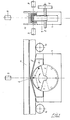
- a block (1) movable around an eccentric axis (2) is equipped with several sources (3) of radioactive radiation which are arranged on the circumference of said block, the latter being housed in a basic box (4), surmounted by a protective cover (5) which has orifices (6) to allow passage to radiation, that the axis (2) is coupled to a servo -motor (7) capable of driving the block (1) in a determined position of the sources (3) relative to the orifice (6) and that radiation detectors (9) are arranged opposite the orifices (6) to a sufficient distance to allow the product to be scanned to be interposed.
- the block is retractable in the hollow of the box and it remains excited until it is stressed by the action of the servo-motor. So in case of rest, when there is no analytical work to be done, simply disconnect the servo motor system, to ensure that the block rocks in the hollow of the box, since it is movable around of its axis and that the sources In the absence of action exerted by the servo-motor, which can also occur in the event of a power failure, any risk of accident is ruled out, since the block automatically retracts, by its only gravity .
- the block (1) which presents the plane perpendicular to its axis (2), the shape of a sector of a circle, the arc of which is less than 180 °. Thanks to this feature, it is ensured that the normal position of the block, which is not stressed by any force, is the low position, shown in dotted lines.
- the sources (3) are arranged along the periphery of the block. They are usefully of different powers.
- the axis (2) corresponds substantially to the center of the circle sector delimited by the block.
- the axis (2) is usefully disposed below the upper edges of the box (4), so that in the event of tilting, the block is completely immersed in the box (4).
- the cover (5) of the protection has holes (6).
- radiation detectors (9) are fixedly arranged opposite the orifices (6).
- Another particular feature of the installation according to the invention consists in that the protective cover (5) which delimits a chamber (8) usefully contains a cooling fluid which contributes to the radiation protection by absorbing part of it. this.
- the installation can easily be arranged between two rollers (10) of a train which moves a rolled product (11).
- the axes of the rollers (10) are parallel to the axis (2) of the block (1).
- the measurement results provide information relating either to the section of the product (thicknesses, heights, widths, section, symmetry), or to the degree of linear regularity by following a predetermined trace.
- the information collected by the measurement sensors is reconstructed in the microprocessor and used to check the section, dimensions or defects of the product. Likewise it becomes possible to calculate the metric weight resp. the total weight of the rolled product. These measured and calculated quantities are compared with those of a reference product and any variation in relation to this is signaled to the operator and / or introduced into the dynamic regulation circuit of the rolling mill train.
- the microprocessor can also receive the following signals: train speed, product temperature, product length.
- the microsystem can thus calculate the dimensions, the section, the extent of the defects, the symmetry, the metric weight and the total weight of the product inspected. Any deviation from the reference is recorded, reported to the operator and if necessary introduced into the dynamic train control loop.
Landscapes
- Physics & Mathematics (AREA)
- Electromagnetism (AREA)
- General Physics & Mathematics (AREA)
- Length-Measuring Devices Using Wave Or Particle Radiation (AREA)
- Analysing Materials By The Use Of Radiation (AREA)
Abstract
Une installation de mesure par gammamétrie, notamment en rapport avec le contrôle de l'épaisseur de produits laminés, prévoit qu'un bloc (1) mobile autour d'un axe (2) excentrique est équipé de plusieurs sources (3) de rayonnement radioactif qui sont disposées sur la circonférence dudit bloc, ce dernier étant logé dans un caisson (4) de base, surmonté d'un capot (5) de protection qui comporte des orifices (6) pour livrer passage au rayonnement, que l'axe (22) est accouplé à un servo-moteur (7) capable d'entraîner le bloc (1) en position déterminée des sources (3) par rapport à l'orifice (6), et que des détecteurs (9) de rayonnement sont disposés en face des orifices (6) à une distance suffisante pour permettre d'interposer le produit à scruter. L'ensemble block (1)/ caisson (4)/ capot (5) est disposé entre deux rouleaux (10) d'un train qui déplace un produit (11) laminé. Le bloc (1) présente dans le plan perpendiculaire à l'axe (2) la forme d'un secteur de cercle, dont l'arc est de préférence inférieur à 180°; l'axe (2) correspondant au centre dudit cercle est disposé en-dessous des bords supérieurs du caisson.A gamma-ray measurement installation, in particular in connection with the control of the thickness of laminated products, provides that a block (1) movable around an eccentric axis (2) is equipped with several sources (3) of radioactive radiation. which are arranged on the circumference of said block, the latter being housed in a base box (4), surmounted by a protective cover (5) which has orifices (6) to allow passage to radiation, that the axis ( 22) is coupled to a servo motor (7) capable of driving the block (1) in a determined position of the sources (3) relative to the orifice (6), and that radiation detectors (9) are arranged opposite the orifices (6) at a sufficient distance to allow the product to be scanned to be interposed. The block (1) / box (4) / cover (5) assembly is arranged between two rollers (10) of a train which moves a rolled product (11). The block (1) has in the plane perpendicular to the axis (2) the shape of a sector of a circle, the arc of which is preferably less than 180 °; the axis (2) corresponding to the center of said circle is arranged below the upper edges of the box.
Description
La présente invention concerne une installation de mesure par gammamétrie, notamment de mesure en rapport avec le contrôle de l'épaisseur de produits laminés.The present invention relates to an installation for measuring by gamma-ray measurement, in particular for measuring in connection with the control of the thickness of laminated products.
Il est connu d'avoir recours à la gammamétrie pour mesurer l'épaisseur des produits laminés les plus divers. Or les responsables des unités de production où des mesures gammamétriques seraient-a envisager, hésitent souvent avant de se lancer dans la pratique de ce mode analytique et ceci avant tout pour des raisons de sécurité.It is known to use gamma measurement to measure the thickness of the most diverse laminated products. However, the managers of production units where gamma measurements should be considered, often hesitate before embarking on the practice of this analytical mode and this above all for safety reasons.
Le but de la présente invention était de proposer une installation de mesure par gammamétrie répondant d'une part aux besoins analytiques qui existent dans les unités de production en question, en permettant notamment l'utilisation de plusieures sources radioactives de puissances différentes et qui permettent d'autre part un travail de contrôle exempt de risques pour l'opérateur.The aim of the present invention was to propose a gamma-ray measurement installation which meets on the one hand the analytical needs which exist in the production units in question, in particular by allowing the use of several radioactive sources of different powers and which allow on the other hand, control work free of risks for the operator.
Ce but est atteint par l'installation suivant l'invention qui prévoit notamment qu'un bloc (1) mobile autour d'un axe (2) excentrique est équipé de plusieures sources (3) de rayonnement radioactif qui sont disposées sur la circonférence dudit bloc, ce dernier étant logé dans un caisson (4) de base, surmonté d'un capot (5) de protection qui comporte des orifices (6) pour livrer passage au rayonnement, que l'axe (2) est accouplé à un servo-moteur (7) capable d'entraîner le bloc (1) en position déterminée des sources (3) par rapport à l'orifice (6) et que des détecteurs (9) de rayonnement sont disposés en face des orifices (6) à une distance suffisante pour permettre d'interposer le produit à scruter.This object is achieved by the installation according to the invention which provides in particular that a block (1) movable around an eccentric axis (2) is equipped with several sources (3) of radioactive radiation which are arranged on the circumference of said block, the latter being housed in a basic box (4), surmounted by a protective cover (5) which has orifices (6) to allow passage to radiation, that the axis (2) is coupled to a servo -motor (7) capable of driving the block (1) in a determined position of the sources (3) relative to the orifice (6) and that radiation detectors (9) are arranged opposite the orifices (6) to a sufficient distance to allow the product to be scanned to be interposed.
Comme on peut le constater, le bloc est escamotable dans le creux du caisson et il reste excamoté tant qu'il n'est pas sollicité par action du servo-moteur. Ainsi en cas de repos, lorsqu'il n'y a pas de travail analytique à effectuer, il suffit de débrancher le système servo-moteur, pour assurer que le bloc bascule dans le creux du caisson, étant donné qu'il est mobile autour de son axe et que les sources En l'absence d'action excercée par le servo-moteur, ce qui peut également se présenter en cas de panne d'électricité, tout risque d'accident est écarté, étant donné que le bloc s'excamote automatiquement, par sa seule gravité.As can be seen, the block is retractable in the hollow of the box and it remains excited until it is stressed by the action of the servo-motor. So in case of rest, when there is no analytical work to be done, simply disconnect the servo motor system, to ensure that the block rocks in the hollow of the box, since it is movable around of its axis and that the sources In the absence of action exerted by the servo-motor, which can also occur in the event of a power failure, any risk of accident is ruled out, since the block automatically retracts, by its only gravity .
D'autres caractéristiques et avantages ressortiront de la description du dessin qui représente de manière non-limitative une forme d'exécution possible de l'installation suivant l'invention.Other characteristics and advantages will emerge from the description of the drawing which non-limitatively represents a possible embodiment of the installation according to the invention.
On distingue le bloc (1) qui présente le plan perpendiculaire à son axe (2), la forme d'un secteur de cercle, dont l'arc est inférieur à 180°. Grâce à cette particularité il est assuré que la position normale du bloc non-sollicité par une force quelconque, est la position basse, représenteé en pointillé. Les sources (3) sont disposées le long du pourtour du bloc. Elles sont utilement de puissances différentes. L'axe (2) correspond sensiblement au centre du secteur de cercle délimité par le bloc.We can see the block (1) which presents the plane perpendicular to its axis (2), the shape of a sector of a circle, the arc of which is less than 180 °. Thanks to this feature, it is ensured that the normal position of the block, which is not stressed by any force, is the low position, shown in dotted lines. The sources (3) are arranged along the periphery of the block. They are usefully of different powers. The axis (2) corresponds substantially to the center of the circle sector delimited by the block.
On constate que l'axe (2) est utilement disposé en-dessous des bords supérieurs du caisson (4), si bien qu'en cas de basculement, le bloc est totalement immergé dans le caisson (4).It can be seen that the axis (2) is usefully disposed below the upper edges of the box (4), so that in the event of tilting, the block is completely immersed in the box (4).
Le capot (5) du protection comporte des orifices (6). En réglant les servo-moteur (7) on arrive à disposer le bloc (1) de manière adéquate pour assurer qu'une source (3) se trouve exactement en face de l'orifice (6) voulu, si bien que l'on peut diriger un rayonnement de puissance déterminée dans une direction déterminée elle-aussi.The cover (5) of the protection has holes (6). By adjusting the servo-motors (7) we manage to arrange the block (1) adequately to ensure that a source (3) is exactly opposite the orifice (6) desired, so that we can direct a radiation of determined power in a determined direction also.
Il est bien entendu que des détecteurs (9) de rayonnement sont disposés de manière fixe en face des orifices (6).It is understood that radiation detectors (9) are fixedly arranged opposite the orifices (6).
Une autre particularité de l'installation suivant l'invention consiste en ce que le capot (5) de protection qui délimite une chambre (8) contient utilement un fluide de refroidissement qui participe à la protection anti-rayonnement en absorbant une partie de celui-ci.Another particular feature of the installation according to the invention consists in that the protective cover (5) which delimits a chamber (8) usefully contains a cooling fluid which contributes to the radiation protection by absorbing part of it. this.
Comme on peut le constater, l'installation. peut facilement être disposée entre deux rouleaux (10) d'un train qui déplace un produit laminé (11). Dans la disposition représentée les axes des rouleaux (10) sont parallèles à l'axe (2) du bloc (1).As can be seen, the installation. can easily be arranged between two rollers (10) of a train which moves a rolled product (11). In the arrangement shown, the axes of the rollers (10) are parallel to the axis (2) of the block (1).
Il est bien entendu que l'on utilisera un système électronique de gestion et de réglage de l'installation; p. ex. un microprocesseur adéquat auquel sont raccordées les commandes du servo-moteur (7) ainsi que les détecteurs (9).It is understood that an electronic system for managing and adjusting the installation will be used; p. ex. a suitable microprocessor to which the servo motor controls (7) and the detectors (9) are connected.
Les résultats des mesures fournissent des informations relatives soit à la section du produit (épaisseurs, hauteurs, largeurs, section, symétrie), soit au degré de régularité linéaire en suivant une trace prédéterminée.The measurement results provide information relating either to the section of the product (thicknesses, heights, widths, section, symmetry), or to the degree of linear regularity by following a predetermined trace.
Les informations recueillies par les capteurs de mesure sont reconstituées dans le microprocesseur et exploitées en contrôle de section, de dimensions ou de défauts du produit. De même il devient possible de calculer le poids métrique resp. le poids total du produit laminé. Ces grandeurs mesurées et calculées sont comparées à celles d'un produit de référence et toute variation par rapport à celui-ci est signalée à l'opérateur et/ou introduite dans le circuit de régulation dynamique du train de laminoir.The information collected by the measurement sensors is reconstructed in the microprocessor and used to check the section, dimensions or defects of the product. Likewise it becomes possible to calculate the metric weight resp. the total weight of the rolled product. These measured and calculated quantities are compared with those of a reference product and any variation in relation to this is signaled to the operator and / or introduced into the dynamic regulation circuit of the rolling mill train.
Le microprocesseur peut recevoir en plus les signaux suivants: cadence du train, température du produit, longueur du produit.The microprocessor can also receive the following signals: train speed, product temperature, product length.
Après épuration ces signaux sont traités par le micro-système équipé des moyens de dialogue et d'édition usuels.After purification these signals are processed by the micro-system equipped with the usual dialogue and editing means.
Le microsystème peut ainsi calculer les dimensions, la section, l'envergure des défauts, la symétrie, le poids métrique et le poids total du produit inspecté. Tout écart par rapport à la référence est enregistré, signalé à l'opérateur et le cas échéant introduit dans la boucle de régulation dynamique du train.The microsystem can thus calculate the dimensions, the section, the extent of the defects, the symmetry, the metric weight and the total weight of the product inspected. Any deviation from the reference is recorded, reported to the operator and if necessary introduced into the dynamic train control loop.
Claims (5)
Applications Claiming Priority (2)
| Application Number | Priority Date | Filing Date | Title |
|---|---|---|---|
| LU83083 | 1981-01-23 | ||
| LU83083A LU83083A1 (en) | 1981-01-23 | 1981-01-23 | GAMMETRY MEASUREMENT INSTALLATION |
Publications (1)
| Publication Number | Publication Date |
|---|---|
| EP0056925A1 true EP0056925A1 (en) | 1982-08-04 |
Family
ID=19729567
Family Applications (1)
| Application Number | Title | Priority Date | Filing Date |
|---|---|---|---|
| EP81630085A Ceased EP0056925A1 (en) | 1981-01-23 | 1981-12-29 | Device for measuring by means of gamma radiation |
Country Status (4)
| Country | Link |
|---|---|
| US (1) | US4435643A (en) |
| EP (1) | EP0056925A1 (en) |
| JP (1) | JPS57142506A (en) |
| LU (1) | LU83083A1 (en) |
Cited By (1)
| Publication number | Priority date | Publication date | Assignee | Title |
|---|---|---|---|---|
| CN111174746A (en) * | 2019-12-31 | 2020-05-19 | 朱涛 | Split type bearing bush workpiece arc degree detection equipment after bending |
Families Citing this family (2)
| Publication number | Priority date | Publication date | Assignee | Title |
|---|---|---|---|---|
| US4928257A (en) * | 1988-01-25 | 1990-05-22 | Bethlehem Steel Corporation | Method and apparatus for monitoring the thickness profile of a strip |
| US4951222A (en) * | 1988-06-09 | 1990-08-21 | Bethlehem Steel Corporation | Method and system for dimensional and weight measurements of articles of manufacture by computerized tomography |
Citations (4)
| Publication number | Priority date | Publication date | Assignee | Title |
|---|---|---|---|---|
| DE1614361B2 (en) * | 1966-04-07 | 1976-01-15 | Reactor Centrum Nederland (Stichting), Den Haag (Niederlande) | LATCH FOR SHIELDING RADIOACTIVE RADIATION |
| JPS5241550A (en) * | 1975-09-29 | 1977-03-31 | Fuji Electric Co Ltd | Radiation source device for a radiation thickness gauge |
| US4140906A (en) * | 1977-07-08 | 1979-02-20 | Seaman Nuclear Corporation | Density meter |
| US4150289A (en) * | 1977-05-26 | 1979-04-17 | Magnaflux Corporation | Gamma ray calibration system |
Family Cites Families (1)
| Publication number | Priority date | Publication date | Assignee | Title |
|---|---|---|---|---|
| JPS5266455U (en) * | 1975-11-12 | 1977-05-17 |
-
1981
- 1981-01-23 LU LU83083A patent/LU83083A1/en unknown
- 1981-12-29 EP EP81630085A patent/EP0056925A1/en not_active Ceased
-
1982
- 1982-01-21 JP JP57006894A patent/JPS57142506A/en active Granted
- 1982-01-21 US US06/341,231 patent/US4435643A/en not_active Expired - Fee Related
Patent Citations (4)
| Publication number | Priority date | Publication date | Assignee | Title |
|---|---|---|---|---|
| DE1614361B2 (en) * | 1966-04-07 | 1976-01-15 | Reactor Centrum Nederland (Stichting), Den Haag (Niederlande) | LATCH FOR SHIELDING RADIOACTIVE RADIATION |
| JPS5241550A (en) * | 1975-09-29 | 1977-03-31 | Fuji Electric Co Ltd | Radiation source device for a radiation thickness gauge |
| US4150289A (en) * | 1977-05-26 | 1979-04-17 | Magnaflux Corporation | Gamma ray calibration system |
| US4140906A (en) * | 1977-07-08 | 1979-02-20 | Seaman Nuclear Corporation | Density meter |
Non-Patent Citations (1)
| Title |
|---|
| PATENT ABSTRACTS OF JAPAN, Vol. 1, No. 108, 22 Septembre 1977 page 3803E77 & JP-A-52-41550 * |
Cited By (2)
| Publication number | Priority date | Publication date | Assignee | Title |
|---|---|---|---|---|
| CN111174746A (en) * | 2019-12-31 | 2020-05-19 | 朱涛 | Split type bearing bush workpiece arc degree detection equipment after bending |
| CN111174746B (en) * | 2019-12-31 | 2021-09-10 | 南通和力磁材有限公司 | Split type bearing bush workpiece arc degree detection equipment after bending |
Also Published As
| Publication number | Publication date |
|---|---|
| US4435643A (en) | 1984-03-06 |
| JPH027402B2 (en) | 1990-02-19 |
| LU83083A1 (en) | 1982-09-10 |
| JPS57142506A (en) | 1982-09-03 |
Similar Documents
| Publication | Publication Date | Title |
|---|---|---|
| JPH0224018A (en) | Precise cutter with automatic pressure control mechanism | |
| GB2114770A (en) | Telemetry device | |
| US4567798A (en) | Apparatus to maximize saw blade stiffness | |
| EP0056925A1 (en) | Device for measuring by means of gamma radiation | |
| KR20000005407A (en) | System and method for using xchlday diffraction to detect subsurface crystallographic structure | |
| US3867990A (en) | Weighing apparatus for truck and vehicle loads | |
| DE19754321A1 (en) | Unbalance determination method and unbalance measuring device | |
| EP0055569A3 (en) | Distance measuring system | |
| CN211758893U (en) | Novel electric saw | |
| DE10108955C2 (en) | Method for determining the degree of wear of a lens arrangement in a laser processing head and laser processing head | |
| US3974889A (en) | Axle weighing of road vehicles | |
| US5469629A (en) | Brake rotor thickness measurement gage | |
| DE10022568A1 (en) | Exposed object monitor has aircraft mounted thermal camera with location system can correct for position | |
| US5788432A (en) | Method and apparatus for computing allowable spindle rotation speed | |
| CN210119192U (en) | Rolling bearing angular play detection device | |
| JPS578402A (en) | Checking device for aspherical shape | |
| JP3009098B2 (en) | Vehicle load measuring device | |
| CN212964670U (en) | Tire material splicing quality detection device | |
| CA1277445C (en) | Nuclear radiation apparatus and method for dynamically measuring density of test materials during compaction | |
| CN218613150U (en) | Clamping inspection device for machining shaft parts of numerical control lathe | |
| US4780607A (en) | Laser beam power monitoring arrangement | |
| CN108216399A (en) | For the detection device of caterpillar, detection method and caterpillar | |
| JPH04500781A (en) | Method and device for measuring cutting forces of machine tools | |
| JPS6085823A (en) | Gear shaper with relieving interference detecting function | |
| JPS6381204A (en) | Diagnostic device for trimmer shearing state |
Legal Events
| Date | Code | Title | Description |
|---|---|---|---|
| PUAI | Public reference made under article 153(3) epc to a published international application that has entered the european phase |
Free format text: ORIGINAL CODE: 0009012 |
|
| AK | Designated contracting states |
Designated state(s): AT BE CH DE FR GB IT NL SE |
|
| 17P | Request for examination filed |
Effective date: 19830120 |
|
| STAA | Information on the status of an ep patent application or granted ep patent |
Free format text: STATUS: THE APPLICATION HAS BEEN REFUSED |
|
| 18R | Application refused |
Effective date: 19850725 |
|
| RIN1 | Information on inventor provided before grant (corrected) |
Inventor name: JUNCK, GUY |