EP0056552B2 - Tube radiogène comportant un limiteur universel de rayonnement secondaire - Google Patents
Tube radiogène comportant un limiteur universel de rayonnement secondaire Download PDFInfo
- Publication number
- EP0056552B2 EP0056552B2 EP81402080A EP81402080A EP0056552B2 EP 0056552 B2 EP0056552 B2 EP 0056552B2 EP 81402080 A EP81402080 A EP 81402080A EP 81402080 A EP81402080 A EP 81402080A EP 0056552 B2 EP0056552 B2 EP 0056552B2
- Authority
- EP
- European Patent Office
- Prior art keywords
- limiter
- ray tube
- envelope
- radiation
- secondary radiation
- Prior art date
- Legal status (The legal status is an assumption and is not a legal conclusion. Google has not performed a legal analysis and makes no representation as to the accuracy of the status listed.)
- Expired - Lifetime
Links
Images
Classifications
-
- H—ELECTRICITY
- H01—ELECTRIC ELEMENTS
- H01J—ELECTRIC DISCHARGE TUBES OR DISCHARGE LAMPS
- H01J35/00—X-ray tubes
- H01J35/02—Details
- H01J35/16—Vessels; Containers; Shields associated therewith
-
- G—PHYSICS
- G21—NUCLEAR PHYSICS; NUCLEAR ENGINEERING
- G21K—HANDLING OF PARTICLES OR IONISING RADIATION NOT OTHERWISE PROVIDED FOR; IRRADIATION DEVICES; GAMMA RAY OR X-RAY MICROSCOPES
- G21K1/00—Arrangements for handling particles or ionising radiation, e.g. focusing or moderating
- G21K1/02—Arrangements for handling particles or ionising radiation, e.g. focusing or moderating using diaphragms, collimators
Definitions
- the present invention relates to a universal secondary radiation limiter in an X-ray tube. It finds its application both in classical radiology and in radiotherapy.
- a suitable target When a suitable target is bombarded by a fast flux of electrons, it emits a certain flux of photons in a spectral band related to the nature and the geometry of the target and related to the speed of the electrons.
- Such generating devices are called X-ray tubes. They emit more particularly in the X-ray or y-ray band. It is also possible to use secondary photonic emissions. In all cases, the focal point is the material area emitting radiation.
- a ray belonging to the primary radiation can be defined as a direct ray which is carried by a straight line cutting the central axis of the solid angle of the useful radiation at a point common to all the primary rays on the central axis of the primary radiation.
- a secondary ray is carried by any straight line coming from the transmitting focus. This radiation, often of weak energy compared to the primary radiation, generates bad images in Radiology and parasitic irradiation causes in Radiotherapy. It should therefore be deleted as completely as possible.
- a patent US-A-4,157,476 describes an X-ray apparatus comprising an X-ray tube, mounted in a protective envelope in which circulates a fluid used to cool the X-ray tube.
- the protective sheath is made of a material absorbing radiation, and has an opening allowing the passage of an X-ray beam emitted by a focal point formed on an anode of the X-ray tube.
- a conical sheath, made of an X-ray absorbing material is disposed in said opening and through the protective sheath from the outside of the latter up near the X-ray tube, facing said focal point, so as to constitute a beam limiting device.
- the present invention proposes placing a secondary radiation limiter in the X-ray tube in the immediate vicinity of the emitting focus.
- the collimators whose cross section is in the form of a grid or a grid, leave a trace by absorbing primary radiation in the field of the useful beam.
- an X-ray source is described associated with a sample analysis device further comprising a window structure, that is to say a chamber or the tubular element of frusto-conical shape pointed in the immediate vicinity of the focus of the X-ray target on which the primary electron beam is focused.
- This tubular chamber allows the useful X-ray beam to be directed radially but does not make it possible to eliminate or at least reduce the secondary radiation because no means is provided for this purpose.
- the present invention to remedy these drawbacks of the prior art, is a secondary radiation limiter of simple conical shape, one end of which is fixed to the outlet window of the tube and the other close to the focal point emitting the radiation.
- Secondary radiation may not be emitted only from the home. Indeed, the focus is the area bombarded by the electrons incident on the anode. A certain amount of electrons is emitted from the hearth. These electrons are called secondary electrons. They are expelled from the home with some kinetic energy and are attracted due to the anode potential. They therefore fall on it outside the focus, with an energy such that they also produce secondary radiation but outside the focus, that is to say extrafocal.
- an X-ray tube comprising a vacuum-tight enclosure containing an anode which has a focal point emitting a useful beam of radiation, and a secondary radiation limiter consisting of an insulating and refractory shell of predetermined thickness of shape. conical, the axis of symmetry of which is aligned with the central axis of the useful radiation beam and made of a material comprising at least one element with a high atomic number so as to absorb secondary radiation, a limiter including the inlet opening of the envelope is located in the immediate vicinity of the emitting source and the outlet opening of which is linked by means of connection to an outlet window for the useful radiation beam.
- the invention is illustrated by the description of a few X-ray tubes fitted with such limiters.
- the exemplary embodiments are more particularly drawn from radiology but also find their application in radiotherapy.
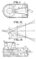
- the X-ray tube shown has a rotating anode 1 included in a vacuum-tight envelope 2. It also includes inside the envelope 2 a photon exciter which is here an electron gun not shown. The flow of electrons strikes the rotating anode 1, at the focal point 4 emitting the flow of photons.
- the secondary radiation limiter 5 comprises a divergent conqiue envelope 6 of axis of symmetry aligned with the axis 7 of the useful field selected. This limiter 5 has an inlet opening 8 for the photon flux and an outlet opening 9 for the useful radiation.
- the outlet opening is mechanically linked to the outlet window 10 of the tube.
- This may include an additional filtration window 11 made of a thin sheet of aluminum or beryllium. This additional filtration has a cumulative effect with the limiter, by absorbing less energetic rays therefore by further depleting the rate of secondary radiation relative to the useful radiation.
- the mechanical connection means 12 of the outlet opening 9 to the outlet window 10 comprise a ring 13 brazed or welded to a fold in the wall of the envelope 2.
- the inlet opening 8 is placed in the immediate vicinity of the emitting focus 4 of the photon flux.
- the projection of the opening 8 on the anode 1 can contain or be contained by the surface of the hearth 4. This characteristic can make it possible to reduce the extent of the emitting hearth or to select, by construction of the tube, a zone of good show.
- the limiter To be absorbing X photons, the limiter must be made of a material based on a chemical element with a high atomic number. The material must be electrically insulating so as not to induce potential differences with the anode and therefore modify the field lines in the tube. It must also be refractory, since it is placed near the hearth which is a very hot source.
- the limiter according to the invention consists of a material based on uranium, hafnium or thorium which meet the three qualities mentioned.
- the material can be an oxide of the three chemical elements mentioned above. It can also consist of a substrate covered with such oxides.
- the mechanical connection means comprise a ring 13 made of an alloy such as for example the Dilver P or the Vacrion 10 in the case of an envelope made of stainless steel or copper.
- FIG. 2 a focal point emitting photons AB has been shown in the half-space to the right of the line carrying the focal point AB.
- the mediating line X is the axis of symmetry of the figure.
- a schematic representation of a secondary radiation limiter CDEF is shown, the inlet and outlet openings of which are CD and EF respectively.
- the primary radiation is included in the space limited by the lines GY and GZ, the point G being a point on the axis X of symmetry.
- a primary radius is therefore defined as a line of this space passing through G.
- the lines GY and GZ are the lines which carry the sides CE and DF of the limiter. They intercept the edges A and B of the hearth AB in the figure, but they can also cut the interior of the hearth by selecting a fraction.
- the secondary radiation comprises all the rays carried by the straight lines coming from the focal point AB and which do not pass through the point G. If the walls CE and DF are absorbing the secondary radiation, the two zones of the space included between the straight lines BC and BE and the wall CE on the one hand, and the lines AD and AF and the wall DF on the other hand, are devoid of any secondary radiation. On the other hand, the zones of the space comprised between the lines BA and BC on the one hand and the lines AB and AD on the other hand each comprise secondary radiation. To reduce it, the CD inlet opening of the CDEF limiter should be brought closer to the AB hearth.
- the extrafocal X-ray radiation is also considerably reduced.
- an electron is re-emitted on the curve e. It hits the target at point H, outside the focus.
- the rays of the sector of the space between the HD and HF rays emitted by the point H, called extrafocal rays are intercepted and absorbed by the wall DF of the limiter.
- the approximation of the entry face CD of the focal point AB, as well as the enlargement of the limiter on the axis GX make it possible to reduce the share of extrafocal radiation in the useful X-ray beam.
- FIG. 3 a tube with a fixed anode with a well has been shown.
- the tube comprises a cathode 15 provided with a filament 16 and a concentrator 17.
- An electron beam 18 penetrates into the well 19 of a fixed anode 20.
- This anode comprises an emissive target 21 of photons and is pierced with a window 22 for the exit of the radiation.
- a limiter 23 according to the invention is arranged in a neck 24 of the casing 14 of the tube. Its inlet opening is arranged opposite the window 22 of the fixed anode 20 and its outlet opening is linked as previously indicated to the radiation outlet window 25 with or without an additional filter.
- the well 19 of the anode also participates in the reduction of the secondary radiation. It may therefore be useful to cover the wells 19 externally with a material as previously described to absorb the secondary radiation.
- An X-ray tube provided with such a secondary radiation limiter has the advantage of bringing the emitting focus closer to the irradiated object without the intermediary of an external collimation chamber as described in the prior art.
- the reduction in secondary radiation is considerably improved thanks to the approximation of the input face of the limiter of the emitting focus.
- the emitting focal point can be constituted by an electron target but also by a target bombarded by incident photons which by Compton effect induce a new flux of photons in an improved spectral band according to a given emission diagram.
- the limiter according to the invention has been described of the divergent type. It is possible to make it in the form of a converging cone, the inlet opening then being larger than the outlet opening without the main characters of the invention being changed.
- the limiter according to the invention can therefore be adapted to any type of small focal tube, thus being a universal limiter of secondary radiation.
Landscapes
- Physics & Mathematics (AREA)
- Spectroscopy & Molecular Physics (AREA)
- Engineering & Computer Science (AREA)
- General Engineering & Computer Science (AREA)
- High Energy & Nuclear Physics (AREA)
- X-Ray Techniques (AREA)
- Radiation-Therapy Devices (AREA)
Description
- La présente invention concerne un limiteur universel de rayonnement secondaire dans un tube radiogène. Elle trouve son application tant en radiologie classique qu'en radiothérapie.
- Quand une cible convenable est bombardée par un flux d'électrons rapides, elle émet un certain flux de photons dans une bande spectrale liée à la nature et à la géométrie de la cible et liée à la vitesse des électrons. De tels dispositifs générateurs sont dits tubes radiogènes. Ils émettent plus particulièrement dans la bande des rayons X ou y. Il est aussi possible d'utiliser des émissions photoniques secondaires. Dans tous les cas, on appelle foyer la zone matérielle émissive des rayonnements.
- Dans la répartition géométrique du flux des photons engendrés, il est connu d'isoler par des moyens divers un angle solide divergent ou non, dont une section contient le foyer émetteur et qui comporte le rayonnement caractérisé d'utile soit qu'il y soit particulièrement monochromatique soit qu'il y soit d'énergie plus élevée que n'importe où ailleurs. Du fait que la source émissive est un foyer étendu, il vient que le rayonnement utile comporte deux parties:
- un rayonnement primaire,
- un rayonnement secondaire.
- Un rayon appartenant au rayonnement primaire peut être défini comme un rayon direct qui est porté par une droite coupant l'axe central de l'angle solide du rayonnement utile en un point commun à tous les rayons primaires sur l'axe central du rayonnement primaire.
- Un rayon secondaire est porté par une droite quelconque issue du foyer émetteur. Ce rayonnement, souvent d'énergie faible relativement au rayonnement primaire, est générateur de mauvaises images en Radiologie et de causes d'irradiation parasites en Radiothérapie. Il convient donc de la supprimer le plus complètement possible.
- Dans l'art antérieur, il a été proposé des dispositifs limiteurs du rayonnement secondaire adaptés aux tubes radiogènes. Ces dispositifs, dits collimateur, sélectionnent en fait le champ d'éclairement c'est-à-dire l'angle solide contenant le rayonnement utile.
- Un brevet US-A-4 157 476 décrit un appareil à rayons X comportant un tube radiogène, monté dans une enveloppe de protection dans laquelle circule un fluide servant à refroidir le tube radiogène. La gaine protectrice est réalisée en un matériau absorbant le rayonnement, et comporte une ouverture permettant le passage d'un faisceau de rayons X émis par un foyer formé sur une anode du tube radiogène. Un fourreau de forme conique, constitué en un matériau absorbant le rayonnement X, est disposé dans ladite ouverture et travers la gaine protectrice depuis l'extérieur de cette dernière jusqu'à proximité du tube radiogène, en vis à vis dudit foyer, de manière à constituer un dispositif limiteur de faisceau. Une telle disposition permet surtout de délimiter le faisceau de rayonnement X utile, mais en ce qui concerne la limitation du rayonnement secondaire, cette disposition est désavantageuse en ce qu'elle laisse libre l'espace compris entre le foyer et le dispositif limiteur de faisceau.
- Dans le brevet français FR-A-1 051 495 au nom de la Compagnie Générale de Radiologier est a décrit un dispositif collimateur qui réduit le rayonnement secondaire. Mais il consiste en une grille ou trame de forme conique dirigée vers le foyer qui laisse donc une trace dans le champ éclairé en absorbant aussi du rayonnement primaire. De plus, il est situé en dehors du tube radiogène à sa fenêtre de sortie.
- Dans le brevet français FR-A-2 038 757 au nom de l'Atome Industriel S.A., est décrit un collimateur de rayonnement à symétrie axiale de révolution dirigée selon l'axe central du faisceau utile. En coupe transversale, le collimateur est une grille. Il est aussi extérieur à la source radiogène.
- Cette disposition extérieure de collimateur est désavantageuse quand il s'agit de réduire le rayonnement secondaire. En effet, l'espace compris entre le foyer et l'entrée du collimateur est libre au rayonnement secondaire. Pour remédier à cet inconvénient, la présente invention propose de placer un limiteur de rayonnement secondaire dans le tube radiogène à proximité immédiate du foyer émetteur.
- De plus, les collimateurs dont une section transversale est en forme de grille ou de trame, laissent une trace en absorbant du rayonnement primaire dans le champ du faisceau utile.
- Dans le brevet DE C473 970 est décrit un tube à rayons X qui comprend un corps de collimation en matériau absorbant le rayonnement X qui est disposé à proximité de la zone de génération des rayons X. Ce corps de collimation est fixé directement sur l'anode, ce qui pose des problèmes d'isolation thermique et électrique.
- Dans le brevet GB-A-1057 284 est décrit une source de rayons X associée à un dispositif d'analyse d'échantillons comportant en outre, une structure de fenêtre, c'est-à-dire une chambre ou l'élément tubulaire de forme tronconique pointée à proximité immédiate du foyer de la cible de rayons X sur laquelle est focalisé le faisceau d'électrons primaires. Cette chambre tubulaire permet au faisceau de rayons X utile d'être dirigé radialement mais ne permet pas d'éliminer ou tout au moins réduire le rayonnement secondaire car aucun moyen n'est prévu à cet effet.
- La présente invention, pour porter remède à ces inconvénients de l'art antérieur, est un limiteur de rayonnement secondaire de forme conique simple dont une extrémité est fixée à la fenêtre de sortie du tube et l'autre à proximité du foyer émetteur du rayonnement.
- Le rayonnement secondaire peut ne pas être émis seulement par le foyer. En effet, le foyer est la zone bombardée par les électrons incidents sur l'anode. Une certaine quantité d'électrons est émise par le foyer. Ces électrons sont dits électrons secondaires. Ils sont expulsés du foyer avec une certaine énergie cinétique et subissent une attraction du fait du potentiel d'anode. Ils retombent donc sur celle-ci hors du foyer, avec une énergie telle qu'ils produisent eux aussi un rayonnement secondaire mais hors du foyer c'est-à-dire extrafocal.
- C'est un but de la présente invention d'absorber aussi un tel rayonnement.
- Selon l'invention, un tube radiogène comportant une enceinte étanche au vide contenant une anode qui présente un foyer émetteur d'un faisceau utile de rayonnement, et un limiteur de rayonnement secondaire constitué d'une enveloppe isolante et réfractaire d'épaisseur prédéterminée de forme conique, dont l'axe de symétrie est aligné sur l'axe central du faisceau utile de rayonnement et réalisé en un matériau comportant au moins un élément à haut numéro atomique de façon à absorber le rayonnement secondaire, limiteur dont l'ouverture d'entrée de l'enveloppe est située à proximité immédiate du foyer émetteur et dont l'ouverture de sortie est liée par des moyens de liaison à une fenêtre de sortie du faisceau utile de rayonnement.
- L'invention est illustrie par la description de quelques tubes radiogènes équipés de tels limiteurs.
- Les figures annexées représentent:
- la figure 1 un tube radiogène à anode tournante,
- la figure 2 un schéma explicatif des avantages de l'invention,
- la figure 3 un tube radiogène à anode fixe à puits.
- Les exemples de réalisation sont plus particulièrement tirés de la radiologie mais trouvent aussi leur application en radiothérapie.
- A la figure 1, le tube radiogène représenté comporte une anode tournant 1 incluse dans une enveloppe 2 étanche au vide. Il comporte aussi à l'intérieur de l'enveloppe 2 un excitateur de photons qui est ici un canon à électrons non représenté. Le flux d'électrons frappe l'anode tournante 1, au foyer 4 émetteur du flux de photons.
- Le limiteur 5 de rayonnement secondaire comporte une enveloppe conqiue divergente 6 d'axe de symétrie aligné avec l'axe 7 du champ utile sélectionné. Ce limiteur 5 comporte une ouverture d'entrée 8 du flux de photons et une ouverture de sortie 9 du rayonnement utile.
- L'ouverture de sortie est liée mécaniquement à la fenêtre de sortie 10 du tube. Celle-ci peut comporter une fenêtre de filtration additionnelle 11 constituée d'une mince feuille d'aluminium ou de béryllium. Cette filtration additionnelle a un effet cumulé avec le limiteur, en absorbant les rayons moins énergétiques donc en appauvrissant encore le taux de rayonnement secondaire relativement au rayonnement utile. Les moyens de liaison mécanique 12 de l'ouverture de sortie 9 à la fenêtre de sortie 10, comportent une bague 13 brasée ou soudée à un repli de la paroi de l'enveloppe 2.
- L'ouverture d'entrée 8 est placée à proximité immédiate du foyer émetteur 4 du flux de photons. La projection de l'ouverture 8 sur l'anode 1 peut contenir ou être contenue par la surface du foyer 4. Cette caractéristique peut permettre de réduire l'étendue du foyer émetteur ou d'en sélectionner, par construction du tube, une zone de bonne émission.
- Un limiteur universel de rayonnement secondaire placé à l'intérieur d'un tube à décharge doit présenter trois qualités. il doit être:
- absorbant des photons X,
- isolant électriquement,
- réfractaire.
- Pour être absorbant des photons X, le limiteur doit être consitué d'un matériau à base d'un élément chimique à haut numéro atomique. Le matériau doit être isolant électriquement pour ne pas induire de différences de potentiel avec l'anode et donc modifier les lignes de champ dans le tube. Il doit être aussi réfractaire, puisqu'il est placé à proximité du foyer qui est une source très chaude.
- Le limiteur selon l'invention est constitué d'un matériau à base d'uranium, de hafnium ou de thorium qui répondent aux trois qualités citées.
- Le matériau peut être un oxyde des trois éléments chimiques cités plus haut. Il peut aussi être constitué d'un substrat recouvert de tels oxydes.
- Les moyens de liaison mécanique comportent une bague 13 réalisée en un alliage comme par exemple le Dilver P ou le Vacrion 10 dans le cas d'une enveloppe réalisée en inox ou en cuivre.
- A la figure 2, on a représenté un foyer émetteur de photons AB dans le demi-espace à droite de la ligne portant le foyer AB. La droite médiatrice X est axe de symétrie de la figure. On a schématiquement représenté un limiteur de rayonnement secondaire CDEF dont les ouvertures d'entrée et de sortie sont respectivement CD et EF.
- Le rayonnement primaire est inclu dans l'espace limité par les droites GY et GZ, le point G étant un point de l'axe X de symétrie. Un rayon primaire est donc défini comme une droite de cet espace passant par G. Les droites GY et GZ sont les droites qui portent les côtés CE et DF du limiteur. Elles interceptent les bords A et B du foyer AB sur la figure maise elles peuvent aussi couper l'intérieur du foyer en en sélectionnant une fraction.
- Le rayonnement secondaire comporte l'ensemble des rayons portés par les droites issues du foyer AB et qui ne passent pas par le point G. Si les parois CE et DF sont absorbantes du rayonnement secondaire, les deux zones de l'espace compris entre les droites BC et BE et la paroi CE d'une part, et les droites AD et AF et la paroi DF d'autre part, sont vides de tout rayonnement secondaire. Par contre les zones de l'espace compris entre les droites BA et BC d'une part et les droites AB et AD d'autre part comportent chacune du rayonnement secondaire. Pour le réduire il convient de rapprocher l'ouverture d'entrée CD du limiteur CDEF du foyer AB.
- C'est aussi les cas des zones limitées par les droites ET et EY d'une part et FZ et FU d'autre part, qui ont été hachurées sur la figure 2. Pour que ces zones de rayonnement secondaire soient réduites, il faut éloigner l'ouverture de sortie EF du limiteur selon l'invention du foyer AB, les droites ET eu FU se rapprochant respectivement des droites EY et FZ qui limitent le faisceau utile.
- Le rayonnement extrafocal de rayons X est aussi considérablement réduit. Dans le foyer, un électron est réémis sur la courbe e. Il frappe la cible au point H, hors du foyer. Les rayons du secteur de l'espace entre les rayons HD et HF émis par le point H, dits rayons extrafocaux sont interceptés et absorbés par la paroi DF du limiteur. Le rapprochement du la face d'entrée CD du foyer AB, ainsi que le grandissement du limiteur sur l'axe GX permettent de réduire la part du rayonnement extrafocal dans le faisceau de rayons X utile.
- A la figure 3, un tube à anode fixe à puits a été représenté. Dans l'enveloppe 14, le tube comprend une cathode 15 munie d'un filament 16 et d'un concentrateur 17. Un faisceau d'électrons 18 pénèter dans le puits 19 d'une anode fixe 20. Cette anode comporte une cible 21 émissive de photons et est percée d'une fenêtre 22 de sortie du rayonnement. Un limiteur 23 selon l'invention est disposé dans un col 24 de l'enveloppe 14 du tube. Son ouverture d'entrée est disposée en regard de la fenêtre 22 de l'anode fixe 20 et son ouverture de sortie est liée comme il a été précédemment indiqué à la fenêtre de sortie de rayonnement 25 munie ou non d'un filtre additionnel.
- Dans une telle disposition, le puits 19 de l'anode participe aussi à la diminution du rayonnement secondaire. Il peut donc être utile de recouvrir extérieurement les puits 19 d'un matériau comme précédemment décrit pour absorber le rayonnement secondaire.
- Un tube radiogène muni d'un tel limiteur de rayonnement secondaire présente l'avantage de rapprocher le foyer émetteur de l'objet irradié sans l'intermédiaire d'une chambre de collimation extérieure comme décrit dans l'art antérieur. De plus, la diminution du rayonnement secondaire est considérablement améliorée grâce au rapprochement de la face d'éntré du limiteur du foyer émetteur.
- Le foyer emetteur peut être constitué par une cible à électrons mais aussi par une cible bombardée par des photons incidents qui par effet Compton induisent un nouveau flux de photons dans une bande spectrale améliorée selon un diagramme d'émission donné.
- Le limiteur selon l'invention a été décrit de type divergent. Il est possible de la réaliser sous forme de cône convergent l'ouverture d'entrée étant alors plus grande que l'ouverture de sortie sans que les caractères principaux de l'invention soient changés.
- Le limiteur selon l'invention peut donc être adapté à n'importe quel type de tube à foyer de petite étendue, étant ainsi un limiteur universel de rayonnement secondaire.
Claims (7)
Applications Claiming Priority (2)
| Application Number | Priority Date | Filing Date | Title |
|---|---|---|---|
| FR8100775A FR2498375A1 (fr) | 1981-01-16 | 1981-01-16 | Limiteur universel de rayonnement secondaire dans un tube radiogene et tube radiogene comportant un tel limiteur |
| FR8100775 | 1981-01-16 |
Publications (4)
| Publication Number | Publication Date |
|---|---|
| EP0056552A2 EP0056552A2 (fr) | 1982-07-28 |
| EP0056552A3 EP0056552A3 (en) | 1982-08-04 |
| EP0056552B1 EP0056552B1 (fr) | 1987-02-11 |
| EP0056552B2 true EP0056552B2 (fr) | 1990-09-12 |
Family
ID=9254231
Family Applications (1)
| Application Number | Title | Priority Date | Filing Date |
|---|---|---|---|
| EP81402080A Expired - Lifetime EP0056552B2 (fr) | 1981-01-16 | 1981-12-28 | Tube radiogène comportant un limiteur universel de rayonnement secondaire |
Country Status (4)
| Country | Link |
|---|---|
| US (1) | US4472827A (fr) |
| EP (1) | EP0056552B2 (fr) |
| DE (1) | DE3175923D1 (fr) |
| FR (1) | FR2498375A1 (fr) |
Families Citing this family (15)
| Publication number | Priority date | Publication date | Assignee | Title |
|---|---|---|---|---|
| DE3934321A1 (de) * | 1989-10-13 | 1991-04-18 | Siemens Ag | Roentgenroehre mit austrittsfenster |
| FR2655192A1 (fr) * | 1989-11-28 | 1991-05-31 | Gen Electric Cgr | Anode pour tube a rayons x a corps de base composite. |
| FR2655191A1 (fr) * | 1989-11-28 | 1991-05-31 | Genral Electric Cgr Sa | Anode pour tube a rayons x. |
| US5033074A (en) * | 1989-12-04 | 1991-07-16 | Gte Laboratories Incorporated | X-ray colllimator for eliminating the secondary radiation and shadow anomaly from microfocus projection radiographs |
| US5479021A (en) * | 1991-06-10 | 1995-12-26 | Picker International, Inc. | Transmission line source assembly for spect cameras |
| FR2694504B1 (fr) * | 1992-08-04 | 1994-09-16 | Joel Kerjean | Procédé et appareil pour le traitement de lésions par rayonnement à haute énergie. |
| FR2748848B1 (fr) * | 1996-05-20 | 2003-03-07 | Ge Medical Syst Sa | Enveloppe pour source de rayonnement electromagnetique et procede pour l'elimination du rayonnement electromagnetique extrafocal |
| US6320936B1 (en) * | 1999-11-26 | 2001-11-20 | Parker Medical, Inc. | X-ray tube assembly with beam limiting device for reducing off-focus radiation |
| DE10320700A1 (de) * | 2003-05-08 | 2004-12-02 | Siemens Ag | Vakuumgehäuse für eine Röntgenröhre |
| DE102004025119B4 (de) * | 2004-05-21 | 2012-08-02 | Siemens Ag | Röntgenstrahler |
| WO2008048235A2 (fr) * | 2005-09-06 | 2008-04-24 | Honeywell International Inc. | Revêtements radio-opaques utilisés comme protection contre des sources de rayonnement |
| WO2011010995A1 (fr) | 2009-07-21 | 2011-01-27 | Analogic Corporation | Grille ou collimateur anti-diffusion |
| US8262288B2 (en) * | 2010-01-21 | 2012-09-11 | Analogic Corporation | Focal spot position determiner |
| EP2661736B1 (fr) | 2011-01-06 | 2014-04-30 | Koninklijke Philips N.V. | Système d'imagerie destiné à représenter en image un objet |
| DE102018112054B4 (de) * | 2018-05-18 | 2023-02-09 | Yxlon International Gmbh | Röntgenröhre mit Kollimator und Kollimatorvorrichtung für geschlossene Röntgenröhre |
Family Cites Families (9)
| Publication number | Priority date | Publication date | Assignee | Title |
|---|---|---|---|---|
| FR1051495A (fr) * | 1951-12-17 | 1954-01-15 | Radiologie Cie Gle | Perfectionnements aux appareils générateurs de rayonnement x |
| FR1112714A (fr) * | 1953-07-18 | 1956-03-19 | Philips Nv | Tube à rayons-chi à faisceau limité |
| US3500097A (en) * | 1967-03-06 | 1970-03-10 | Dunlee Corp | X-ray generator |
| FR2038757A5 (en) * | 1969-03-28 | 1971-01-08 | Atome Ind | Radiation collimator |
| JPS5811079B2 (ja) * | 1976-10-05 | 1983-03-01 | 株式会社東芝 | X線源装置 |
| NL7704473A (nl) * | 1977-04-25 | 1978-10-27 | Philips Nv | Roentgenbuis. |
| US4157476A (en) * | 1978-02-03 | 1979-06-05 | General Electric Company | Dental X-ray tube head |
| US4309637A (en) * | 1979-11-13 | 1982-01-05 | Emi Limited | Rotating anode X-ray tube |
| US4343997A (en) * | 1980-07-14 | 1982-08-10 | Siemens Medical Laboratories, Inc. | Collimator assembly for an electron accelerator |
-
1981
- 1981-01-16 FR FR8100775A patent/FR2498375A1/fr active Granted
- 1981-12-28 DE DE8181402080T patent/DE3175923D1/de not_active Expired
- 1981-12-28 EP EP81402080A patent/EP0056552B2/fr not_active Expired - Lifetime
-
1982
- 1982-01-07 US US06/337,615 patent/US4472827A/en not_active Expired - Lifetime
Also Published As
| Publication number | Publication date |
|---|---|
| EP0056552A3 (en) | 1982-08-04 |
| FR2498375A1 (fr) | 1982-07-23 |
| EP0056552A2 (fr) | 1982-07-28 |
| FR2498375B3 (fr) | 1983-09-16 |
| DE3175923D1 (en) | 1987-03-19 |
| EP0056552B1 (fr) | 1987-02-11 |
| US4472827A (en) | 1984-09-18 |
Similar Documents
| Publication | Publication Date | Title |
|---|---|---|
| EP0056552B2 (fr) | Tube radiogène comportant un limiteur universel de rayonnement secondaire | |
| US4184097A (en) | Internally shielded X-ray tube | |
| US4903287A (en) | Radiation source for generating essentially monochromatic x-rays | |
| EP0110734B1 (fr) | Tube à rayons X produisant un faisceau à haut rendement, notamment en forme de pinceau | |
| US5052034A (en) | X-ray generator | |
| US4215274A (en) | X-ray detector with picosecond time resolution | |
| GB1604101A (en) | Producing visible light from a radiation source | |
| KR20010015374A (ko) | 전자 발생원을 내장한 이온화 챔버 | |
| US20140362972A1 (en) | X-ray generator and x-ray imaging apparatus | |
| US3603828A (en) | X-ray image intensifier tube with secondary emission multiplier tunnels constructed to confine the x-rays to individual tunnels | |
| US20230218247A1 (en) | Microfocus x-ray source for generating high flux low energy x-rays | |
| EP0314552B1 (fr) | Ensemble radiogène à protection intégrale contre les rayonnements de fuite | |
| CN218036511U (zh) | 一种x射线光电子能谱仪 | |
| JP2013218933A (ja) | 微小焦点x線発生装置及びx線撮影装置 | |
| US5008591A (en) | X-ray image intensifier tube comprising a selective filter | |
| EP0013241B1 (fr) | Tube intensificateur d'image radiologique à sortie video et chaîne de radiologie comportant un tel tube | |
| EP0003454A1 (fr) | Tube à rayons X comportant un dispositif de réduction de la divergence de son faisceau utile | |
| US6359968B1 (en) | X-ray tube capable of generating and focusing beam on a target | |
| EP0044239A1 (fr) | Tube intensificateur d'images à micro-canaux et ensemble de prise de vues comprenant un tel tube | |
| JPS5848988B2 (ja) | 調整された感光スクリ−ンおよびそれを使用した影像増強管 | |
| Rao et al. | Vacuum photodiode detectors for broadband vacuum ultraviolet detection in the Saha Institute of Nuclear Physics Tokamak | |
| Kurilenkov et al. | On Release and Trapping of the Kα–Fe Line by the Interelectrode Medium of Nanosecond Vacuum Discharge | |
| Dewald et al. | Hohlraum x-ray preheat asymmetry measurement at the ICF capsule via Mo ball fluorescence imaging | |
| EP0456539B1 (fr) | Source radiogène permettant un remplacement aisé et rapide du tube à rayons X | |
| JPS6155729B2 (fr) |
Legal Events
| Date | Code | Title | Description |
|---|---|---|---|
| PUAI | Public reference made under article 153(3) epc to a published international application that has entered the european phase |
Free format text: ORIGINAL CODE: 0009012 |
|
| PUAL | Search report despatched |
Free format text: ORIGINAL CODE: 0009013 |
|
| AK | Designated contracting states |
Designated state(s): CH DE FR GB LI NL |
|
| AK | Designated contracting states |
Designated state(s): CH DE FR GB LI NL |
|
| 17P | Request for examination filed |
Effective date: 19821218 |
|
| RBV | Designated contracting states (corrected) |
Designated state(s): DE FR |
|
| GRAA | (expected) grant |
Free format text: ORIGINAL CODE: 0009210 |
|
| AK | Designated contracting states |
Kind code of ref document: B1 Designated state(s): DE FR |
|
| REF | Corresponds to: |
Ref document number: 3175923 Country of ref document: DE Date of ref document: 19870319 |
|
| PLBI | Opposition filed |
Free format text: ORIGINAL CODE: 0009260 |
|
| 26 | Opposition filed |
Opponent name: N.V. PHILIPS' GLOEILAMPENFABRIEKEN Effective date: 19871110 |
|
| RAP4 | Party data changed (patent owner data changed or rights of a patent transferred) |
Owner name: THOMSON-CSF |
|
| PUAH | Patent maintained in amended form |
Free format text: ORIGINAL CODE: 0009272 |
|
| STAA | Information on the status of an ep patent application or granted ep patent |
Free format text: STATUS: PATENT MAINTAINED AS AMENDED |
|
| 27A | Patent maintained in amended form |
Effective date: 19900912 |
|
| AK | Designated contracting states |
Kind code of ref document: B2 Designated state(s): DE FR |
|
| PGFP | Annual fee paid to national office [announced via postgrant information from national office to epo] |
Ref country code: FR Payment date: 20001130 Year of fee payment: 20 |
|
| PGFP | Annual fee paid to national office [announced via postgrant information from national office to epo] |
Ref country code: DE Payment date: 20001211 Year of fee payment: 20 |