EP0056440B1 - A canned motor pump for use in the high temperature - Google Patents
A canned motor pump for use in the high temperature Download PDFInfo
- Publication number
- EP0056440B1 EP0056440B1 EP19810108865 EP81108865A EP0056440B1 EP 0056440 B1 EP0056440 B1 EP 0056440B1 EP 19810108865 EP19810108865 EP 19810108865 EP 81108865 A EP81108865 A EP 81108865A EP 0056440 B1 EP0056440 B1 EP 0056440B1
- Authority
- EP
- European Patent Office
- Prior art keywords
- canned motor
- high temperature
- pump
- fluid
- treating fluid
- Prior art date
- Legal status (The legal status is an assumption and is not a legal conclusion. Google has not performed a legal analysis and makes no representation as to the accuracy of the status listed.)
- Expired
Links
Images


Classifications
-
- F—MECHANICAL ENGINEERING; LIGHTING; HEATING; WEAPONS; BLASTING
- F04—POSITIVE - DISPLACEMENT MACHINES FOR LIQUIDS; PUMPS FOR LIQUIDS OR ELASTIC FLUIDS
- F04D—NON-POSITIVE-DISPLACEMENT PUMPS
- F04D13/00—Pumping installations or systems
- F04D13/02—Units comprising pumps and their driving means
- F04D13/06—Units comprising pumps and their driving means the pump being electrically driven
- F04D13/0606—Canned motor pumps
- F04D13/064—Details of the magnetic circuit
-
- H—ELECTRICITY
- H02—GENERATION; CONVERSION OR DISTRIBUTION OF ELECTRIC POWER
- H02K—DYNAMO-ELECTRIC MACHINES
- H02K5/00—Casings; Enclosures; Supports
- H02K5/04—Casings or enclosures characterised by the shape, form or construction thereof
- H02K5/12—Casings or enclosures characterised by the shape, form or construction thereof specially adapted for operating in liquid or gas
- H02K5/128—Casings or enclosures characterised by the shape, form or construction thereof specially adapted for operating in liquid or gas using air-gap sleeves or air-gap discs
Definitions
- This invention relates to a canned motor pump transporting a high temperature fluid or liquid, more particularly to a canned motor pump for use at a high temperature in which the generated heat from the motor can be absorbed in a treating fluid upon circulation through the canned motor at the high temperature for maintaining optimum operation of the motor, thereby permitting the heat load of a heating source to be alleviated when used in a plant for manufacturing the high temperature liquid.
- the canned motor pump is cooled at its motor part and lubricated at its bearing by circulating an aliquot of the treating fluid through
- a rotor chamber of the canned motor (US-A-3 306 222).
- the motor In the canned motor pump for treating the fluid of more than 200°C, however, the motor is difficult to be cooled directly by the treating fluid, necessitating a cooling system, for example, with a cooling water or others. For this reason, such type of canned motor has a disadvantage of a high initial cost for additional arrangement of a cooling water system other than the pumping system. Further, the conventional canned motor pump is unsatisfactory in saving of a natural resource or energy, because of a higher heat loss caused by cooling and of an extremely high fuel cost of the heating source for the high temperature fluid.
- the conventional canned motor of a general structure has an insulation for insulating a set of windings, which is thermally deteriorated in the high temperature atmosphere of more than 200°C, leading to a poor mechanical strength and disruption of the windings (US-A-3 688 137).
- a general object of the invention is to provide an economically superior canned motor pump for use at a high temperature, in which the heat resistance of the canned motor is improved, the heat value generated from the canned motor is absorbed in the treating fluid through a simple construction, the heat load for the heating source in the manufacturing plant of the high temperature fluid is alleviated, and the saving of the natural resource and energy may be achieved.
- a principal object of the invention is to provide a canned motor pump for use in the high temperature, for treating a fluid of more than 200°C, which comprises a canned motor improved in dielectric strength for the high temperature by impregnating its field winding with an insulating material of special silicone resin and subsequently curing.
- the present invention as defined in the first part of claim 1 is characterized in that said silicone resin is filled with fluorinated mica.
- the mechanical and the dielectric strength of the winding may be increased by using as the insulation for the winding an insulation formed in such a way that synthetic fluorinated mica pieces are suspended in an organic silicone compound solvent and the resulting material is impregnated and cured.
- some fluorine compounds from the synthetic fluorinated mica may vaporize in the high temperature atmosphere of more than 200°C, which compounds may melt siloxane from the organic silicone compound for ceramicization, thereby increasing the mechanical and dielectric strength of the winding.
- the field winding may preferably be formed by use of a winding made from a nickel-plated copper wire coated thereon with a glass insulating coat, a wedge made from laminated mica bonded with an inorganic material, a flexible insulating sheet made from laminated mica using a possibly least amount of special silicone resin adhesive, and an impregnating material for insulation of special silicone resin filled with synthetic fluorinated mica.
- the impregnating material may be a suspension of synthetic fluorinated mica pieces in an organic silicone compound solvent.
- the canned motor pump according to the invention may further comprise an thermal insulation sealingly surrounding the whole periphery of the canned motor, the generated heat from which is absorbed in the treating fluid, thereby allowing the canned motor pump to be used as a pump for feeding the high temperature fluid and alleviating the heat load for the heating source.
- FIG. 1 there is illustrated the canned motor pump for use in the high temperature according to the invention comprising a pump 10 and a canned motor 12, wherein the pump 10 and the motor 12 are interchangeably connected with an adapter 14.
- the pump 10 is provided with a suction pipe 20 and a delivery pipe 22, each communicating with a pump chamber 18 having therein an impeller 16 which is secured to an extended end of a rotor shaft 24 for the motor 12.
- the motor 12 comprises a stator assembly 26 and a rotor assembly 28.
- the rotor shaft 24 is supported by a front and a rear bearing 30 and 32, respectively.
- At the either ends of the rotor assembly 28 are formed a front rotor chamber 34 and a rear rotor chamber 36, respectively.
- To the rear rotor chamber 36 at its rear end is communicated an external conduit 38 derived from the delivery pipe 22 of the pump 10.
- an aliquot of the treating fluid is introduced into the rear rotor chamber 36 through the delivery pipe 22 of the pump 10 and is passed through holes 40 provided on an inner circumference of a rear bearing 32 and through holes 44 provided in a bearing support 42 securing the rear bearing 32 in order to lubricate the latter and to absorb the generated heat from the motor.
- the treating fluid introduced into the rear rotor chamber 36 is transported to the front rotor chamber 34 through a gap 46 between the rotor and the stator.
- the adapter 14 is provided with a flowing path 48 for communicating the front rotor chamber 34 with the pump 10 on its lower pressure side.
- the flowing path 48 is communicated with the front rotor chamber 34 through holes 52 provided in a bearing support 50 securing a front bearing 30 and through holes 54 provided on an inner circumference of the front bearing 30 in order to introduce the treating fluid, which has completed the lubrication of the front bearing 30 and the absorption of the generated heat from the motor, into the flowing path 48.
- the treating fluid introduced into the flowing path 48 is then guided to the impeller 16 on its suction port side via a balance hole 56 which is passed through the impeller 16 from its back side.
- a field winding is improved in its insulating treatment in order to enhance the heat resistance or the dielectric strength for the high temperature in comparison with the conventional canned motor.
- a copper wire employed as a winding conductor is plated with nickel thereon and is additionally coated with a glass insulating coat for protection from thermal oxidation.
- a laminated mica plate bonded with an inorganic material is used for a wedge, while laminated mica with a possibly least amount of a special silicone resin adhesive is utilized for a flexible insulating sheet.
- an impregnating material for insulating the windings from each other and an embedding material for coil ends there is used a suspension of synthetic fluorinated mica pieces in an organic silicone compound solvent.
- the synthetic fluorinated mica pieces having the thickness below 5 nm and the diameter of 0.1 to 5 Ilm are used together with the organic solvent, such as a solvent mixture of sylene, butylcellosolve and cellosolve acetate, in a weight ratio of the mica to the solvent of 1:1 or more.
- the organic solvent such as a solvent mixture of sylene, butylcellosolve and cellosolve acetate
- the canned motor may be imparted with sufficient dielectric strength to endure the high temperature atmosphere of more than 300°C, thereby permitting the canned motor to be satisfactorily operated in the canned motor pump.
- the treating fluid of high temperature discharged from the pump 10 is cooled by the ambient atmosphere when introduced into the rear rotor chamber 36 through the external conduit 38.
- the treating fluid thus cooled absorbs the heat generated from the motor upon flowing through the canned motor 12 for substantially cooling the motor and lubricating the front and rear bearings 30, 32.
- the treating fluid after absorbing all of the heat generated from the motor, is circulated into the pump 10 on its lower pressure side through the path 48 of the adapter 14.
- the canned motor pump of this embodiment may introduce an aliquot of the high temperature fluid into the canned motor under natural cooling and allow all of the generated heat of the motor to be absorbed by the treating fluid which is then circulated to the pump, thereby achieving the effective utilization of the heat energy.
- pumping of the high temperature fluid which has hitherto been considered difficult, may be conveniently and economically achieved.
- the external conduit 38 is preferably provided with a cooling fin, if necessary.
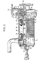
- Fig. 2 there is illustrated another embodiment of the canned motor pump for use in the high temperature according to the invention.
- a liner disc 58 arranged between the pump 10 and the adapter 14 at their joining site is extended at its rotor shaft 24 side, which is fitted with the bearing support 50 for dividing the path 48 of the adapter 14 into two portions (48a, 48b), one of which (48a) is then communicated with a hole 60 located at the liner disc 58 on its periphery side opposing to the impeller 16.
- an. internal conduit 62 is formed axially through the rotor shaft 24 and is communicated with the rear rotor chamber 36 via a hole 66 passed through an end nut 64 fitted to the rear end of the rotor shaft 24 on one hand, while the internal conduit 62 is communicated, on the other hand, with the other path portion 48b of the adapter 14 via a hole 70 passed through a spacer 68 provided at the front end of the rotor shaft 24. The path portion 48b is then communicated with the pump 10 on its lower pressure side.
- the construction of this embodiment is identical to that of Fig. 1 except that the internal conduit is provided within the rotor shaft in lieu of the external conduit. The closer description, therefore, may be omitted for the same construction.
- an aliquot of the high temperature fluid sucked in the pump 10 is introduced into the front rotor chamber 34 through the hole 60, the path portion 48a and the hole 52 in order. Then, the aliquot of the treating fluid introduced into the front rotor chamber 34 is circulated to the pump 10 on its lower pressure side sequentially through the holes 54, the path portion 48b and the balance hole 56 of the impeller 16 in order to lubricate the front bearing 30.
- a majority of the treating fluid introduced into the front rotor chamber 34 flows through the gap 46 between the rotor and the stator and then is guided to the rear rotor chamber 36 in order to absorb the generated heat of the motor for cooling.
- the embodiment as shown in Fig. 2 has advantages in that the heat dissipation from the high temperature fluid may be prevented, that the effective heat absorption or cooling may be achieved and that the construction may be convenient owing to unnecessity of arranging the external conduit when the. canned motor pump is used for the high temperature fluid with possible temperature decrease or for the treating fluid of a lower range of high temperature.
- a further embodiment of the canned motor pump for use in the high temperature wherein an auxiliary pump chamber 72 is defined between the front rotor chamber 34 and the adapter 14 at their joining site. Within the auxiliary pump chamber 72 is arranged an auxiliary impeller 74, which is secured to the rotor shaft 24.
- the adapter 14 is provided with the path 48, as in the embodiment shown in Fig. 1, one end of which is communicated with the back side of the impeller 16 in the pump chamber 18 and the other end is communicated with the back side of the auxiliary impeller 74 in the auxiliary pump chamber 72. Further, a part of the adapter 14 is provided with a path 76 communicating the auxiliary pump chamber 72 on its delivery side, while an external conduit 78 is arranged for communicating the path 76 with the rear rotor chamber 36. The external conduit 78 may be provided with a cooling fin 80, if desired. Otherwise the construction of this embodiment is identical to that of Fig. 1. The close description, therefore, may be omitted for the same construction.
- an aliquot of the high temperature fluid to be treated is introduced into the auxiliary pump chamber 72 via the path 48 from the back side of the impeller 16 and then is guided to the rear rotor chamber 36 through the external conduit 78 under action of the auxiliary impeller 74, wherein the high temperature fluid is cooled by the ambient atmosphere in the external conduit 78.
- the treating fluid thus cooled may absorb the generated heat from the motor upon flowing through the canned motor 12 on one hand and lubricate the front and rear bearings on the other hand.
- the treating fluid introduced into the front rotor chamber 34 is then forcibly circulated to the external conduit 78 under action of the auxiliary impeller 74, thereby repeating the operation as described hereiribefore.
- a deficient or excess amount of the treating fluid circulated through the canned motor 12 may be adjusted by the treating fluid of the pump 10 through the path 48 of the adapter 14. Therefore, an aliquot of the high temperature fluid may be circulated through the canned motor under natural cooling, as in the embodiment in Fig. 1, thereby absorbing all of the generated heat of the motor.
- the pumping of the high temperature fluid may be conveniently and economically effected.
- the canned motor pump according to the invention when used for treating the high temperature fluid of more than 200°C, permits the canned motor to be operated with sufficient dielectric strength and also to be cooled and lubricated under natural cooling of the high temperature fluid, thereby providing the excellent and economical canned motor pump contributing to the saving in the natural resource and energy without arranging a particular cooling means.
- the canned motor pump according to the invention may employ the treating fluid of relatively high temperature to absorb the generated heat from the motor for cooling, thereby allowing not only the means of less energy-loss to be employed but also the heat load of the heating source (for example, a fuel cost for a boiler or a heater) to be alleviated in a plant for manufacturing the high temperature liquid.
- the heating source for example, a fuel cost for a boiler or a heater
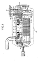
- the whole circumference of the canned motor 12 as well as portions of the pump 10 and the adapter 14 connected to the canned motor 12 are closely surrounded by a thermal insulating material 82, which may completely prevent the generated heat of the canned motor 12 from being dissipated.
- a thermal insulating material 82 which may completely prevent the generated heat of the canned motor 12 from being dissipated.
- all of the generated heat may be absorbed, as in the embodiment shown in Fig. 2, into the treating fluid circulating through the canned motor 12.
- the canned motor pump as shown in Fig. 4 if employed as a feeding pump in the manufacturing plant for the high temperature fluid, permits all of the generated heat of the motor to be absorbed in the treating fluid, thereby reducing the energy loss and alleviating the heat load of the heating source (for example, the fuel cost for the boiier orthe heater).
Description
- This invention relates to a canned motor pump transporting a high temperature fluid or liquid, more particularly to a canned motor pump for use at a high temperature in which the generated heat from the motor can be absorbed in a treating fluid upon circulation through the canned motor at the high temperature for maintaining optimum operation of the motor, thereby permitting the heat load of a heating source to be alleviated when used in a plant for manufacturing the high temperature liquid.
- In general, the canned motor pump is cooled at its motor part and lubricated at its bearing by circulating an aliquot of the treating fluid through
- a rotor chamber of the canned motor (US-A-3 306 222). In the canned motor pump for treating the fluid of more than 200°C, however, the motor is difficult to be cooled directly by the treating fluid, necessitating a cooling system, for example, with a cooling water or others. For this reason, such type of canned motor has a disadvantage of a high initial cost for additional arrangement of a cooling water system other than the pumping system. Further, the conventional canned motor pump is unsatisfactory in saving of a natural resource or energy, because of a higher heat loss caused by cooling and of an extremely high fuel cost of the heating source for the high temperature fluid.
- Although the improvement in the heat resistance of motor components is necessary for enhancing that of the canned motor itself, the dielectric strength of the winding in the high temperature is especially important. The conventional canned motor of a general structure has an insulation for insulating a set of windings, which is thermally deteriorated in the high temperature atmosphere of more than 200°C, leading to a poor mechanical strength and disruption of the windings (US-A-3 688 137).
- A general object of the invention is to provide an economically superior canned motor pump for use at a high temperature, in which the heat resistance of the canned motor is improved, the heat value generated from the canned motor is absorbed in the treating fluid through a simple construction, the heat load for the heating source in the manufacturing plant of the high temperature fluid is alleviated, and the saving of the natural resource and energy may be achieved.
- A principal object of the invention is to provide a canned motor pump for use in the high temperature, for treating a fluid of more than 200°C, which comprises a canned motor improved in dielectric strength for the high temperature by impregnating its field winding with an insulating material of special silicone resin and subsequently curing.
- To this end, the present invention as defined in the first part of claim 1 is characterized in that said silicone resin is filled with fluorinated mica.
- In this respect it has further been found that the mechanical and the dielectric strength of the winding may be increased by using as the insulation for the winding an insulation formed in such a way that synthetic fluorinated mica pieces are suspended in an organic silicone compound solvent and the resulting material is impregnated and cured.
- If such type of insulating is used, some fluorine compounds from the synthetic fluorinated mica may vaporize in the high temperature atmosphere of more than 200°C, which compounds may melt siloxane from the organic silicone compound for ceramicization, thereby increasing the mechanical and dielectric strength of the winding.
- Furthermore, the field winding may preferably be formed by use of a winding made from a nickel-plated copper wire coated thereon with a glass insulating coat, a wedge made from laminated mica bonded with an inorganic material, a flexible insulating sheet made from laminated mica using a possibly least amount of special silicone resin adhesive, and an impregnating material for insulation of special silicone resin filled with synthetic fluorinated mica. In this case, the impregnating material may be a suspension of synthetic fluorinated mica pieces in an organic silicone compound solvent.
- The canned motor pump according to the invention may further comprise an thermal insulation sealingly surrounding the whole periphery of the canned motor, the generated heat from which is absorbed in the treating fluid, thereby allowing the canned motor pump to be used as a pump for feeding the high temperature fluid and alleviating the heat load for the heating source.
- The invention will now be described in more detail by the non-limiting embodiments with reference to the accompanying drawings.
- One way of carrying out the invention is described in detail below with reference to drawing which illustrate preferred embodiments, in which:-
- Figure 1 is a sectional side view of a main portion of the canned motor pump for use in the high temperature according to one embodiment of the invention,
- Figure 2 is a sectional side view of a main portion of the canned motor pump according to another embodiment of the invention,
- Figure 3 is a sectional side view of a main portion of the canned motor pump according to a further embodiment of the invention, and
- Figure 4 is a sectional side view of a main portion of the canned motor pump according to a still further embodiment of the invention.
- In Figure 1 there is illustrated the canned motor pump for use in the high temperature according to the invention comprising a
pump 10 and a cannedmotor 12, wherein thepump 10 and themotor 12 are interchangeably connected with anadapter 14. - The
pump 10 is provided with asuction pipe 20 and adelivery pipe 22, each communicating with apump chamber 18 having therein animpeller 16 which is secured to an extended end of arotor shaft 24 for themotor 12. Themotor 12 comprises astator assembly 26 and arotor assembly 28. Therotor shaft 24 is supported by a front and a rear bearing 30 and 32, respectively. At the either ends of therotor assembly 28 are formed afront rotor chamber 34 and arear rotor chamber 36, respectively. To therear rotor chamber 36 at its rear end is communicated anexternal conduit 38 derived from thedelivery pipe 22 of thepump 10. Thus, an aliquot of the treating fluid is introduced into therear rotor chamber 36 through thedelivery pipe 22 of thepump 10 and is passed throughholes 40 provided on an inner circumference of arear bearing 32 and throughholes 44 provided in abearing support 42 securing therear bearing 32 in order to lubricate the latter and to absorb the generated heat from the motor. The treating fluid introduced into therear rotor chamber 36 is transported to thefront rotor chamber 34 through agap 46 between the rotor and the stator. - The
adapter 14 is provided with a flowingpath 48 for communicating thefront rotor chamber 34 with thepump 10 on its lower pressure side. In other words, the flowingpath 48 is communicated with thefront rotor chamber 34 throughholes 52 provided in abearing support 50 securing a front bearing 30 and throughholes 54 provided on an inner circumference of the front bearing 30 in order to introduce the treating fluid, which has completed the lubrication of the front bearing 30 and the absorption of the generated heat from the motor, into the flowingpath 48. The treating fluid introduced into the flowingpath 48 is then guided to theimpeller 16 on its suction port side via abalance hole 56 which is passed through theimpeller 16 from its back side. - For the canned motor used in the invention, a field winding is improved in its insulating treatment in order to enhance the heat resistance or the dielectric strength for the high temperature in comparison with the conventional canned motor. A copper wire employed as a winding conductor is plated with nickel thereon and is additionally coated with a glass insulating coat for protection from thermal oxidation. Further, a laminated mica plate bonded with an inorganic material is used for a wedge, while laminated mica with a possibly least amount of a special silicone resin adhesive is utilized for a flexible insulating sheet. As an impregnating material for insulating the windings from each other and an embedding material for coil ends, there is used a suspension of synthetic fluorinated mica pieces in an organic silicone compound solvent. In this case, the synthetic fluorinated mica pieces having the thickness below 5 nm and the diameter of 0.1 to 5 Ilm are used together with the organic solvent, such as a solvent mixture of sylene, butylcellosolve and cellosolve acetate, in a weight ratio of the mica to the solvent of 1:1 or more. The resulting suspension is then impregnated and cured onto the winding.
- If the field winding is treated for insulation in this way, some fluorine compounds, such as SiF4, KF and others, from the synthetic fluorinated mica may vaporize and melt siloxane from the organic silicone compound for ceramicization in the high temperature of more than 200°C, thereby improving the mechanical strength and dielectric strength of the winding. Thus, the canned motor may be imparted with sufficient dielectric strength to endure the high temperature atmosphere of more than 300°C, thereby permitting the canned motor to be satisfactorily operated in the canned motor pump.
- In accordance with the embodiment as shown in Fig. 1, the treating fluid of high temperature discharged from the
pump 10 is cooled by the ambient atmosphere when introduced into therear rotor chamber 36 through theexternal conduit 38. The treating fluid thus cooled absorbs the heat generated from the motor upon flowing through the cannedmotor 12 for substantially cooling the motor and lubricating the front andrear bearings pump 10 on its lower pressure side through thepath 48 of theadapter 14. - As apparent from the foregoing, the canned motor pump of this embodiment may introduce an aliquot of the high temperature fluid into the canned motor under natural cooling and allow all of the generated heat of the motor to be absorbed by the treating fluid which is then circulated to the pump, thereby achieving the effective utilization of the heat energy. Thus, pumping of the high temperature fluid, which has hitherto been considered difficult, may be conveniently and economically achieved. When the temperature of the treating fluid increases, the
external conduit 38 is preferably provided with a cooling fin, if necessary. - In Fig. 2 there is illustrated another embodiment of the canned motor pump for use in the high temperature according to the invention. In this embodiment, a
liner disc 58 arranged between thepump 10 and theadapter 14 at their joining site is extended at itsrotor shaft 24 side, which is fitted with thebearing support 50 for dividing thepath 48 of theadapter 14 into two portions (48a, 48b), one of which (48a) is then communicated with ahole 60 located at theliner disc 58 on its periphery side opposing to theimpeller 16. - Further, an.
internal conduit 62 is formed axially through therotor shaft 24 and is communicated with therear rotor chamber 36 via ahole 66 passed through anend nut 64 fitted to the rear end of therotor shaft 24 on one hand, while theinternal conduit 62 is communicated, on the other hand, with theother path portion 48b of theadapter 14 via ahole 70 passed through aspacer 68 provided at the front end of therotor shaft 24. Thepath portion 48b is then communicated with thepump 10 on its lower pressure side. The construction of this embodiment is identical to that of Fig. 1 except that the internal conduit is provided within the rotor shaft in lieu of the external conduit. The closer description, therefore, may be omitted for the same construction. - In the embodiment of the canned motor pump as shown in Fig. 2 an aliquot of the high temperature fluid sucked in the
pump 10 is introduced into thefront rotor chamber 34 through thehole 60, thepath portion 48a and thehole 52 in order. Then, the aliquot of the treating fluid introduced into thefront rotor chamber 34 is circulated to thepump 10 on its lower pressure side sequentially through theholes 54, thepath portion 48b and thebalance hole 56 of theimpeller 16 in order to lubricate the front bearing 30. A majority of the treating fluid introduced into thefront rotor chamber 34, on the other hand, flows through thegap 46 between the rotor and the stator and then is guided to therear rotor chamber 36 in order to absorb the generated heat of the motor for cooling. An aliquot of the treating fluid introduced into therear rotor chamber 36 is circulated to theholes 40 for lubricating therear bearing 32. Then, a majority of the treating fluid introduced into therear rotor chamber 36 is circulated to thepump 10 on its lower pressure side sequentially through thehole 44 of thebearing support 42, thehole 66 of theend nut 64, theinternal conduit 62 of therotor shaft 24, thehole 70 of thespacer 68, thepath 48b and thebalance hole 56 of theimpeller 16. Thus, the embodiment as shown in Fig. 2 has advantages in that the heat dissipation from the high temperature fluid may be prevented, that the effective heat absorption or cooling may be achieved and that the construction may be convenient owing to unnecessity of arranging the external conduit when the. canned motor pump is used for the high temperature fluid with possible temperature decrease or for the treating fluid of a lower range of high temperature. - In Fig. 3, there is illustrated a further embodiment of the canned motor pump for use in the high temperature according to the invention, wherein an
auxiliary pump chamber 72 is defined between thefront rotor chamber 34 and theadapter 14 at their joining site. Within theauxiliary pump chamber 72 is arranged an auxiliary impeller 74, which is secured to therotor shaft 24. - The
adapter 14 is provided with thepath 48, as in the embodiment shown in Fig. 1, one end of which is communicated with the back side of theimpeller 16 in thepump chamber 18 and the other end is communicated with the back side of the auxiliary impeller 74 in theauxiliary pump chamber 72. Further, a part of theadapter 14 is provided with apath 76 communicating theauxiliary pump chamber 72 on its delivery side, while anexternal conduit 78 is arranged for communicating thepath 76 with therear rotor chamber 36. Theexternal conduit 78 may be provided with a coolingfin 80, if desired. Otherwise the construction of this embodiment is identical to that of Fig. 1. The close description, therefore, may be omitted for the same construction. - In accordance with the canned motor pump as shown in Fig. 3, an aliquot of the high temperature fluid to be treated is introduced into the
auxiliary pump chamber 72 via thepath 48 from the back side of theimpeller 16 and then is guided to therear rotor chamber 36 through theexternal conduit 78 under action of the auxiliary impeller 74, wherein the high temperature fluid is cooled by the ambient atmosphere in theexternal conduit 78. The treating fluid thus cooled may absorb the generated heat from the motor upon flowing through the cannedmotor 12 on one hand and lubricate the front and rear bearings on the other hand. The treating fluid introduced into thefront rotor chamber 34 is then forcibly circulated to theexternal conduit 78 under action of the auxiliary impeller 74, thereby repeating the operation as described hereiribefore. Thus, in accordance with the canned motor pump as shown in Fig. 3, a deficient or excess amount of the treating fluid circulated through the cannedmotor 12 may be adjusted by the treating fluid of thepump 10 through thepath 48 of theadapter 14. Therefore, an aliquot of the high temperature fluid may be circulated through the canned motor under natural cooling, as in the embodiment in Fig. 1, thereby absorbing all of the generated heat of the motor. Thus, the pumping of the high temperature fluid may be conveniently and economically effected. - As apparent from the various embodiments described hereinbefore, the canned motor pump according to the invention, when used for treating the high temperature fluid of more than 200°C, permits the canned motor to be operated with sufficient dielectric strength and also to be cooled and lubricated under natural cooling of the high temperature fluid, thereby providing the excellent and economical canned motor pump contributing to the saving in the natural resource and energy without arranging a particular cooling means.
- In addition, the canned motor pump according to the invention, owing to its improved dielectric strength of the canned motor, may employ the treating fluid of relatively high temperature to absorb the generated heat from the motor for cooling, thereby allowing not only the means of less energy-loss to be employed but also the heat load of the heating source (for example, a fuel cost for a boiler or a heater) to be alleviated in a plant for manufacturing the high temperature liquid.
- As shown in Fig. 4, for example, the whole circumference of the canned
motor 12 as well as portions of thepump 10 and theadapter 14 connected to the cannedmotor 12 are closely surrounded by a thermal insulatingmaterial 82, which may completely prevent the generated heat of the cannedmotor 12 from being dissipated. Thus, all of the generated heat may be absorbed, as in the embodiment shown in Fig. 2, into the treating fluid circulating through the cannedmotor 12. In this way, the canned motor pump as shown in Fig. 4, if employed as a feeding pump in the manufacturing plant for the high temperature fluid, permits all of the generated heat of the motor to be absorbed in the treating fluid, thereby reducing the energy loss and alleviating the heat load of the heating source (for example, the fuel cost for the boiier orthe heater).
Claims (3)
Applications Claiming Priority (2)
| Application Number | Priority Date | Filing Date | Title |
|---|---|---|---|
| JP3780/81 | 1981-01-16 | ||
| JP378081A JPS57119194A (en) | 1981-01-16 | 1981-01-16 | Canned motor pump for use at high temperature |
Publications (3)
| Publication Number | Publication Date |
|---|---|
| EP0056440A1 EP0056440A1 (en) | 1982-07-28 |
| EP0056440B1 true EP0056440B1 (en) | 1985-04-10 |
| EP0056440B2 EP0056440B2 (en) | 1990-08-22 |
Family
ID=11566694
Family Applications (1)
| Application Number | Title | Priority Date | Filing Date |
|---|---|---|---|
| EP19810108865 Expired EP0056440B2 (en) | 1981-01-16 | 1981-10-24 | A canned motor pump for use in the high temperature |
Country Status (4)
| Country | Link |
|---|---|
| EP (1) | EP0056440B2 (en) |
| JP (1) | JPS57119194A (en) |
| DE (1) | DE3169870D1 (en) |
| MX (1) | MX153672A (en) |
Families Citing this family (2)
| Publication number | Priority date | Publication date | Assignee | Title |
|---|---|---|---|---|
| JPS5958197A (en) * | 1982-09-28 | 1984-04-03 | Nikkiso Co Ltd | Canned motor pump |
| EP0844723A3 (en) * | 1996-11-25 | 1999-05-06 | ATB Austria Antriebstechnik Aktiengesellschaft | Electric motor driven pump |
Family Cites Families (9)
| Publication number | Priority date | Publication date | Assignee | Title |
|---|---|---|---|---|
| GB701511A (en) * | 1949-11-01 | 1953-12-30 | Hayward Tyler & Co Ltd | Improvements in and relating to pump and motor combinations |
| CH346109A (en) * | 1954-10-29 | 1960-04-30 | Gen Electric | Submersible unit consisting of an electric motor and centrifugal pump |
| GB906306A (en) * | 1960-01-25 | 1962-09-19 | Hayward Tyler & Company Ltd | Improvements in or relating to pump and motor combinations |
| BE644859A (en) * | 1963-03-06 | |||
| US3483413A (en) * | 1964-06-03 | 1969-12-09 | Gen Motors Corp | Armature winding end turn banding and slot insulators |
| GB1043468A (en) * | 1964-06-25 | 1966-09-21 | Beresford James & Son Ltd | Electrically driven circulating pump |
| FR1422113A (en) * | 1964-09-09 | 1965-12-24 | Commissariat Energie Atomique | Improvements made to electromotive groups, especially electropumps |
| US3347168A (en) * | 1966-02-16 | 1967-10-17 | Westinghouse Electric Corp | Motor pump unit |
| FR2087126A5 (en) * | 1970-05-05 | 1971-12-31 | Brissonneau & Lotz |
-
1981
- 1981-01-16 JP JP378081A patent/JPS57119194A/en active Granted
- 1981-10-24 DE DE8181108865T patent/DE3169870D1/en not_active Expired
- 1981-10-24 EP EP19810108865 patent/EP0056440B2/en not_active Expired
- 1981-11-13 MX MX19009781A patent/MX153672A/en unknown
Also Published As
| Publication number | Publication date |
|---|---|
| DE3169870D1 (en) | 1985-05-15 |
| JPH0130382B2 (en) | 1989-06-19 |
| JPS57119194A (en) | 1982-07-24 |
| EP0056440A1 (en) | 1982-07-28 |
| EP0056440B2 (en) | 1990-08-22 |
| MX153672A (en) | 1986-12-16 |
Similar Documents
| Publication | Publication Date | Title |
|---|---|---|
| CA1177328A (en) | Canned motor pump for use in the high temperature | |
| US4808087A (en) | Canned motor pump | |
| US7816824B2 (en) | Electric motor with permanent magnet excitation and rotor cooling | |
| US5122704A (en) | Composite rotor sleeve | |
| US8215928B2 (en) | Foil gas bearing supported high temperature centrifugal blower and method for cooling thereof | |
| US4295067A (en) | Cooling apparatus for electrical machinery | |
| EP0874444A1 (en) | Heat conducting means for electric motor or generator | |
| EP0463084B1 (en) | An improved cooling system for generators | |
| US8129875B2 (en) | Motor cooling structure | |
| US11901775B2 (en) | Rotor, motor, and electric vehicle | |
| US3445695A (en) | Cooling system for hermetic dynamoelectric devices | |
| US3995181A (en) | Matrix for enhancing the flow of coolant through an alternator stator | |
| US20030173840A1 (en) | Assembly and method for direct cooling of motor end-winding | |
| US2706260A (en) | Liquid cooled dynamo-electric machine | |
| EP0056440B1 (en) | A canned motor pump for use in the high temperature | |
| CN102097907B (en) | Sealing device and condensing unit of evaporative cooling asynchronous motor stator as well as manufacturing methods thereof | |
| JPH0591696A (en) | Rotating machine | |
| US3075107A (en) | Canned motor | |
| CN111245147B (en) | Mixed cooling system of birotor stator yoke-free modular axial motor | |
| KR20200007293A (en) | Electric motor | |
| JPH0445679B2 (en) | ||
| US3238400A (en) | Gas input assisted evacuation of rotor-stator gaps | |
| US3294991A (en) | Induced vaporization cooling of rotary electrical machines | |
| CN208424048U (en) | The motor of high power density | |
| JPH0130383B2 (en) |
Legal Events
| Date | Code | Title | Description |
|---|---|---|---|
| PUAI | Public reference made under article 153(3) epc to a published international application that has entered the european phase |
Free format text: ORIGINAL CODE: 0009012 |
|
| AK | Designated contracting states |
Designated state(s): CH DE FR GB IT NL SE |
|
| 17P | Request for examination filed |
Effective date: 19821230 |
|
| ITF | It: translation for a ep patent filed |
Owner name: FUMERO BREVETTI S.N.C. |
|
| GRAA | (expected) grant |
Free format text: ORIGINAL CODE: 0009210 |
|
| AK | Designated contracting states |
Designated state(s): CH DE FR GB IT LI NL SE |
|
| REF | Corresponds to: |
Ref document number: 3169870 Country of ref document: DE Date of ref document: 19850515 |
|
| ET | Fr: translation filed | ||
| PLBI | Opposition filed |
Free format text: ORIGINAL CODE: 0009260 |
|
| 26 | Opposition filed |
Opponent name: KLEIN, SCHANZLIN & BECKER AG Effective date: 19860109 |
|
| NLR1 | Nl: opposition has been filed with the epo |
Opponent name: KLEIN, SCHANZLIN & BECKER AG |
|
| PLAB | Opposition data, opponent's data or that of the opponent's representative modified |
Free format text: ORIGINAL CODE: 0009299OPPO |
|
| R26 | Opposition filed (corrected) |
Opponent name: KSB AKTIENGESELLSCHAFT Effective date: 19860109 |
|
| NLXE | Nl: other communications concerning ep-patents (part 3 heading xe) |
Free format text: IN PAT.BUL.06/86,PAGE 701:CORR.:KSB AKTIENGESELLSCHAFT |
|
| PUAH | Patent maintained in amended form |
Free format text: ORIGINAL CODE: 0009272 |
|
| STAA | Information on the status of an ep patent application or granted ep patent |
Free format text: STATUS: PATENT MAINTAINED AS AMENDED |
|
| 27A | Patent maintained in amended form |
Effective date: 19900822 |
|
| AK | Designated contracting states |
Kind code of ref document: B2 Designated state(s): CH DE FR GB IT NL SE |
|
| NLR2 | Nl: decision of opposition | ||
| ITF | It: translation for a ep patent filed |
Owner name: FUMERO BREVETTI S.N.C. |
|
| ET3 | Fr: translation filed ** decision concerning opposition | ||
| ET3 | Fr: translation filed ** decision concerning opposition | ||
| NLR3 | Nl: receipt of modified translations in the netherlands language after an opposition procedure | ||
| ITTA | It: last paid annual fee | ||
| EAL | Se: european patent in force in sweden |
Ref document number: 81108865.7 |
|
| PGFP | Annual fee paid to national office [announced via postgrant information from national office to epo] |
Ref country code: SE Payment date: 20000906 Year of fee payment: 20 Ref country code: FR Payment date: 20000906 Year of fee payment: 20 |
|
| PGFP | Annual fee paid to national office [announced via postgrant information from national office to epo] |
Ref country code: GB Payment date: 20001013 Year of fee payment: 20 |
|
| PGFP | Annual fee paid to national office [announced via postgrant information from national office to epo] |
Ref country code: DE Payment date: 20001030 Year of fee payment: 20 |
|
| PGFP | Annual fee paid to national office [announced via postgrant information from national office to epo] |
Ref country code: NL Payment date: 20001031 Year of fee payment: 20 |
|
| PGFP | Annual fee paid to national office [announced via postgrant information from national office to epo] |
Ref country code: CH Payment date: 20001101 Year of fee payment: 20 |
|
| PG25 | Lapsed in a contracting state [announced via postgrant information from national office to epo] |
Ref country code: LI Free format text: LAPSE BECAUSE OF EXPIRATION OF PROTECTION Effective date: 20011023 Ref country code: GB Free format text: LAPSE BECAUSE OF EXPIRATION OF PROTECTION Effective date: 20011023 Ref country code: CH Free format text: LAPSE BECAUSE OF EXPIRATION OF PROTECTION Effective date: 20011023 |
|
| PG25 | Lapsed in a contracting state [announced via postgrant information from national office to epo] |
Ref country code: NL Free format text: LAPSE BECAUSE OF EXPIRATION OF PROTECTION Effective date: 20011024 |
|
| PG25 | Lapsed in a contracting state [announced via postgrant information from national office to epo] |
Ref country code: SE Free format text: THE PATENT HAS BEEN ANNULLED BY A DECISION OF A NATIONAL AUTHORITY Effective date: 20011030 |
|
| REG | Reference to a national code |
Ref country code: GB Ref legal event code: PE20 Effective date: 20011023 |
|
| REG | Reference to a national code |
Ref country code: CH Ref legal event code: PL |
|
| EUG | Se: european patent has lapsed |
Ref document number: 81108865.7 |
|
| NLV7 | Nl: ceased due to reaching the maximum lifetime of a patent |
Effective date: 20011024 |