EP0056422A1 - Process and falsework for constructing bridges of reinforced concrete - Google Patents
Process and falsework for constructing bridges of reinforced concrete Download PDFInfo
- Publication number
- EP0056422A1 EP0056422A1 EP81100282A EP81100282A EP0056422A1 EP 0056422 A1 EP0056422 A1 EP 0056422A1 EP 81100282 A EP81100282 A EP 81100282A EP 81100282 A EP81100282 A EP 81100282A EP 0056422 A1 EP0056422 A1 EP 0056422A1
- Authority
- EP
- European Patent Office
- Prior art keywords
- section
- bridge
- formwork
- scaffold
- supports
- Prior art date
- Legal status (The legal status is an assumption and is not a legal conclusion. Google has not performed a legal analysis and makes no representation as to the accuracy of the status listed.)
- Withdrawn
Links
Images


Classifications
-
- E—FIXED CONSTRUCTIONS
- E01—CONSTRUCTION OF ROADS, RAILWAYS, OR BRIDGES
- E01D—CONSTRUCTION OF BRIDGES, ELEVATED ROADWAYS OR VIADUCTS; ASSEMBLY OF BRIDGES
- E01D21/00—Methods or apparatus specially adapted for erecting or assembling bridges
- E01D21/10—Cantilevered erection
-
- E—FIXED CONSTRUCTIONS
- E01—CONSTRUCTION OF ROADS, RAILWAYS, OR BRIDGES
- E01D—CONSTRUCTION OF BRIDGES, ELEVATED ROADWAYS OR VIADUCTS; ASSEMBLY OF BRIDGES
- E01D2101/00—Material constitution of bridges
- E01D2101/20—Concrete, stone or stone-like material
- E01D2101/24—Concrete
- E01D2101/26—Concrete reinforced
- E01D2101/28—Concrete reinforced prestressed
Definitions
- the invention relates to a method of the type specified in the preamble of claim 1.
- Such a method is the subject of European patent application 80100241.1.
- This method enables an economical bridge construction in the cycle method for all applications in which the bridge height is relatively low, e.g. also in the production of highways. Since the concreting takes place in in-situ concrete, a displacement of the bridge sections is avoided, which was necessary with other known cycle shifting methods (cf. DE-PS 12 37 603).
- the clock-type scaffolding used for this is fed step by step on a moving sliding track, which is always created at a low height above the ground, regardless of uneven terrain, at the same distance from the lower edge of the bridge structure.
- the auxiliary foundations only required during construction cannot always be dimensioned according to the main foundations, e.g. due to deep foundations, so that settlement-free support cannot be guaranteed for these auxiliary foundations.
- the process of concreting can be controlled in such a way that a sufficient delay in the hardening of the concrete and selection of the direction of concreting elapses a long time before the concreting process is completed, and during this time height corrections can be carried out in a plastic concrete condition.
- bias This period is generally two to three days. If unnoticed subsidence occurs during this time, additional stress can be applied to the non-prestressed concrete. This additional stress does not generally lead to the complete failure of the supporting force of the cycle shifting frame, since spring-back forces from the main beam deflection also result in upward supporting forces in this case. However, this only applies to a certain degree of settlement.
- the supporting forces from the scaffolding are reduced or redistributed in any case, and there are corresponding cutting forces in the still fresh, non-prestressed concrete.
- the extent to which these cutting forces can be absorbed by sagging probation varies from case to case.
- the invention is therefore based on the object of designing the method according to the preamble of claim 1 in such a way that the loads transferred from the teaching scaffold to the auxiliary foundations become lower or are set down at supporting points which can be controlled at a lower and better height.
- This suspension of the scaffolding on the already concrete last section of the bridge ensures that about half the concrete load and the scaffold structure over the Bridge section is transferred to the main pillar or an auxiliary support, and the scaffold supports accordingly only need to absorb about half the load. It is expedient to retract, swing out or dismantle the supports adjacent to this suspension point in order to make only the supports located in the forward direction of the load bearing effective.
- the suspension can either be articulated only to absorb transverse forces, or it can be anchored in such a way that transverse forces and bending moments can be absorbed.
- the rear support in the direction of travel can be folded up, removed or retracted.
- the invention makes it possible to use larger spans for the main scaffold girders if they are dimensioned accordingly.
- the main framework girders In the connection area to the previously concreted sections, the main framework girders only bend during concreting, but no longer in the first solidification period before prestressing.
- the front scaffold column When the front scaffold column is set, there are only slight additional stresses in any case, since the static system for this settlement load case is usually an externally supported long cantilever beam, which is very insensitive to lowering this support. In any case, no cracks will occur in the critical connection area on the section already concreted. If the outer scaffold support is subsequently set, additional pressure forces are created in the connection area on the underside of the cross-section, which is usually the most endangered cross-section point for cracks.
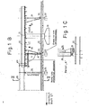
- FIG. 1A shows a part of a prestressed concrete bridge which is under construction and which, after completion, is supported on pillars 12 supported by main foundations 10 via bridge bearings 14.
- the bridge is sectionally reinforced and concreted in place using a formwork 17 carried by a scaffolding 16.
- the bridge superstructure consists of a pillar 12 resting concrete bridge sections 18 and intermediate Verbin d ungs bridge concrete sections 20. All portions which are concreted on the same formwork 17, are manufactured on einunddem sweater falsework.
- 10 auxiliary foundations 22 are erected in the ground between the main foundations, each of which has two foundation blocks 24, 26 according to the exemplary embodiments shown.
- Auxiliary supports 30 are supported on the foundation blocks 24, which support this section of the bridge superstructure after completion of a connecting section 20, as long as the connection to the bridge section 18 carried by the next bridge pier is not completed and sufficient prestressing has not yet been applied.
- the foundation blocks 26 carry a sliding track formed by rails 32, which is preferably created or built up by walking, ie only over a short length in front of and behind the cycle to be concreted.
- the scaffolding 16 can be moved on this sliding path.
- the rails 32 always run at the same distance from the lower edge of the bridge superstructure, which can be horizontal but also incline, or can have the same or different radii of curvature, in which case the formwork would have to be modified accordingly.
- the scaffolding 16 rests on hydraulic press rams 36, which are carried by roller carriages 38 and run on the rails 32 of the sliding track and opposite those supporting the formwork 17 Cross members 40 are stiffened.
- the formwork with its longitudinal beams 48 is suspended at the front end of the previously constructed bridge section 20 via anchoring means 60, so that the rear press rams 36 are relieved and can be drawn in, dismantled or folded down.
- the auxiliary supports 30 and the pillars 12 stand in the way of the free movement of the framework supporting the formwork. Special precautions must therefore be taken in the area of the auxiliary supports 30 and in the area of the pillars 12, so that the parts of the formwork or scaffolding in the cross section of the supports or the pillars are removed from the displacement path. This is done in order to ensure the overall cohesion of the scaffolding and the formwork, in sections, namely that the displacement-obstructing part between two cross members 40 is removed with these, thereby ensuring that the rigid structure by the cross members remaining in front and behind the pillar preserved.
- the construction of the bridge superstructure then takes place in sections at the point where the bridge section in question comes to rest after the completion of the bridge structure.
- the formwork in the area of the bridge supports 14 must be removed and the formwork is attached in such a way that the upper plate of the bridge bearing 14 forms part of the formwork and is aligned with the remaining part of the formwork.
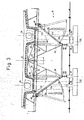
- FIG. 2 illustrate different possibilities of formwork and teaching scaffold structure for different pillar designs.
- there is only a single central support pillar 12 (which can optionally also be constructed in a resolved manner).
- the hydraulic press rams 36 can freely pass this central pillar 12 on the rails 32, and it is only necessary to ensure that the central part of the cross beams 40 and the formwork lying in the pillar area are removed.
- the cross members 40 are divided in this area into two sections 41 and 42, which are each displaceable in the direction of the arrow, the displacement can be done via spindles, hydraulic drives, rack jacks or the like ..
- the middle formwork plate 44 which lies in the area of the pillar 12, is divided in the longitudinal direction of the formwork in the longitudinal central axis and also has transverse divisions, so that the sections thus formed, as indicated by the arrows 45, can be folded down.
- the framework can be moved further by a field formed by the cross members 40, and the parts of the formwork plate 44 can then folded up again and the cross member sections 41, 42 are pushed inwards, so that again a rigid connection is ensured.
- This process is repeated step by step until the entire teaching scaffold has passed the pillar or until the scaffold has moved so far that the formwork with its center is above the pillar 12.
- auxiliary supports 30 which, as can be seen from FIG. 2, lie within the pillar cross section, so that when the formwork plate 44 is folded down, these supports can also be passed.
- the rear supports can also be easily dismantled, which is probably the simplest in practice.
- the inclined supports 50 for supporting the longitudinal beams 48 under the cantilever plates can remain firmly mounted during the entire displacement process.
- two pillars 12a and 12b are provided, along which the framework has to be moved.
- the inner foundation blocks 26 on which the running rails 32 are mounted, on which the hydraulic press rams 36 are supported or, in the retracted state, are moved over the roller carriages 38 etc.
- the auxiliary supports 30 are supported on the outer foundation block 24 and lie in the cross-sectional plane of the pillars 12a or 12b, so that it is possible to drive past both these auxiliary supports and the pillars when the corresponding parts lying in this cross section have been removed.
- the cross-member sections 41 and 42 are each displaced inward for the purpose of passing over the pillars in order to release the formwork panels 44 above the pillars 12a and 12b, which can be folded inward in the apparent manner 45.
- the scaffold inclined supports 50 which are pivoted outwards during the process, are supported on the base of the press rams 36.
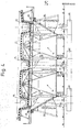
- three pillars 12c, 12d, 12e each have to be run over from the framework or the formwork.
- two frameworks 16 are provided, each running on two rails 32 of an outer or middle auxiliary foundation.
- the auxiliary supports 30 are again in the area of the cross section of the pillars and can therefore be avoided by the same precautions as the pillars themselves.
- the cross members 40 can also be displaced in sections and the corresponding formwork panels 46 are can be pivoted out of the cross-sectional area of the pillars or auxiliary supports.
- the cantilever structure is held together by longitudinal members 48, which extend over which are arranged above the cross beams 40 under the formwork 17 in a cross-sectional area which lies outside the cross-sectional area of the pillars.
- longitudinal beams 48 are connected to the hydraulic press rams 36, which in turn are stiffened in a suitable manner with one another and with the longitudinal and transverse beams.
- the cross members 40 are fixed and the sections 41 and 42 are slidably mounted.
- the scaffold For bridges according to Figure 3, which have two pillars per pillar transverse axis, the scaffold, as can be seen, consists of a central scaffold body, which rests on the rails 32, which are arranged on two separate foundations, and there are also two outer scaffold bodies which are provided by the uncouplable and inwardly displaceable cross beams are connected at a distance of one meter to three meters.
- Oblique supports 50 are articulated on the external masts and are supported on the respective roller carriages 38 via the feet of the press rams 36.
- the press rams 36 are therefore with the inclined supports 50 on the rail 32 above the foundation blocks 26.
- the hydraulic presses are retracted, so that the teaching frame is deposited on the roller carriages 38.
- the inclined supports 50 are temporarily pivoted away, so that in this state, the dead weight of the external structure is carried only by the projecting cross members 40 (in the extended state).
Abstract
Description
Die Erfindung bezieht sich auf ein Verfahren der im Oberbegriff des Patentanspruchs 1 angegebenen Gattung. Ein solches Verfahren ist Gegenstand der europäischen Patentanmeldung 80100241.1. Dieses Verfahren ermöglicht einen wirtschaftlichen Brückenaufbau im Taktverfahren für alle Anwendungsfälle, bei denen die Brückenhöhe relativ gering ist, z.B. auch bei der Herstellung von Hochstraßen. Da die Betonierung in Ortbeton erfolgt, wird eine Verschiebung der Brückenabschnitte vermieden, die bei anderen bekannten Taktschiebeverfahren erforderlich war (vgl. DE-PS 12 37 603). Der Vorschub des hierzu benutzten Takt-Lehrgerüstes erfolgt schrittweise auf einer mitwandernden Verschiebebahn, die unabhängig von Geländeunebenheiten in einer niedrigen Höhe über dem Erdreich stets im gleichen Abstand von der Unterkante des Brückenaufbaus erstellt wird.The invention relates to a method of the type specified in the preamble of claim 1. Such a method is the subject of European patent application 80100241.1. This method enables an economical bridge construction in the cycle method for all applications in which the bridge height is relatively low, e.g. also in the production of highways. Since the concreting takes place in in-situ concrete, a displacement of the bridge sections is avoided, which was necessary with other known cycle shifting methods (cf. DE-PS 12 37 603). The clock-type scaffolding used for this is fed step by step on a moving sliding track, which is always created at a low height above the ground, regardless of uneven terrain, at the same distance from the lower edge of the bridge structure.
Schwierigkeiten können bei Anwendung dieses bekannten Verfahrens dann entstehen, wenn die Gründung der Hilfsfundamente für die Verschiebebahn des Lehrgerüstes auf setzungsempfindlichen Boden erfolgen muß.Difficulties can arise when using this known method if the foundation of the auxiliary foundations for the trajectory of the scaffolding must take place on soil that is sensitive to settlement.
Aus Kostengründen können die nur während des Baus benötigten Hilfsfundamente nicht immer entsprechend den Hauptfundamenten bemessen werden, z.B. durch Tiefgründung, so daß für diese Hilfsfundamente eine setzungsfreie Abstützung nicht absolut gewährleistet werden kann.For cost reasons, the auxiliary foundations only required during construction cannot always be dimensioned according to the main foundations, e.g. due to deep foundations, so that settlement-free support cannot be guaranteed for these auxiliary foundations.
Um bei gleichem Kostenaufwand massivere Hilfsfundamente anwenden zu können, wäre es erwünscht, die Zahl der die Betonlast tragenden Hilfsfundamente zu verringern, was auch von Vorteil beim Überfahren von Verkehrswegen, Wasserläufen oder anderen Hindernissen sein würde.In order to be able to use more massive auxiliary foundations at the same cost, it would be desirable to reduce the number of auxiliary foundations carrying the concrete load, which would also be advantageous when driving over traffic routes, water courses or other obstacles.
Bisher hat man die Lage des Lehrgerüstes bei sich setzendem Boden dadurch aufrecht erhalten, daß das Absenken durch Anheben mittels hydraulischer Pressen ausgeglichen wurde. Es ist ferner durch die deutsche Patentanmeldung P 30 46 552.2 ein Hilfsstützenaufbau bekannt, der durch Umlenken von durch Gewichte eingeführte Stützkräfte einen Ausgleich von Fundamentsetzungen ermöglicht.So far, the position of the scaffolding with the floor settling has been maintained in that the lowering was compensated for by lifting by means of hydraulic presses. It is also known from the German
Der Vorgang des Betonierens läßt sich dabei so steuern, daß durch genügende Verzögerung der Betonerhärtung und Wahl der Betonierrichtung längere Zeit bis zum Abschluß des Betoniervorganges verstreicht und in dieser Zeit Höhenkorrekturen bei plastischem Betonzustand durchgeführt werden können. Es können sich jedoch gewisse Probleme vom Beginn der Erstarrung bis zur genügenden Erhärtung für eine Teilvorspannung ergeben. Dieser Zeitraum umfaßt im allgemeinen zwei bis drei Tage. Wenn in dieser Zeit unbemerkte Setzungen auftreten, kann eine Zusatzbeanspruchung auf den nicht vorgespannten Beton erfolgen. Diese Zusatzbeanspruchung führt zwar im allgemeinen nicht zum vollständigen Ausfall der Stützkraft des Taktverschiebegerüstes, da durch Rückfederungskräfte aus der Lehrgerüsthauptträgerdurchbiegung auch in diesem Fall nach oben gerichtete Abstützkräfte verbleiben. Jedoch gilt dies jeweils nur bis zu einem bestimmten Setzüngsmaß. Andererseits werden die Abstützkräfte aus dem Gerüst in jedem Fall reduziert bzw. umgelagert, und es ergeben sich entsprechend Schnittkräfte in dem noch frischen nicht vorgespannten Beton. Wieweit diese Schnittkräfte durch schlaffe Bewährung aufnehmbar sind, ist jeweils von Fall zu Fall verschieden.The process of concreting can be controlled in such a way that a sufficient delay in the hardening of the concrete and selection of the direction of concreting elapses a long time before the concreting process is completed, and during this time height corrections can be carried out in a plastic concrete condition. However, there can be certain problems from the start of solidification to sufficient hardening for a part result in bias. This period is generally two to three days. If unnoticed subsidence occurs during this time, additional stress can be applied to the non-prestressed concrete. This additional stress does not generally lead to the complete failure of the supporting force of the cycle shifting frame, since spring-back forces from the main beam deflection also result in upward supporting forces in this case. However, this only applies to a certain degree of settlement. On the other hand, the supporting forces from the scaffolding are reduced or redistributed in any case, and there are corresponding cutting forces in the still fresh, non-prestressed concrete. The extent to which these cutting forces can be absorbed by sagging probation varies from case to case.
Der Erfindung liegt daher die Aufgabe zugrunde, das Verfahren gemäß Oberbegriff des Anspruchs 1 so auszugestalten, daß die vom Lehrgerüst auf die Hilfsfundamente übertragene Belastungen geringer werden oder auf weniger und besser in ihrer Höhenlage zu kontrollierenden Abstützpunkte abgesetzt werden.The invention is therefore based on the object of designing the method according to the preamble of claim 1 in such a way that the loads transferred from the teaching scaffold to the auxiliary foundations become lower or are set down at supporting points which can be controlled at a lower and better height.
Gelöst wird die gestellte Aufgabe durch die im Kennzeichnungsteil des Anspruchs 1 angegebenen Merkmale. Durch diese Aufhängung des Lehrgerüstes am bereits betonierten letzten Brückenabschnitt wird gewährleistet, daß etwa die Hälfte der Betonlast und des Gerüstaufbaus über den Brückenabschnitt auf den Hauptpfeiler bzw. eine Hilfsstütze übertragen wird, und die Lehrgerüststützen demgemäß nur noch etwa die halbe Last aufzunehmen brauchen. Dabei ist es zweckmäßig, die Stützen benachbart zu diesem Aufhängepunkt einzuziehen, auszuschwenken oder zu demontieren, um nur die in Vorfahrrichtung vorn liegenden Stützen lasttragend wirksam zu machen. Die Aufhängung kann dabei entweder nur zur Aufnahme von Querkräften gelenkig ausgebildet sein, oder die Verankerung kann in der Weise erfolgen, daß Querkräfte und Biegemomente aufgenommen werden können. Dies geschieht zweckmäßigerweise durch Verlängerung der Hauptträger bis zum betonierten Abschnitt hin, und durch zusätzliche Konstruktionselemente, wobei der Anschluß an dem bereits vorher betonierten Abschnitt so dimensioniert werden muß, daß die anteilige Betonierlast und das Gerüsteigengewicht unter der Voraussetzung aufgenommen werden können, daß die innere Lehrgerüststütze nicht belastet wird. Die gesamte Last ruht dann auf dem vorher betonierten Abschnitt bzw. der äußeren Gerüststütze. Die hintere Gerüststütze wird daher nur zum Verfahren des Gerüstes benötigt.The problem is solved by the features specified in the characterizing part of claim 1. This suspension of the scaffolding on the already concrete last section of the bridge ensures that about half the concrete load and the scaffold structure over the Bridge section is transferred to the main pillar or an auxiliary support, and the scaffold supports accordingly only need to absorb about half the load. It is expedient to retract, swing out or dismantle the supports adjacent to this suspension point in order to make only the supports located in the forward direction of the load bearing effective. The suspension can either be articulated only to absorb transverse forces, or it can be anchored in such a way that transverse forces and bending moments can be absorbed. This is expediently done by extending the main girders up to the concreted section, and by additional structural elements, the connection to the previously concreted section having to be dimensioned in such a way that the proportionate concreting load and the weight of the scaffolding can be taken on the condition that the inner mast support is not charged. The entire load then rests on the previously concreted section or the outer scaffold support. The rear scaffold support is therefore only required to move the scaffold.
Für den Fall, daß die Anzahl der Stützen aus verkehrstechnischen Gründen reduziert werden soll, oder weil infolge der Geländeverhältnisse eine geringere Anzahl von Stützen vorteilhaft wäre, kann die jeweils in Fahrtrichtung hinten liegende Stütze hochklappbar,demontierbar oder einziehbar ausgeführt werden.In the event that the number of supports is to be reduced for traffic-related reasons, or because a smaller number of supports would be advantageous due to the terrain, the rear support in the direction of travel can be folded up, removed or retracted.
Durch die Erfindung wird es möglich, größere Stützweiten für die Lehrgerüsthauptträger zu benutzen, wenn diese entsprechend dimensioniert werden. Im Anschlußbereich an die vorher betonierten Abschnitte ergeben sich Durchbiegungen der Gerüsthauptträger nur während des Betonierens, jedoch nicht mehr in der ersten Erstarrungsperiode vor dem Vorspannen. Bei einer Setzung der vorderen Lehrgerüststütze ergeben sich in jedem Fall nur geringe Zusatzspannungen, da das statische System für diesen Setzungslastfall normalerweise ein außen abgestützter langer Kragbalken ist, der für Absenkung dieser Abstützung sehr unempfindlich ist. In dem kritischen Anschlußbereich an dem bereits betonierten Abschnitt werden jedenfalls keine Risse entstehen. Wenn die äußere Gerüststütze eine nachträgliche Setzung erfährt, entstehen im Anschlußbereich jedenfalls zusätzliche Druckkräfte an der Unterseite des Querschnitts, die zumeist die für Risse am meisten gefährdetste Querschnittsstelle ist.The invention makes it possible to use larger spans for the main scaffold girders if they are dimensioned accordingly. In the connection area to the previously concreted sections, the main framework girders only bend during concreting, but no longer in the first solidification period before prestressing. When the front scaffold column is set, there are only slight additional stresses in any case, since the static system for this settlement load case is usually an externally supported long cantilever beam, which is very insensitive to lowering this support. In any case, no cracks will occur in the critical connection area on the section already concreted. If the outer scaffold support is subsequently set, additional pressure forces are created in the connection area on the underside of the cross-section, which is usually the most endangered cross-section point for cracks.
Bei der Belastung des bereits betonierten und teilvorgespannten Abschnittes durch den Lehrgerüstaufbau für den nächsten Abschnitt ergeben sich Zusatzschnittkräfte, die aufgenommen werden müssen. Daher ist es erforderlich, die zentrische Vorspannung für diesen Lastfall zu dimensionieren und die Lage der zentrischen Vorspannung darauf abzustimmen. Im allgemeinen wird sich hierdurch eine Vergrößerung der zentrischen Vorspannung ergeben, die jedoch zumindest zu einer teilweisen Verringerung der nachträglich aufzubringenden exzentrischen Vorspannung führt. Die Aufwendungen für die Lehrgerüst-Hilfsfundamente werden demgegenüber geringer.When the already concreted and partially prestressed section is loaded by the framework structure for the next section, there are additional cutting forces that have to be absorbed. It is therefore necessary to dimension the central preload for this load case and to adapt the position of the central preload to it. In general, this will result in an increase in the central preload, which, however, leads at least to a partial reduction in the subsequently applied eccentric preload. In contrast, the expenses for the auxiliary scaffolding foundations are lower.
Da setzungsempfindliche Fundamente im Lehrgerüstbau um so besser zu beherrschen sind je weniger Stellen die Lasten tragen müssen, werden zweckmäßigerweise bei dem zur Durchführung des Verfahrens vorgesehenen Lehrgerüst nur die die Schienen abstützenden Fundamente benötigt, während die seitlichen Gerüstaufbauten über ausschwenkbare Schrägstützen getragen werden, die am Fuß der Hauptgerüststützen lösbar befestigt sind, so daß das Lehrgerüst dann im Normalfall nur noch an zwei Punkten aufliegt, falls an den vorher betonierten Abschnitt nach Fig. 1B angehängt wird, oder auf vier Punkten wenn die hinteren Stützen 36 tragend verbleiben.Since settling-sensitive foundations in teaching scaffolding are easier to control the fewer places the loads have to bear, it is advisable that only the foundations supporting the rails are required for the teaching scaffold provided for the implementation of the method, while the side scaffolding structures are supported by swiveling inclined supports that are attached to the foot the main scaffold supports are detachably fastened, so that the teaching scaffold then normally only rests at two points if it is attached to the previously concreted section according to FIG. 1B, or on four points if the rear supports 36 remain load-bearing.
Weitere Ausgestaltungen des erfindungsgemäßen Verfahrens ergeben sich aus den Ansprüchen 2 bis 5 und die Unteransprüche 6 bis 9 kennzeichnen weitere Ausgestaltungen des erfindungsgemäßen Lehrgerüstes.Further refinements of the method according to the invention result from claims 2 to 5 and subclaims 6 to 9 characterize further refinements of the teaching framework according to the invention.
Nachstehend werden Ausführungsbeispiele der Erfindung anhand der Zeichnung beschrieben. In der Zeichnung zeigenExemplary embodiments of the invention are described below with reference to the drawing. Show in the drawing
Figur 1A zusammen mit Figur 1B eine schematische Seitenansicht eines im Bau befindlichen Brückenbauwerks, das nach dem erfindungsgemäßen Taktverfahren abschnittsweise gemäß der zeichnerischen Darstellung von links nach rechts erstellt wird und
- Figur 1C eine Teilansicht der Presse zum Gerüstablassen, und
- Figur 2 einen Schnitt nach der Linie II-II gemäß Figur 1, welcher den zuletzt erstellten Brückenabschnitt mit seiner Schalung und einem diese Schalung tragenden Lehrgerüst erkennen läßt, mit einem Pfeiler pro Pfeilerachse und tragenden Mittelquerschnitt im Überbau, in größerem Maßstab und
- Figur 3 eine der Figur 2 entsprechende Schnittansicht einer Schalung mit Lehrgerüst bei einem Brückenaufbau mit zwei Pfeilern pro Pfeilerachse und
- Figur 4 eine den Figuren 2 und 3 entsprechende Schnittansicht einer Schalung mit Lehrgerüst für einen Brückenaufbau mit drei Pfeilern pro Pfeilerachse.
- Figure 1C is a partial view of the scaffold lowering press, and
- Figure 2 is a section along the line II-II of Figure 1, which shows the last created bridge section with its formwork and a scaffold supporting this formwork, with one pillar per pillar axis and supporting central cross-section in the superstructure, on a larger scale and
- Figure 3 is a sectional view corresponding to Figure 2 of a formwork with a scaffolding in a bridge structure with two pillars per pillar axis and
- Figure 4 is a sectional view corresponding to Figures 2 and 3 of a formwork with a scaffolding for a bridge structure with three pillars per pillar axis.
Figur 1A zeigt zusammen mit Figur 1B einen im Bau befindlichen Teil einer Spannbetonbrücke, die nach Fertigstellung auf von Hauptfundamenten 10 getragenen Pfeilern 12 über Brückenlager 14 abgestützt ist. Die Brücke wird abschnittsweise im Taktverfahren mittels einer von einem Lehrgerüst 16 getragenen Schalung 17 an Ort und Stelle armiert und betoniert. Gemäß dem dargestellten Ausführungsbeispiel besteht der Brückenoberbau aus auf einem Pfeiler 12 aufliegenden Brückenbetonabschnitten 18 und dazwischen befindlichen Verbindungs-Brückenbetonabschnitten 20. Sämtliche Abschnitte, die auf der gleichen Schalung 17 betoniert sind, werden auf einunddemselben Lehrgerüst gefertigt. Zum Aufbau der Brücke werden zwischen den Hauptfundamenten 10 Hilfsfundamente 22 im Boden erreichtet, die gemäß den dargestellten Ausführungsbeispielen jeweils zwei Fundamentblöcke 24, 26 aufweisen. Auf den Fundamentblöcken 24 sind Hilfsstützen 30 abgestützt, die nach Fertigstellung eines Verbindungsabschnittes 20 diesen Abschnitt des Brückenoberbaues tragen, solange die Verbindung mit dem vom nächsten Brückenpfeiler getragenen Brückenabschnitt 18 nicht vollendet ist und eine ausreichende Vorspannung noch nicht aufgebracht ist. Die Fundamentblöcke 26 tragen eine durch Schienen 32 gebildete Verschiebebahn, die vorzugsweise wandernd, d.h. nur auf eine kurze Länge vor und hinter dem zu betonierenden Takt erstellt bzw. aufgebaut wird. Auf dieser Verschiebebahn ist das Lehrgerüst 16 fahrbar. Die Schienen 32 verlaufen in einem stets gleichen Abstand von der Unterkante des Brückenoberbaues, der horizontal aber auch mit Gefälle verlaufend ausgebildet sein kann, oder auch gleiche oder unterschiedliche Krümmungsradien besitzen kann, in welch letzterem Falle die Schalung entsprechend abzuändern wäre.FIG. 1A, together with FIG. 1B, shows a part of a prestressed concrete bridge which is under construction and which, after completion, is supported on
Das Lehrgerüst 16 ruht auf hydraulischen Preßstempeln 36, die von Wälzwagen 38 getragen auf den Schienen 32 der Verschiebebahn ablaufen und gegenüber den die Schalung 17 abstützenden Querträgern 40 versteift sind. Am in Fahrtrichtung hinteren Ende ist die Schalung mit ihren Längsträgern 48 am vorderen Ende des zuvor gebauten Brückenabschnitts 20 über Verankerungsmittel 60 aufgehängt, so daß die hinteren Preßstempel 36 enlastet sind und eingezogen, demontiert oder abgeklappt werden können.The
Der freien Verschiebbarkeit des die Schalung tragenden Lehrgerüstes stehen jedoch die Hilfsstützen 30 und die Pfeiler 12 entgegen. Es müssen daher im Bereich der Hilfsstützen 30 und im Bereich der Pfeiler 12 besondere Vorkehrungen getroffen werden, damit die im Querschnitt der Stützen bzw. der Pfeiler liegenden Teile von Schalung bzw. Lehrgerüst aus dem Verschiebepfad entfernt werden. Dies geschieht, um den Gesamtzusammenhalt des Lehrgerüstes und der Schalung zu gewährleisten, abschnittsweise, und zwar wird jeweils der die Verschiebung behindernde Teil zwischen zwei Querträgern 40 mit diesen entfernt, wodurch gewährleistet wird, daß durch die vor und hinter dem Pfeiler verbleibenden Querträger der starre Aufbau erhalten bleibt.However, the auxiliary supports 30 and the
Die Erstellung des Brückenüberbaus erfolgt dann abschnittsweise an jener Stelle, wo der betreffende Brückenabschnitt auch nach Fertigstellung des Brückenbauwerks zu liegen kommt. Um die von den Pfeilern 12 abgestützten Brückenabschnitte zu betonieren, muß die Schalung im Bereich der Brückenauflager 14 entfernt werden und die Schalung wird derart angebracht, daß die obere Platte der Brückenlager 14 einen Teil der Schalung bildet und mit dem verbleibenden Teil der Schalung fluchtet.The construction of the bridge superstructure then takes place in sections at the point where the bridge section in question comes to rest after the completion of the bridge structure. In order to concrete the bridge sections supported by the
Die Figuren 2 bis 4 veranschaulichen verschiedene Möglichkeiten des Schalungs- und Lehrgerüstaufbaus für unterschiedliche Stützpfeilerausgestaltungen. Bei dem Ausführungsbeispiel nach Figur 2 ist lediglich ein einziger mittlerer Stützpfeiler 12 (der gegebenenfalls auch aufgelöst konstruiert werden kann) vorhanden. Wie aus Figur 2 ersichtlich, können die Hydraulikpreßstempel 36 an diesem Mittelpfeiler 12 auf den Schienen 32 frei vorbeifahren, und es muß lediglich Sorge dafür getragen werden, daß der Mittelteil der Querträger 40 und die im Pfeilerbereich liegende Schalung entfernt wird. Dies geschieht nach dem Ausführungsbeispiel gemäß Figur 2 dadurch, daß die Querträger 40 in diesem Bereich in zwei Abschnitte 41 und 42 unterteilt sind, die in Pfeilrichtung jeweils nach außen verschiebbar sind, wobei die Verschiebung über Spindeln, Hydraulikantriebe, Zahnstangenwinden oder dgl. erfolgen kann. Die mittlere Schalungsplatte 44, die im Bereich des Pfeilers 12 liegt, ist in Längsrichtung der Schalung in der Längsmittelachse unterteilt und weist außerdem querverlaufende Teilungen auf, so daß die so gebildeten Abschnitte, wie durch die Pfeile 45 gekennzeichnet, nach unten geklappt werden können. In diesem umgeklappten Zustand kann das Lehrgerüst um ein von den Querträgern 40 gebildetes Feld weiter verfahren werden, und es können dann die Teile der Schalplatte 44 wieder nach oben geklappt und die Querträgerabschnitte 41, 42 nach innen geschoben werden, so daß wiederum ein starrer Verbund gewährleistet ist. Dieser Vorgang wird schrittweise wiederholt, bis das gesamte Lehrgerüst am Pfeiler vorbeigefahren ist bzw. bis das Gerüst soweit verfahren ist, daß die Schalung mit ihrer Mitte über dem 'Pfeiler 12 steht.Figures 2 to 4 illustrate different possibilities of formwork and teaching scaffold structure for different pillar designs. In the exemplary embodiment according to FIG. 2, there is only a single central support pillar 12 (which can optionally also be constructed in a resolved manner). As can be seen from FIG. 2, the hydraulic press rams 36 can freely pass this
In gleicher Weise kann an den Hilfsstützen 30 vorbeigefahren werden, die, wie aus Figur 2 ersichtlich, innerhalb des Pfeilerquerschnitts liegen, so daß im abgeklappten Zustand der Schalplatte 44 auch an diesen Stützen vorbeigefahren werden kann. Die hinteren Stützen können auch ganz einfach demontierbar ausgeführt werden, was in der Praxis wahrscheinlich am einfachsten ist. Die Schrägstützen 50 zur Unterstützung der Längsträger 48 unter den Kragplatten können während des ganzen Verschiebevorganges fest montiert verbleiben.In the same way, it is possible to drive past the auxiliary supports 30 which, as can be seen from FIG. 2, lie within the pillar cross section, so that when the
Bei dem Ausführungsbeispiel nach Figur 3 sind jeweils zwei Pfeiler 12a und 12b vorhanden, an denen das Lehrgerüst vorbeigefahren werden muß. Hier sind es die inneren Fundamentblöcke 26, auf denen die Laufschienen 32 montiert sind, auf welchen die Hydraulikpreßstempel 36 abgestützt sind oder im eingefahreren Zustand über den Wälzwagen 38 etc. verfahren werden. Die Hilfsstützen 30 sind auf den äußeren Fundamentblock 24 abgestützt und liegen in der Querschnittsebene der Pfeiler 12a bzw. 12b, so daß sowohl an diesen Hilfsstützen als auch an den Pfeilern vorbeigefahren werden kann, wenn die entsprechenden, in diesem Querschnitt liegenden Teile entfernt sind. Bei diesem Ausführungsbeispiel werden die Querträgerabschnitte 41 bzw. 42 zum Zwecke des Überfahrens der Pfeiler jeweils nach innen verschoben, um die Schalungsplatten 44 über den Pfeilern 12a und 12b freizugeben, die in der ersichtlichen Weise 45 nach innen geklappt werden können. Die Gerüstschrägstützen 50, die beim Verfahren nach außen geschwenkt werden, sind am Fuß der Preßstempel 36 abgestützt.In the exemplary embodiment according to FIG. 3, two pillars 12a and 12b are provided, along which the framework has to be moved. Here it is the inner foundation blocks 26 on which the running rails 32 are mounted, on which the hydraulic press rams 36 are supported or, in the retracted state, are moved over the
Bei dem Ausführungsbeispiel nach Figur 4 sind vom Lehrgerüst bzw. der Schalung jeweils drei Pfeiler 12c, 12d, 12e zu überfahren. Zu diesem Zweck werden zwei Lehrgerüste 16 vorgesehen, die auf je zwei Schienen 32 eines äußeren bzw. mittleren Hilfsfundamentes ablaufen. Auch hier liegen die Hilfsstützen 30 wiederum im Bereich des Querschnitts der Pfeiler und können somit durch die gleichen Vorkehrungen umfahren werden wie die Pfeiler selbst. Wie bei den Ausführungsbeispielen nach Figur 2 und 3 sind auch hier die Querträger 40 abschnittsweise verschiebbar und die entsprechenden Schalungsplatten 46 sind aus dem Querschnittsbereich der Pfeiler bzw. Hilfsstützen herausschwenkbar.In the exemplary embodiment according to FIG. 4, three pillars 12c, 12d, 12e each have to be run over from the framework or the formwork. For this purpose, two
Beu sämtlichen Ausführungsbeispielen gemäß Figur 2 bis 4 erfolgt der Zusammenhalt des Lehrgerüstes durch Längsträger 48, die über die über den Querträgern 40 unter der Schalung 17 in einem Querschnittsbereich angeordnet sind, der außerhalb des Querschnittsbereichs der Pfeiler liegt. Diese Längsträger 48 sind mit den Hydraulikpreßstempel 36 verbunden, die ihrerseits miteinander und mit den Längs- und Querträgern in geeigneter Weise versteift sind. Gegenüber diesen Längsträgern 48 sind die Querträger 40 fest und die Abschnitte 41 und 42 verschiebbar gelagert.In the case of all the exemplary embodiments according to FIGS. 2 to 4, the cantilever structure is held together by
Bei Brücken gemäß Figur 3, die zwei Pfeiler pro Pfeilerquerachse aufweisen, besteht das Lehrgerüst, wie ersichtlich, auf einem mittleren Lehrgerüstkörper, der auf den Schienen 32 ruht, die auf zwei getrennten Fundamenten angeordnet sind und außerdem sind zwei äußere Lehrgerüstkörper vorhanden, die durch die abkoppelbaren und nach innen verschiebbaren Querträger im Abstand von ein Meter bis drei Meter verbunden sind.For bridges according to Figure 3, which have two pillars per pillar transverse axis, the scaffold, as can be seen, consists of a central scaffold body, which rests on the
An den Außenlehrgerüsten sind schräge Stützen 50 angelenkt, die über die Füße der Preßstempel 36 auf die jeweiligen Wälzwagen 38 abgestützt sind. Die Preßstempel 36 stehen demnach mit den Schrägstützen 50 auf der Schiene 32 oberhalb der Fundamentblöcke 26. Während des Verschiebevorganges werden die Hydraulikpressen eingefahren, so daß sich das Lehrgerüst auf die Wälzwagen 38 absetzt. Während des Verschiebevorganges beim Passieren der Bauwerkstützen 12 bzw. der Hilfsstützen 30 werden die Schrägstützen 50 vorübergehend abgeschwenkt, so daß in diesem Zustand das Eigengewicht des Außenlehrgerüstes nur von den auskragenden Querträgern 40(im ausgefahrenen Zustand) getragen wird.Oblique supports 50 are articulated on the external masts and are supported on the
Claims (9)
Priority Applications (4)
| Application Number | Priority Date | Filing Date | Title |
|---|---|---|---|
| EP81100282A EP0056422A1 (en) | 1981-01-15 | 1981-01-15 | Process and falsework for constructing bridges of reinforced concrete |
| JP50057781A JPS57500654A (en) | 1980-01-18 | 1981-01-17 | |
| BR8106031A BR8106031A (en) | 1980-01-18 | 1981-01-17 | PROCESS AND COMBRE FOR THE PRODUCTION OF STEEL CONCRETE BRIDGES |
| PCT/DE1981/000015 WO1981002032A1 (en) | 1980-01-18 | 1981-01-17 | Method and centering for the construction of reinforced concrete bridges |
Applications Claiming Priority (1)
| Application Number | Priority Date | Filing Date | Title |
|---|---|---|---|
| EP81100282A EP0056422A1 (en) | 1981-01-15 | 1981-01-15 | Process and falsework for constructing bridges of reinforced concrete |
Publications (1)
| Publication Number | Publication Date |
|---|---|
| EP0056422A1 true EP0056422A1 (en) | 1982-07-28 |
Family
ID=8187536
Family Applications (1)
| Application Number | Title | Priority Date | Filing Date |
|---|---|---|---|
| EP81100282A Withdrawn EP0056422A1 (en) | 1980-01-18 | 1981-01-15 | Process and falsework for constructing bridges of reinforced concrete |
Country Status (1)
| Country | Link |
|---|---|
| EP (1) | EP0056422A1 (en) |
Cited By (4)
| Publication number | Priority date | Publication date | Assignee | Title |
|---|---|---|---|---|
| DE3836568A1 (en) * | 1988-10-27 | 1990-05-03 | Reiner Dipl Ing Schweer | Falsework for reinforced concrete bridges for universal use as a stationary and displaceable falsework |
| ES2338618A1 (en) * | 2008-01-24 | 2010-05-10 | Sistemas Tecnicos De Encofrados Sa | Support for the forming of bridges for transit roads (Machine-translation by Google Translate, not legally binding) |
| CN103628411A (en) * | 2013-11-21 | 2014-03-12 | 中交第二航务工程局有限公司 | Upper-air tower-attaching cantilever type girder-lifting truss-hanging system in mountainous area |
| CN113430959A (en) * | 2021-08-04 | 2021-09-24 | 刘澜涛 | Construction method for prolonging radial width of expressway bridge |
-
1981
- 1981-01-15 EP EP81100282A patent/EP0056422A1/en not_active Withdrawn
Non-Patent Citations (3)
| Title |
|---|
| HOCH- UND TIEFBAU, September 1977 "Jede Baustelle ist so gut wie ihr Ger}st" Seiten 17, 18 * |
| HOCH-UND TIEFBAU, November 1971 M. SCHALE "Vorfahrger}ste" Seiten 68 bis 72 * |
| SCHWEIZERISCHE BAUZEITUNG, Band 95, Nr. 41, 13. Oktober 1977 Z}rich Seiten 724 bis 726 * |
Cited By (6)
| Publication number | Priority date | Publication date | Assignee | Title |
|---|---|---|---|---|
| DE3836568A1 (en) * | 1988-10-27 | 1990-05-03 | Reiner Dipl Ing Schweer | Falsework for reinforced concrete bridges for universal use as a stationary and displaceable falsework |
| DE3836568C2 (en) * | 1988-10-27 | 1999-03-18 | Reiner Dipl Ing Schweer | Teaching scaffold for reinforced concrete bridges for universal use as a stationary and sliding scaffold |
| ES2338618A1 (en) * | 2008-01-24 | 2010-05-10 | Sistemas Tecnicos De Encofrados Sa | Support for the forming of bridges for transit roads (Machine-translation by Google Translate, not legally binding) |
| CN103628411A (en) * | 2013-11-21 | 2014-03-12 | 中交第二航务工程局有限公司 | Upper-air tower-attaching cantilever type girder-lifting truss-hanging system in mountainous area |
| CN103628411B (en) * | 2013-11-21 | 2015-11-18 | 中交第二航务工程局有限公司 | Attached tower cantilevered bale handle purlin, high-altitude, mountain area crane system |
| CN113430959A (en) * | 2021-08-04 | 2021-09-24 | 刘澜涛 | Construction method for prolonging radial width of expressway bridge |
Similar Documents
| Publication | Publication Date | Title |
|---|---|---|
| AT396141B (en) | BRIDGE RESERVE AND METHOD FOR ITS ESTABLISHMENT | |
| DE1255695B (en) | Method and device for the construction of multi-span bridges or similar structures in sections | |
| EP3303707B1 (en) | Method for producing a roadway plate for a bridge | |
| DE2756255A1 (en) | METHOD OF MANUFACTURING REINFORCED CONCRETE BRIDGES AND REINFORCED CONCRETE BRIDGES | |
| CH500340A (en) | Method and device for the construction of the superstructures of a multi-span bridge in sections from reinforced or prestressed concrete | |
| DE112022001701T5 (en) | Basket-shaped, large-span swallow-style steel box arch bridge with specially shaped arch ribs and its rapid construction method | |
| WO2022256851A1 (en) | Method for producing a bridge from finished-part beams and roadway plate elements | |
| EP0032959B1 (en) | Method and falsework for constructing bridges of prestressed concrete | |
| DE2743273B1 (en) | Method for producing elongated supporting structures, in particular multi-span bridge superstructures made of reinforced or prestressed concrete | |
| DE3247326C2 (en) | Process and falsework for the construction of reinforced concrete bridges in sections | |
| EP0056422A1 (en) | Process and falsework for constructing bridges of reinforced concrete | |
| DE2933061A1 (en) | METHOD FOR IMPLEMENTING A SCAFFOLDING BRACKET FOR PRODUCING MULTI-SPREADED BRIDGE STRUCTURES FROM PRESSURE CONCRETE | |
| CH437399A (en) | Process for producing structures made of steel, for example prestressed concrete, which extend mainly in a longitudinal direction | |
| DE3733627A1 (en) | Method and apparatus for the sectional construction of prestressed-concrete bridges independently of terrain | |
| WO1981002032A1 (en) | Method and centering for the construction of reinforced concrete bridges | |
| AT298553B (en) | Device for the section-wise production of a structure supported on pillars, in particular a multi-span bridge made of reinforced or prestressed concrete | |
| DE2704033A1 (en) | Staged multi-span reinforced concrete bridge erection - using supports carried through roadway edge cut=outs and fixed to pier | |
| DE3203980C2 (en) | Underpass structure and process for its construction | |
| DE2607574C2 (en) | Process for the production of arched structures | |
| AT344780B (en) | STRENGTH CONCRETE ROAD SLAB | |
| DE2445029C3 (en) | Method for producing the superstructure of a bridge or the like structure from prestressed concrete as well as supporting scaffolding for carrying out the method | |
| AT202587B (en) | Process for the construction of bridges, especially gorge bridges | |
| DE1220879B (en) | Underpass structure and procedure for its subsequent installation | |
| DE2212898C3 (en) | Large-scale bridge platform made of in-situ concrete and construction methods for its manufacture | |
| AT526142A4 (en) | Method for producing a bridge from longitudinal girders and deck slab elements |
Legal Events
| Date | Code | Title | Description |
|---|---|---|---|
| PUAI | Public reference made under article 153(3) epc to a published international application that has entered the european phase |
Free format text: ORIGINAL CODE: 0009012 |
|
| 17P | Request for examination filed |
Effective date: 19811028 |
|
| AK | Designated contracting states |
Designated state(s): AT BE CH DE FR GB IT LU NL SE |
|
| STAA | Information on the status of an ep patent application or granted ep patent |
Free format text: STATUS: THE APPLICATION HAS BEEN WITHDRAWN |
|
| 18W | Application withdrawn |
Withdrawal date: 19830301 |
|
| RIN1 | Information on inventor provided before grant (corrected) |
Inventor name: SCHWEER, RAINER, DIPL.-ING. Inventor name: STEIDLE-SAILER, MANFRED, DIPL.-ING. |